Printed in Great Britain 0017-9310/98 $19.00+0.00 PI1 : SOO17-9310(97)00342d
Effects of buoyancy and orientation on the flow
in a duct preceded with a double-step
expansion
YENG-YUNG TSUIt and SHEU-JANG SHU
Department of Mechanical Engineering, National Chiao Tung University, Hsinchu 300, Taiwan, R.O.C.
(Received 27 December 1996)
Abstract-A numerical method, employing nonstaggered grid arrangement, is incorporated to deal with mixed convection flow in a duct with a double-step expansion at inlet. The walls downstream of the expansion are maintained at a uniform temperature. In the first series of tests, the duct is placed vertically (y = 0”), and the buoyancy effect is examined via gradually increasing Grashof number until no converged solution is obtained. With the aid of buoyancy force the recirculating flows behind the sudden expansion attach to the two step walls when the Grashof number is large enough. In the meanwhile, reversed flow is detected in the centerline region. At Re = 56 the flow remains symmetric throughout the Grashof numbers tested whereas for Re = 114 the flow field may be symmetric or asymmetric, depending on the Grashof number. Al:jo examined is the effect of inclination angle y for Ga = 1000 and 3000. In the horizontal position (y = 90”), two recirculations exist behind the two step walls. When y > 90”, a number of recirculations are formed on the two side walls and the main stream exhibits a wavy structure. The wavy flow helps enhance heat transfer. The above results for different duct orientations are equally applicable to both heating and
cooling flows. 0 1998 Elsevier Science Ltd. All rights reserved.
INTRODUCTION inclined pipes [lo], cylindrical annuli [ 1 l] and two- dimensional ducts [12].
Mixed convection in ducted flow can be found in When a duct is preceded with a backward-facing many applications, such as heat exchangers, electronic step, the flow separates from the step and a recir- cooling systems and solar collectors. In a duct both the culation zone is formed downstream. In an aiding flow velocity and temperature approach a fully developed the velocity near the heated wall in the recirculation state at a large distance away from the inlet. The flow region is opposite to the buoyancy direction. Thus, structure in the developing stage is affected by the the size of the recirculation zone decreases as the buoy- geometry of the inlet. In the past, many studies were ancy force is increased [6, 71. For the buoyancy force concerned with the heat transfer in straight, vertical larger than a certain value the recirculation detaches 2-D channels or cl.rcular tubes [l-4] with less effort on from the heated wall and attaches only to the adiabatic the duct flow preceded by a single backward-facing step. It was observed [13, 141 that the reattachment step [5-71. Studie:j concerning the flow with a double length of the recirculating flow increases as the duct step at inlet are few in the literature. This has motiv- is rotated away from the vertical position. After 180” ated the present study which explores numerically the rotation, the buoyancy force help enhance the effects of buoyancy on the flow and heat transfer in a reversed flow and the reattachment length reaches its duct preceded with a symmetric sudden expansion. maximum value.
Under buoyancy-assisted conditions the flow near a heated wall is accelerated, leading to a velocity reduction in the center of the duct due to conservation of flow rate [2,3]. When the heating is strong enough, a reversed flow may occur at the center region [4]. In contrast, the flow near the duct wall is retarded in opposing flow. In severe cases, the flow can be reversed at the wall [8, 91. In general, the opposing buoyancy is more likely to induce flow reversal. Several previous studies have been performed to investigate the flow in
t Author to whom correspondence should be addressed. Tel.: 3 57 12121 ex’:. 55122. Fax: 3 57 20634.
The flow through a symmetric sudden expansion, i.e., a double backward-facing step, is of interest. The experimental studies of Durst et al. [ 151 and Cherdron et al. [16] showed that, without introducing buoyancy force, asymmetric flow pattern prevails, with a large recirculating flow behind one step and a small one behind the other, as the Reynolds number becomes sufficiently large. The asymmetric flow field was also captured by Tsui and Wang [17] with the use of numerical method. In their study a symmetric, straight-walled diffuser with various diffusion angles was under consideration. The half diffusion angle of the diffuser ranged from 15-90”. Two Reynolds num- bers (56 and 114) and two expansion ratios (3 and 4) 2687
2688 Y.-Y. TSUI and S.-J. SHU g Gr P P Pr
:a”,
Re TTW
TO
us
u, v
WI w2 NOMENCLATURE gravitational accelerationGrashof number, fig(T,- T,Jwf/v’ pressure
dimensionless pressure Prandtl number, v/cc wall heat flux (aQ/aY),
mean heat flux through the two side walls x> Y x, y X, XLl X, Cartesian coordinates
dimensionless Cartesian coordinates, X/W,> Y/W
dimensionless location of peak Nusselt number
dimensionless recirculation length dimensionless reattachment length.
Reynolds number, u,w,/v Greek symbols
temperature B thermal expansion coefficient
temperature of walls 1/’ inclination angle as measured from the
temperature of inlet air vertical axis
center line velocity at inlet A V volume of the considered cell dimensionless velocity components in e dimensionless temperature
X and Y directions, u/u,, v/v, (T- TJ/(Tw- To)
upstream channel height V kinematic viscosity
downstream channel height P fluid density.
1
were examined. It was reported that as the Reynolds number or the expansion ratio increases, the diffusion angle at which the flow starts to become asymmetric is reduced.
In this study the buoyancy effects on the ducted flow through a symmetric sudden expansion are inves- tigated. The expansion ratio is fixed at three and the Reynolds number is restricted to 56 and 114. The two sided walls downstream of the sudden expansion are heated and subject to uniform temperature. Firstly, the duct system is placed vertically such that the flow is assisted by the buoyancy force. The Grashof num- ber is gradually increased until no converged solution can be obtained. Then, the duct is rotated to examine the effects of orientation. It is noted that the para- metric tests conducted by Lin et a/. [13] and Hong et al. [14] were limited in the range Gr/Re’ < 0.3, whereas the parameter Gr/Re’ can be as high as 4.6 in
this study. US
Fig. 1. A schematic drawing of the flow system.
MATHEMATICAL METHOD
The physical model under consideration is illus- trated in Fig. 1. Air in a channel with width w, is
discharged into a larger channel with width w2 via a governing equations can then be written in the fol- double-step sudden expansion. The channel walls are lowing nondimensional form.
inclined to the gravity direction at an angle y. It is
assumed that the air enters the channel with a uniform (1)
temperature To and with a fully developed velocity profile. The centerline velocity at the inlet is denoted as u,. The walls downstream of the step are maintained
at a constant temperature T,,, while the other walls are ug+vg= -g+h($+$) treated adiabatically.
The flow is assumed to be steady, 2-D and laminar,
ug+vg=
-g+gg+y
+
=s (3)ae
ae
1where
x =
x/w,
3 y = y/w,,u = u/us,
v = v/us
(54
P = (P + h&
cos
Y +Ysin
r))/d,
8
==(T- T,)/(T,- To)(5b)
Pr .=
v/u,
Re= usw,/v,
Gr =g/3(T,--T,)w:/v’. (5c)
The difference analogues of the governing equations were obtained using the finite-volume method. In the discretization the flow convection was approximated by the linear upwind difference [ 181 in which the trans- ported value across a cell face is calculated by a linear extrapolation from two nodal points upstream of the considered face. 1:t was shown by Tsui [18] that this second-order accurate scheme can effectively reduce numerical diffusion. The code used in this study was constructed based on nonorthogonal, nonstaggered grids such that it could cope with irregular flow geometry. It is well known that with the nonstaggered grid arrangement the velocity and pressure are coupled only in a checkboard manner and, thus, it may produce oscillation in velocity and pressure. To avoid this problem the momentum interpolation method of Rhie and Chow [19] was incorporated to calculate the velocities through cell faces. The face velocities were then forced to satisfy the continuity to yield a pressure-correction equation. By this method, all the terms of face velocity equations except the pressure gradients are yielded via linear interpolation using the momentum equations for the two grid points adjacent to the face. The pressure gradients are approximated by central difference using the nearby nodal pressures. [t is noted that if nonuniform grid is used, the linear interpolation procedure is not suitable for calculation of buoyancy force terms. As shown in Fig. 2, the control volume represented by the face point “e” occupies half P-cell and half E-cell. Thus, the volume of this cell is equal to the mean of the two adjacent cell volumes. Instead of using linear interp- olation, an averaging approach must be employed [20] for approximating buoyancy terms to conserve the body force field. This is written as, e.g., for the U- momentum equation,
(AW p @v) e (A”) E
Fig. 2. Illustration of control volume for a face point.
RESULTS AND DISCUSSION
To validate the solution method described above the flows over a single backward-facing step inves- tigated by Lin et al. [6] and Hong et al. [14] have been reproduced. In the former study the duct system was vertically placed. Figure 3 provides a comparison of the flow reattachment length X, of the recirculation flow behind the step, the length X0 of the secondary recirculation at the step corner, and the location of maximum heat transfer X,, for various values of
Gr/Re’. It is seen that good agreement between the two predictions is obtained. The flow system was rotated in the study of Hong et al. [14]. The predicted re- attachment length against the orientation is compared
oaxo resent results
+?
4
-fin
et al. (1990)x0
2 1 0 0.00 0.05 0.10 0.15 0.20 0.25 0 10 Fig. 3. Comparison with the predictions of Lin et al. [6].2690 Y.-Y. TSUI and S.-J. SHU
Y0
Fig. 4. Comparison with the predictions of Hong er nl. [14].
in Fig. 4. The agreement between the two studies appears to be quite good. The above results justify the numerical method used in this study.
In the present investigation of the flow through a double backward-facing step, the expansion ratio (WJW,) is fixed at three. The Prandtl number is assumed to be 0.7 and two Reynolds numbers are considered: 56 and 114. The overall length of the computational domain is 55W, and the part down- stream of the expansion is 50 IV,. This length has been found to be long enough for the outlet to be away from the recirculating flows generated in the duct. Results shown in the following verify that the flow becomes nearly fully developed at the exit of the duct. Therefore, zero streamwise gradients are imposed there as outlet boundary conditions.
The results presented below are divided into two parts. The first is to examine the effects of buoyancy force on aiding flows for which the inclination angle y = O”, i.e., the flow is directed upward. The Grashof number is gradually increased until no converged solution can be found. The maximum Gr allowed for
Re = 114 is 60000 and that for Re = 56 is 10000. In
the second, the effects of orientation are examined by varying the inclination angle y from &180” for
Gr = 1000 or 3000. In the following, selected results
are presented. More information can be found in Shu
WI.
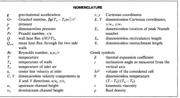
Grid refinement tests have been performed for the casewithRe= 114,Gr= lOOOandy= 180”.InFig.5 the distributions of heat transfer rate (Q = l%/a Ylw.,,) across the two side walls are shown. There is no sig- nificant difference among the results for the three meshes used. In the following the predictions using
150 x 120 grid are presented.
Effects of Grashof number
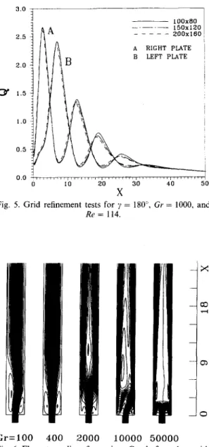
The streamlines for Gr = 100,400,2000.10 000 and 50 000 with Re = 114 and y = 0” are illustrated in Fig. 6. At the lowest Grashof number Gr = 100, an
asymmetric flow field is detected, with two different sizes of recirculating flow behind the steps. This kind of flow pattern is similar to that seen in Durst et
___ 100x80 --- 150x120 200x160 A RIGHT PLATE B LEFT PLATE 1.0 0.5 0.0 0 10 20 30 40 50 X
Fig. 5. Grid refinement tests for y = 180”, Gr = 1000, and
Re = 114.
Gr=lOO 400 2000 10000 50000
Fig. 6. Flow streamlines for various Grashof numbers with y=O”andRe=114.
a/. [ 151 and Tsui and Wang [17], in which forced convection (Gr = 0) was considered. The cause of the asymmetry is due to the instability of the shear layers separating the main stream and the two recirculation flows behind the two steps. There exists a point of inflection in the velocity profile, which is a necessary condition for instability according to the Rayleigh’s inviscid theory [22]. Small disturbances embedded in a shear layer may be amplified to form vortex-like structure, as observed by Sato [23] and Browand [24] in a boundary layer flow separating from a step. Due to confinement of the duct the two shear flows in the present case affect each other. The interaction of the two layers results in alternating shedding of vortices and, thus, flow asymmetry [ 161. In numerical cal- culations a source to cause asymmetric perturbation is the roundoff error and another is due to the relaxation
J J J J 2 -
r
Fig. 7. Three possible solutions for Gr = 0, y = 0” and
Re = 114.
scheme. In Fig. 7 three calculated results are presented for the case of forced convection. These solutions are obtained using SLR (successive line relaxation) which adopts the TDMA (tridiagonal matrix algorithm) as the relaxation scheme. On each grid line the TDMA behaves as a direct solver. In the first a vertical SLR (directed from inlet to exit) is incorporated to sweep from the left plate to the right plate, resulting in a larger recirculating eddy behind the left step. In the second the computational domain is swept by the vertical SLR from the right to the left. A seen in the figure, the two solutions are identical except that the flow patterns are reversed. When a horizontal SLR is used, the symmetrc solution is obtained because this relaxation scheme behaves as a symmetric solver. The above results demonstrate that with an asymmetric solver the solution would not be symmetric and the solution pattern may depend on the sweeping direc- tion. It should be noted that under severe conditions, such as in the buoyancy-opposed flow with large Grashof numbers, asymmetric solutions are always detected. This implies that flow instability can be trig- gered by such a small disturbance of roundoff error.
As seen in Fig. 6, the buoyancy force helps limit the growth of the instability where the Grashof number is low. At Gr = 400 the two recirculation regions are of the same size, being larger than the small recir- culation and smaller than the larger one of the
Gr = 100 flow. As Gr is further increased, the reat-
tachment length decreases and approaches zero. For
Gr > 2000 the recirculations are restricted to the back-
ward-facing steps, which has been observed by Lin et
al. [6] and Baek et al. [7]. Since the flows near the
walls are largely accelerated by the increased buoy-
--x -a3 .-I --a -0 Gr=lOO 400 2000 10000 50000
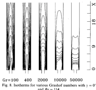
Fig. 8. Isotherms for various Grashof numbers with y = 0” and Re = 114.
ancy force, a reversed flow is formed in the centerline region downstream of the double step because mass flux must be conserved at each axial location. As a consequence, inflection points appears in the velocity profile at the edges of the recirculating flow. This triggers instability again and causes the flow to deviate from symmetry. However, as the Grashof number becomes very high (Gr = SOOOO), symmetric pattern returns. The central region becomes nearly stagnant, as will be apparent in viewing velocity profiles given latter, and a pair of recirculation zones are located between the stagnation central region and the wall flows.
In Fig. 8 isotherms are presented. Apparently, the contour patterns are closely related to the flow struc- ture represented by the streamlines. The axial velocity profiles at X = SW, are given in Fig. 9. As expected, the profiles for Gr = 100 and 10 000 are not symmetric while those for Gr = 2000 and 40000 exhibit good
1.0 0.6 0.6 U 0.4 0.2 0.0 -0.2-l,,,,,,, ! I, I, I I, I I I I, ! I, I / ( , / , -1.5 -0.5 0.5 1.5 Y
2692 Y.-Y. TSUI and S.-J. SHU (+868Q Cr=lOO oe+ma Gr=2000 -Gr=lOOOO M Gr=40000
X
Fig. 10. Heat transferred through the walls with y = 0” and
Re = 114.
Gr=lOO 800 2000
symmetric behavior. It is interesting to notice that for
Gr = 40 000 the flow in the center region between the
two reversed flows is nearly stagnant.
Fig. 11. Flow streamlines for various Grashof numbers with y = 0” and Re = 56.
The axial variation of the heat flux (Q = 133/a Yl,,,,) averaged over the two side walls is presented in Fig. 10. The heat flux increases with Gr in the initial stage near the inlet and decreases more quickly for the high
Gr cases. It is noted that the areas under the curves represent total heat transfers into the duct. The total heat added in must be the same, irrespective of Grashof number, if the fully developed state (i.e. 8 = 1) is reached at the outlet. From this point of view it is not surprising that the heat transfer rate is low in the late stage if it is high near the inlet. The location of the peak Q for the low Grashof number (Gr = 100) roughly correspond to the reattachment point of the smaller recirculation zone because the flow emerging from the inlet behaves like a jet and impinges on the wall around that location. According to the streamline plots shown in Fig. 6, when the Grashof number increases, the reattachment point moves upstream and finally the recirculation is limited to the step for Gr
larger than 2000. This results in that a part of the jet flow turns its direction to sweep across the step corners. Due to the combined effects of the jet-like flow and the turning flow in the Gr = 2000 and 10 000 cases the heat transfer rate, being high at the corners, declines first, followed by a rise, and finally decreases to the fully developed stage. For Gr = 40000 the entire flow turns immediately at the entrance, resulting in monotonic attenuation of the heat transfer.
-x
-co 3-I
-a
-0 .
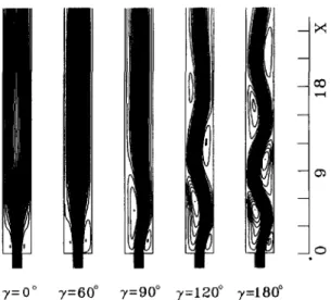
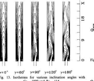
y=o” y=60” y=90” y=lZO” 73=180”
Fig. 12. Flow streamlines for various inclination angles with Gr = 1000 and Re = 114.
reversal takes place in the center region. However, different from the high Re flows, a pair of equal- strength recirculations are always detected at the cent- erline, as seen at Gr = 2000 and 10000.
Effects of orientation
As the Reynolds number reduces to 56, the rela- Streamlines for Re = 114 and Gr = 1000 at various tively large viscosity restricts the growth of instability inclination angles are sketched in Fig. 12. As indicated and, thus, the flow exhibits symmetric patterns, as previously, the buoyancy force assists to stabilize the evidenced in the studies of Durst et al. [15] and Tsui flow at this Grashof number and render the flow sym- and Wang [17]. The heat added does not change the metric at y = 0”. When the duct system is inclined to situation, as can be seen in Fig. 11. At low Grashof the vertical position, the buoyancy forces exerted on number (Gr = loo), the two recalculation zones are both sides of the duct are not of the same magnitude. of the same size. Similar to the case with Re = 114, However, the symmetry is maintained for small ys when the Grashof number becomes sufficiently large, despite the asymmetric buoyancy force distribution the two recirculations are limited to the steps and flow because this force is relatively small, comparing with
--x
-co .-I
-0l
-0
y=o” 7=6O” y=QO” 7=120’= 7=180°
Fig. 13. Isotherms for various inclination angles with Gr = 1000 and Re = 114.
the inertia force (&/Re* = 0.077). It is seen that the flow pattern only slightly deviates from symmetry at y = 60”. By positioning the duct horizontally (y = 907, the flow structure becomes fully asym- metric, with a small recirculation on the bottom wall (the right plate in Fig. 1) and a large one on the top. When the inclination angle is further increased, the component of the buoyancy force in the x direction opposes the flow direction. In this opposing flow, the flow is prone to Imstability. As a result, new recir- culation zones appear. As seen in the figure, on each side wall there exits two recirculations at y = 120”. By 180” the buoyancy force is directly opposite to the flow direction and the number of recirculations is increased to three. The isotherms are portrayed in Fig. 13. Obviously, the contours are shaped by the flow streamlines.
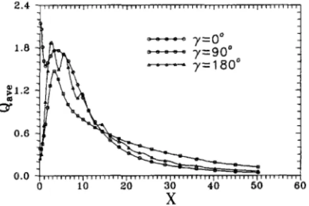
The heat transfers through the two walls for y = 0 and 90” are given in Fig. 14. At y = 0” the symmetric flow leads to collapse of the two curves into one while different curves are visible for y = 90”. The much larger peak value seen on the right plate in the latter is caused by the impingement of the jet-like flow on
cY
1.2 0.6 0.4 0.0 d 0 10 20 30 40 50 80 XFig. 14. Heat transferred through the walls for y = 0” and 90” with Gr = 1000 and Re = 114. 1.5 1.2 50.9 m 0.6 0.3
Fig. 15. Comparison of mean heat transferred along the walls for Gr = 1000 and Re = 114.
the wall. The results for y = 180” can be seen in Fig. 5. The oscillation reflects the wavy flow seen in Fig. 12. The peaks correspond to the positions where the main stream sweeps across the walls and the troughs are related to the recirculation centers. The peak values quickly decay with the axis. Comparison of the heat transfers averaged over the two plates for the three cases is made in Fig. 15. As mentioned above, the areas under the curves stand for the total heats added in and the total heat transfers must be equal provided that the temperature profiles at the exit of the duct are the same. Based on this understanding, the low level of heat transfer near the outlet for y = 0” simply reflects that it is superior to the other orien- tations. It is interesting to observe that the wavy flow helps to enhance heat transfer for y = 180”, making it more effective than the y = 90” case and comparable with that of y = 0”.
It was just observed that when the Grashof number is greater than 2000 in the aiding flow, flow reversal is formed in the centerline region and asymmetric structure appears. This can be seen from Fig. 16 in which the streamlines for Gr = 3000 are shown. By
--x
_a .-I -0) -0 y=O” 7=6O” 7=90” 7=120” 7=180” Fig. 16. Flow streamlines for various inclination angles with2694 Y.-Y. TSUI and S.-J. SHU 1.6 $1.2 0= 0.6 0.0 - y=oO - y=90° - y=180" 0 10 20 30 40 50
mrl
60 XFig. 17. Comparison of mean heat transfers along the walls for Gr = 3000 and Re = 114.
rotating the duct, the reversal gradually diminishes and completely disappears at y = 60”. It is interesting to notice from Figs. 12 and 16 that the inclination angle 60” seems to be a critical value. At this angle symmetric flow patterns prevail. However, this critical angle may depend on Reynolds number. In the hori- zontal direction, just like the low Re case, a large and a small recirculating flows appear behind the steps. Further increase in inclination angle results in a wavy flow with a number of recirculations residing on the side walls. The number of recirculations increases with the Grashof number and inclination angle. At y = 180”, there are four recirculations on the left wall and five on the right (being truncated in Fig. 16). For the opposing flow it is difficult to obtain converged solution for Grashof number greater than 3000 whereas, for the aiding flow, steady-state solution is possible for Gr up to 60 000. It implies that the oppos- ing flow is more sensitive to the flow instability and is prone to become unsteady [8, 91. The average heat fluxes across the walls shown in Fig. 17 demonstrate that the wavy structure of the opposing flow brings about more effective heat transfer than the horizontal duct does. However, the aiding flow is still the most preferred.
In the above the results are presented for 0” < y < 180”. Since the duct geometry and the imposed boundary conditions are symmetric to the centerline, the flow for an inclination angle y in the range between 180” and 360” is simply given by the flow for an angle of 360” -7, in which the roles of the right and left walls are interchanged. It is easy to see that when the angle y is replaced by 360”-y, the buoyancy force in the x direction (Gr cos y) is
unchanged and that in the y direction (Gr sin y) becomes negative. Owing to the symmetric con- figuration, it does not matter if the y component is negative or not. It is also interesting to note that the above results are applicable to both heating as well as cooling flows. In view of the following identities,
Grcosy = -G~cos(l8O”+y)
Grsiny = -Grsin(lSO”+y)
(7a) (7b)
a heating flow with a positive Gr at an inclination angle y is equivalent to a cooling flow with a negative
Gr at an inclination angle 180” + y.
CONCLUSIONS
A mathematical method has been developed to investigate the mixed convection flow through a double-step sudden expansion and into a duct with a uniform temperature imposed on the walls. Based on the calculated results, the following conclusion can be drawn.
(1) For buoyancy-assisted flow heat transfer helps
(2)
accelerate the flow near the heated wall and flow reversal takes place in the centerline region as the Grashof number becomes high enough. When the duct is placed vertically, the flow field remains to be symmetric throughout the Grashof number range tested for Re = 56. A pair of recirculating flows appear near the centerline as Gr becomes sufficiently large. At Re = 114 the asymmetric flow seen in the forced convection is first trans- formed to become symmetric at low Grashof numbers. It is followed by appearance of a single reversed flow in the centerline region and asym- metric pattern prevails again. By further increas- ing Grashof number the flow returns to become symmetric, with a pair of recirculations being adjacent to the high-speed near-wall flows. In the centerline region between the two recirculations the flow is nearly stagnant.
When the duct is inclined to the vertical position, a symmetric pattern is obtained at y = 60”. How- ever this critical angle may depend upon Reynolds number. In the horizontal position (y = 90”) different sizes of recirculation appear behind each side of the expansion. For y > 90” the opposing buoyancy force give rise to a number of recir- culations on the two side walls, and the main stream exhibits a wavy structure. The heat trans- fer peaks at the locations where the wavy flow attaches to the walls and is low in recirculation regions. The overall heat transfer is enhanced by the wavy flow, compared with the horizontally placed duct.
(3) Due to the symmetric arrangement the present results for heating flow are also applicable to coo- ling flow.
Acknowledgement-The authors wish to acknowledge the
support of the National Center for High-Performance Com- puting for providing computer resources.
REFERENCES
1. Lawrence, W. T. and Chato, J. C., Heat transfer effects on the developing laminar flow inside vertical tubes.
ASME Journal of Heat Transfer, 1966,88,214-222. 2. Aung, W. and Worku, G., Developing flow and flow
3. 4. 5. 6. 7. 8. 9. 10. 11. 12.
peratures. ASME’ Journal of Heat Transfer, 1986, 108, 299-304.
and inclined channel. International Journal of Heat and Habchi, S. and Acharya, S., Laminar mixed convection
in a symmetrically or asymmetrically heated vertical channel. Numerical Heat Transfer, 1986, 9, 6055618. Ingham, 0. B., Keen, D. J. and Heggs, P. J., Two- dimensional combined convection in vertical parallel plate ducts, including situations of flow reversal. Znter- national Journal of Numerical Methods in Engineering, 1988, 26, 1645-1664.
Sparrow, E. M. and Chuck, W., PC solutions for heat transfer and fluid downstream of an abrupt, asymmetric enlargement in a channel. Numerical Heat Transfer,
1987,12,1940.
Lin, J. T., Armaly, B. F. and Chen, T. S., Mixed con- vection in buoyancy-assisting, vertical backward-facing step flows. International Journalof Heat and Mass Trans- fer, 1990, 33,2121-2131.
Baek, B. J., Armaly, B. F. and Chen, T. S., Measure- ments in buoyancy-assisting separated flow behind a ver- tical backward-facing step. ASME Journal of Heat Transfer, 1993, 115,403408.
Chang, T. S. and Lin, T. F., Steady and oscillatory opposing mixed convection in a symmetrically heated vertical channel with a low-Prandtl number fluid. Znter-
national Journal of Heat and Mass Transfer, 1993, 36, 3783-3795. 13. 14. 15. 16. 17. 18.
Lin, T. F., Chang T. S. and Chen, Y. F., Development of oscillatory asymmetric recirculating flow in transient laminar opposing mixed convection in a symmetrically heated vertical channel. ASME Journal of Heat Transfer, 1993, 342, 3422352.
Lavine, A. S., Kim, M. Y. and Shores, C. N., Flow reversal in opposing mixed convection flow in inclined pipes. ASME Journal of Heat Transfer, 1989, 111, 114 120.
Bohne, D. and 0 bermeier, E., Combined free and forced convection in a vlertical and inclined cylindrical annulus.
Proceedings of the 8th International Heat Transfer Con- ference, ed. C. L.. Tien, V. P. Carey and J. K. Ferrel,
1986, 3, 1401-1406.
19.
20.
”
Mass Transfer, 1987, 30, 1307-I 3 18.
Lin. J. T.. Armalv. B. F. and Chen. T. S.. Mixed con- vecfion heat transfer in inclined backward-facing step flows. International Journal of Heat and Mass Transfer, 1991,34, 1568-1571.
Hong, B., Armaly, B. F. and Chen, T. S., Laminar mixed convection in a duct with a backward-facing step: the effects of inclination angle and Prandtl number. Znter- national Journal of Heat and Mass Transfer, 1993, 36,
3059-3067.
Durst, F., Melling, A. and Whitelaw, J. H., Low Rey- nolds number flow over a plane symmetric sudden expansion. Journal of Fluid Mechanics, 1974, 64, 11 l- 128.
Cherdron, W., Durst, F. and Whitelaw, J. H., Asym- metric flows and instabilities in symmetric ducts with sudden expansions. Journal of Fluid Mechanics, 1978,
84,13-31.
Tsui, Y. Y. and Wang, C. K., Calculation of laminar separated flow in symmetric two-dimensional diffusers.
ASME Journal of Fluids Engineering, 1995, 117, 612- 616.
Tsui, Y. Y., A study of Upstream-weighted high-order differencing for approximation to flow convection. Znter- national Journal for Numerical Methods in Fluids. 1991.
13, 167-199. ”
Rhie, C. M. and Chow, W. L., Numerical study of the turbulent flow past an airfoil with trailing edge sep- aration. AZAA Journal, 1983, 21(11), 1525-1532. Tsui, Y. Y. and Lin, J. Y., Flow calculation using non- staggered grids. Proceedings of the 8th National Con-
ference of the CSME, 1991,1,29-36.
-I,
LI.
22. 23.
Shu, S. J., Mixed-convection calculation in a two-dimen- sional duct preceded by symmetric diffusers. MSc. thesis, National Chiao Tung University, 1995. White, F. M., Viscous Fluid Flow, Chap. 5. McGraw- Hill, New York, 199 1.
Sato, H., Experimental investigation on the transition of laminar separated flow. Journal of the Physical Society
of Japan, 1956, 11.
24. Browand, F. K., An experimental investigation of the Maughan, J. R. and Incropera, F. P., Experiments on instability of an incompressible, separated shear layer. mixed convection heat transfer for airflow in a horizontal Journal of Fluid Mechanics, 1966, 26, 281-307.