Adaptive Transmission Control for Error-Resilient
Multimedia Synchronization
Chia-Chen Kuo, Guo-Shiang Ma, Ming-Syan Chen, Fellow, IEEE, and Jeng-Chun Chen
Abstract ———— Multimedia streams impose tight temporal constraints since different kinds of continuous multimedia streams have to be played synchronously. We devise in this paper an adaptive transmission scheme to ensure the error-resilient and synchronous playback of audio and video streams based on the Real-time Transport Protocol. Realization of our adaptive transmission control is composed of a series of operations in three stages, namely, (1) dynamic reordering mechanism, (2) error-resilient mechanism, and (3) adaptive synchronization mechanism. In this paper, an empirical study is conducted to provide insights into our adaptive transmission scheme. As validated by our performance study, the adaptive transmission mechanism is able to strike a good balance of both stable playback and the end-to-end delay reduction. Furthermore, we analyze the jitter resistance, the end-to-end delay, and video quality in order to enhance the applicability of this scheme to more applications that require the transmission of multimedia data.
Index Terms — Multimedia synchronization, error-resilient, jitter resistance
I. INTRODUCTION
Multimedia transmission requires the integration of different types of media streams. A temporal relationship exists among the information of these distinct streams. Multimedia systems must maintain the mutual relationship for proper data transmission and presentation. The process of maintaining the temporal relationship of one or several media streams is referred to as multimedia synchronization [6], [7]. Advances in communication technology lead to new applications in the areas of multimedia networking. Increased bandwidth of the network has made it feasible to provide various multimedia services, including video on demand, video conferencing, and distance learning, to name a few. These applications typically integrate different types of media objects, and the end clients of these services receive multimedia streams through the network for playback. Due to unreliable characteristics of the packet-switched network, the implementation of synchronization mechanism is deemed challenging [3], [9].
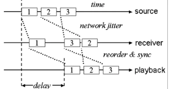
Fig. 1 illustrates the possibility of network jitters and packet out-of-orders lead to the network delay. Although the source sends out packets periodically, the incoming packets arrive at unpredictable time slots. Through the buffering mechanism of the receiver, it is possible to
achieve a reordered and synchronous playback by properly assigning the presentation time. However, the trade-off is the increased end-to-end delay and the buffer size required. How to minimize the delay is an important issue in multimedia synchronization. There have been various synchronization techniques proposed [5], [8], [12], [16]. Although prior works have employed adaptive schemes, most of them concentrated on single media continuity and did not deal with incoming Real-time Transport Protocol (RTP) [13] or error-resilient issues. To remedy this, we develop in this paper an adaptive transmission scheme based on RTP that is not only able to resist the inter-arrival jitters and the skew between audio and video streams but also able to minimize the end-to-end delay adaptively. In addition, our scheme consists of dynamic reordering and error-resilient mechanism which are both essential in improving the Quality of Service (QoS) of the multimedia transmission [10].
Fig. 1. The possibilities of end-to-end delay resulted from network jitters and packet out-of-orders
Realization of our adaptive scheme is composed of a series of operations in three stages, namely, (1) dynamic reordering mechanism, (2) error-resilient mechanism, and (3) adaptive synchronization mechanism. The first stage reorders the packets and sends them to the second stage upon its completion. It is so designed that only out-of-order packets incur extra processing delay. The second stage decodes the payload data which is then pushed to the third stage. In the meanwhile, a proper error-resilient algorithm is selected according to the network status to recover the possibly lost packets. The encoder can encode input video sequences according to variable channel error situations when a separate backward channel is available for the decoder to send packet loss reports. The most attractive feature is that error propagation can be completely removed soon at the decoder even without succeeding full INTRA-coded frames. When sufficient memory resources are
available at the encoder, it can encode frames using some previous correctly decoded frames for reference, thus removing error propagation at the decoder.
In the third stage, the adaptive synchronization mechanism is realized by adjusting the queuing length adaptively. This is the very significant part to achieve adaptive synchronization in our transmission scheme. The queue accumulates a certain amount of data before playback in order to resist inter-arrival jitters and variances of the end-to-end transmission delay. In addition, by comparing timestamp fields of audio and video streams, we can identify the matching audio and video slices for synchronous playback. Another important benefit of this mechanism is that no matter how much processing delay does the reordering and error-resilient algorithms of previous stages spend, our adaptive synchronization algorithm is able to control the queuing length precisely to eliminate the time-based skew between the audio and video streams and minimize the end-to-end delay. This design makes it feasible to improve the reordering and error-resilient algorithms independently or even change the decoding codecs or error-resilient methods dynamically without affecting the audio and video synchronization afterward.
This paper is organized as follows. The system model and involved standards are described in Section II. The adaptive transmission scheme for error-resilient multimedia synchronization is developed in Section III. In addition, the performance study is presented in Section IV. Finally, this paper concludes with Section V.
II. PRELIMINARY
To validate our adaptive transmission control for error-resilient multimedia synchronization, we develop an ITU-T H.323 [2] compliant videoconferencing application with a focus on highly interactive conferences. In order to improve the error resiliency, this software application takes advantage of two-way communication mechanisms such as acknowledgments of correctly received packets via backward channel messages. Considering the clarity of performance evaluation, we introduce error concealment techniques for video communications to elucidate our transmission scheme. Our adaptive transmission scheme can be utilized on other error concealment techniques [4], [11] for audio and video communications. Since each error concealment algorithm has its advantages and disadvantages with regard to the time complexity, the buffer size, and the recovery quality, we can dynamically switch to the suitable algorithm depending on packet loss fraction reported from RTCP [14]. While the network status is good enough, the error concealment is not required and the resources consumption, such as the CPU power, the
memory space, and the processing delay can thus be reduced.
A. Error-Resilient Video Communication
Packet losses can severely degrade the quality of future decoded pictures at the decoder since an IP packet usually carries an integer number of macroblock (MB) rows. Obviously it is not sufficient to just apply post-processing techniques for error concealment. The ITU Recommendation H.245 [1] allows the encoder and decoder to build an out-of-band channel on which the decoder can return packet loss information. To exploit this feature, our design makes good use of a connection-oriented data channel. Upon backward channel messages sent from the decoder, the encoder can take into account the packet loss and encode either severely damaged MBs in INTRA mode or less affected MBs in INTER mode.
Fig. 2. Transmission model of error-resilient video communication
As shown in Fig. 2, the out-of-band channel is used as a separate backward channel for adaptive error concealment. Since it is built upon TCP sockets, all backward messages can reach the encoder in order and remain intact. The session management is responsible for passing these messages to its forward video channel. Then the encoder processes all received back-channel messages before a new input video frame is to be encoded. This technique has two operation modes, i.e., NACK and ACK modes. As will be seen later, the NACK mode is preferred when packet loss rate is low since it places little burden on the output bandwidth. The ACK mode works better at high packet loss rates since a single packet loss only affects one frame.
B. Real-time Transport Protocol
Real-time Transport Protocol (RTP) [13] has been designed within the Internet Engineering Task Force (IETF). The data part of RTP is a thin protocol providing the support for applications with real-time properties, including timing reconstruction, loss detection, security, and content identification. RTP header contains the following information.
Payload type: A one-byte payload type identifies the
kind of payload contained in the packet, e.g., H.263 video or G.723 audio.
Timestamp: A 32-bit timestamp describes the
generation instant of the data contained in the packet. The frequency clock of timestamp depends on the payload type. We can slice one video frame into several packets with the same timestamp and order them by consecutive sequence numbers.
Sequence number: A 16-bit packet sequence number
allows loss detection and reordering within a series of packets with the step-up sequence numbers.
Other fields are not described here in the interest of brevity. Depending on these fields, RTP provides delivery services for information with real-time characteristics, such as interactive audio and video communication. As we know, UDP, the well-handled transport protocol on IP-based network, does not ensure the orderly transmission of packets. Due to unreliable characteristics of the packet-switched network, the packet loss, data out-of-order and inter-arrival jitters may occur [6]-[8], [16]. RTP provides scores of useful information for the synchronization among media streams of different types. The incremental sequence number is used for reordering and the judgment of packet loss. By comparing the differences of timestamps between media objects, we decide the playback instants with clock precision for the purpose of synchronization. In addition, we are capable of compensating lost packets by audio and video error-resilient algorithms in order to improve the QoS.
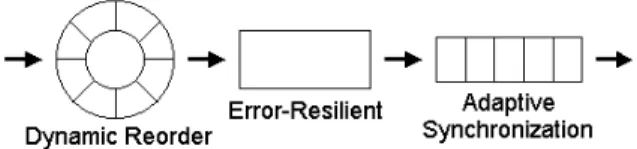
Fig. 3. Three stages of proposed adaptive transmission control
III. ADAPTIVE TRANSMISSION CONTROL
The adaptive transmission scheme we developed consists of three stages, namely, (1) dynamic reordering mechanism, (2) error-resilient mechanism, and (3) adaptive synchronization mechanism. As shown in Fig. 3, the first stage reorders packets received from the network and sends them to the second stage. After decoding and recovering the payload data, media objects are pushed into the third stage and played synchronously according to our adaptive algorithm. The details of these three stages are described in the following subsections.
A. Dynamic Reordering Mechanism
Dynamic reordering mechanism invokes a certain amount of buffer which accumulates packets before forwarding them to the next stage. At the same time, it
reorders the packets according to the sequence number field in order to reduce the occurrences of packet out-of-order to a certain degree depending on the buffer size. In addition, if the packet which should arrive on time is not received before the time it is supposed to be passed to the next stage, we treat such a situation as a packet loss no matter it encounters a real loss or just a short-run delay. Note that such kind of packets can be recovered in the next stage.
In order to put each incoming packet with a sequence number, we apply a circular data structure on the reordering buffer. Assuming that our system provides the buffer size N, we take the sequence number n of incoming packets and divide by N to get the remainder n mod N in order to decide the position for each packet. The procedure of dynamic reordering, abbreviated as DR, is described below.
Procedure DR: procedure of dynamic reordering Step 1: Initialize all slots of the reordering buffer. Step 2: Assuming that the sequence number of the first
packet is m, we set an expected sequence number E as
m+1 and immediately send to the next stage a repackaged
packet with the necessary information, including the sequence number, the timestamp, the payload type and the payload data. The expected number E is an indicator to decide the operation for each incoming packet by checking their sequence numbers.
Step 3: Wait for the next incoming packet. Once
receiving the new packet, check its sequence number n.
Step 3.1: If n is smaller than E, it implies that the packet
is obsolete. Skip this packet and return to Step 3.
Step 3.2: If n equals to E, meaning that this packet is
what we expect, we check the slots from n mod N to
n+N-1 mod N of the reordering buffer sequentially until we
encounter an empty slot. If slot k mod N (n≤k≤n+N−1) is not empty, pop out the repackaged packet to the next stage and set E as k+1. Otherwise stop the checking process and then return to Step 3. This step will flush out all continuous packets starting from n.
Step 3.3: If n falls between E and E+N, it implies that
the packet we expect has not arrived yet. We shall wait for the expected packet to reorder incoming packets. Thus, we store the necessary information of the incoming packet in slot n mod N and then return to Step 3.
Step 3.4: If n is equal to or larger than E+N, it implies
that the packet we expect has not arrived yet. However, in this case we cannot wait any longer because of the buffer overflow. Hence, we treat these packets with sequence number from E to n-N as lost packet and clear correlative slots. In addition, we store the necessary information of this incoming packet in slot n mod N. Finally, check the slots from n-N+1 mod N to n mod N of the reordering buffer sequentially until we encounter an empty slot. If slot k mod
packet to the next stage and set E as k+1. Otherwise stop the checking process and return to Step 3.
By procedure DR, the buffer accumulates dynamically only if incoming packets encounter the situation of packet out-of-order or packet loss. If incoming packets are received sequentially, we can pass them to the next stage in time without any extra processing delay. Note that the buffer size N affects the worse case of end-to-end delay. It is unnecessary to set N too high to overspend the memory space.
B. Error-Resilient Mechanism
While no packet loss is present during video transmission, the encoder can always successfully encode data with the expected coding efficiency. However, when the encoder does not know that some packets did not reach the other end; subsequent decoded frames will suffer from degradation in visual quality due to predictive coding. With NACK or ACK messages from the decoder, the encoder can react to them right away to eliminate error propagation at the decoder.
NACK Mode: operation of low packet loss rate
When operating in the NACK mode without any packet loss, the decoder keeps sending backward acknowledgment messages for the encoder to maintain frame buffers. By checking the TR (Temporal Reference) field in an ACK message, the encoder can then safely release frame buffers prior to the acknowledged frame. The best coding efficiency is maintained since the time lag between the reference frame and the current one is always one frame interval. After a packet loss, the decoder sends an NACK with the RTR (Requested Temporal Reference) field set to the temporal reference of some previous correctly decoded frame kept at the decoder. Upon the receipt of this NACK message, the encoder then encodes data using the decoder's requested frame for reference. The TRP (Temporal Reference for Prediction) field in our modified RFC 2032 [15] header is set to the RTR value in this NACK message to inform the decoder which backup frame is used for reference.
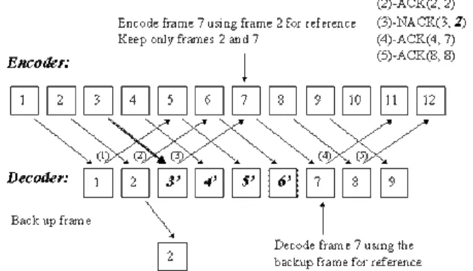
When a transmission error occurs, the decoder sends through the backward channel a negative acknowledgment message to inform the encoder. Consider the execution scenario in Fig. 4 as an example. In Fig. 4, assume that frame 3 cannot be correctly decoded. The decoder then backs up frame 2 into its additional frame buffer and sends backward NACK(3, 2) requesting the encoder to use frame 2 for reference. On receipt of an NACK for frame 3 before the encoding of frame 7, the encoder can therefore use frame 2 for reference and free the memory resources for frame 3 through frame 6 since these frames are all corrupt at the decoder. Until the encoded data of frame 7 arrives, the decoder suffers from using inconsistent frames for
reference for the period of one round trip delay. It is worth mentioned that the decoder requires only one additional frame buffer in NACK operation mode. If the round trip delay is short, which is assumed to be one of the error characteristics of LANs, the impact of packet losses at the decoder can be removed after an acceptable period of time. The advantage of this mechanism over simple INTRA updates lies in the increased coding efficiency.
Fig. 4. Illustration of operation in the NACK mode
ACK Mode: operation of high packet loss rate
When operated in the ACK mode, the decoder sends ACK messages to acknowledge all correctly decoded frames and the encoder uses for reference only the requested frame indicated in the back-channel message. The coding performance is lower even when no transmission errors occur since the time lag between the reference frame and the current frame is more than one round trip delay. However, error propagation can be avoided entirely since only acknowledged frames are used for reference.
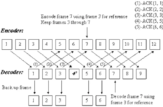
Consider the execution scenario in Fig. 5 as an example. The decoder acknowledges and backs up every correctly decoded frame until an error occurs to frame 4. Since frame 5 is encoded using frame 1 for reference, the decoder can still correctly decode frame 5 in reference to its backup frame 1 without any error propagated from corrupt frame 4. It is worth mentioned that no succeeding frames would be in reference to frame 4. The decoder can thus avoid error propagation after the error to frame 4 entirely. When the decoder receives data for frame 6, it can safely free the frame buffer for frame 1 and use frame 2 for reference. To reduce the number of additional frame buffer at the decoder by half, every two ACK messages could request the same previous reference frame. It is noted that sufficient previous frames at the encoder are required to cover the maximum round trip delay of NACK and ACK messages. However, the number of additional frame buffers at the decoder can be reduced to one in the NACK mode. Storage reduction by half is possible in the ACK mode at the cost of slightly increased bit rates.
Fig. 5. Illustration of operation in the ACK mode
C. Adaptive Synchronization Mechanism
The adaptive synchronization mechanism is realized by adjusting the queuing length adaptively. As mentioned earlier, this is the very significant part to achieve adaptive synchronization in our transmission scheme. The queue accumulates a certain amount of data before playback in order to resist inter-arrival jitters and variances of the end-to-end transmission delay. By comparing timestamp fields of audio and video streams, we can identify the matching audio and video slices for synchronous playback.
We define TS(An) and TS(Vm) as the timestamps of audio and video streams with the incoming orders being n and m, respectively. The unit of timestamp depends on the clock frequency of the payload type defined in RFC1890 [14]. Generally speaking, the audio is based on 8KHz and the video is based on 90KHz. From the first incoming data, we get the timestamp as original TS(A0) and TS(V0). Therefore, TS(An)-TS(A0) and TS(Vm)-TS(V0) divided by their clock frequency CF(A) or CF(V) of the media type represents the distance of actual playback time from the first packet. By comparing with the presentation time of the audio PT(An) = [TS(An)-TS(A0)]/CF(A) and that of the video PT(Vm) = [TS(Vm)-TS(V0)]/CF(V), we are able to determine the precise playback time of audio and video based on global timer in order to achieve synchronization. The procedure of global timer synchronization (abbreviated as GTS) is described below.
Procedure GTS: procedure of synchronization based on
the global timer
Step 1: We define the playback queuing lengths of audio
and video as QL(A) and QL(V), respectively, and wait for the queuing lengths to reach the values of QLAinit and
QLVinit. The system starts to check and pop out the queuing data until both QL(A0)
≥
QLAinit and QL(V0)≥
QLVinit.
Step 2: We set a global timer which checks the status of
audio and video buffers frequently with a polling period P which is selected to be shorter than the arrival interval of
packets. The shorter the P, the more precise the synchronization will be and the more system overhead will be incurred. The global timer GT, the presentation time of audio PT(A0), and the video PT(V0) are all set to zeros initially.
Step 3: Wait for the polling instant with period P, and
then check the presentation time PT(An) and PT(Vm) of packets in front of the queue. In addition. We keep the value of minimal queuing length of both audio and video as
QLAmin and QLVmim, respectively. If the current QL(A)
≤
QLAmin, we set QLAmin = QL(A) to update the minimal value. Similarly, if QL(V)≤
QLVmin, we set QLVmin =QL(V). If the audio or video queue is underflow with zero
queuing length, restart from Step 3. If the underflow occurs continuously, it implies that a severe problem occurs due to network lag or even disconnection. In such a condition, we reset the synchronization mechanism.
Step 3.1: If PT(An) or PT(Vm) is equal to or larger than
GT+P/2, it implies that it is not yet the time to play the
audio or video data. In this case, simply return to Step 3.
Step 3.2: If PT(An) or PT(Vm) falls between GT-P/2
and GT+P/2, it implies that it is the time to play the audio or video data. Pop out the audio or video data, send them to the playback device, and then return to Step 3.
Step 3.3: If PT(An) or PT(Vm) is equal to or smaller than GT-P/2, it implies that it is too late to play the audio or video data. Skip and flush audio or video data, and then check the next packet until the presentation time falls between GT-P/2 and GT+P/2 or the buffer underflow. Return to Step 3.
Because both audio and video streams are based on identical global timer GT, it is ensured that the audio and video will be synchronously played out by procedure GTS. In addition, by considering the arrival skew between audio and video and variances of the end-to-end delay, we control the queuing length and playback speed in order to increase the stability of playback and minimize the end-to-end delay. In every polling instant, we get the values of queuing lengths QL(A) and QL(V). It can be seen that the value of queuing length will vary in a certain range because of unpredictable inter-arrival jitters and network delays, and the threshold of queuing length dominates the end-to-end delay and jitter resistance. Our goal is to minimize the average queuing length while maintaining media synchronization and stable playback. Thus we can minimize the end-to-end delay depending on the network status. The concept is depicted in Fig. 6.
Fig. 6. Concept of adaptive synchronization mechanism
According to the global timer, we check the status of minimal queuing lengths QLAmin and QLVmin frequently with certain periods. These periods of adaptive modifications should be longer than the polling period P for good stability. The procedure of adaptive synchronization to minimize the end-to-end delay (abbreviated as ASMD) is described below.
Procedure ASMD: procedure of adaptive
synchronization to minimize end-to-end delay
Step 1: If QLAmin
≥
2 and QLVmin≥
2, set GT = GT+Pin order to advance the playback instant and reduce the end-to-end delay.
Step 2: If QLAmin = 0 or QLVmin = 0 which stands for the buffer underflow, set GT = GT-P in order to postpone the playback instant to avoid buffer underflow.
Step 3: Reset QLAmin and QLVmin for next evaluation of the minimal queuing length.
Procedure ASMD keeps the shorter queuing length between audio and video to one and avoids possible oscillations which decrease the system stability.
IV. PERFORMANCE STUDY
To evaluate the performance of our adaptive transmission scheme, we conduct an empirical study to provide insights into our scheme. We developed a software module of packet generation which is capable of simulating various network conditions.
A. Evaluation of End-to-End Delay
In this system, we define the values of related parameters of RTP packets as follows.
Audio: CF(A) = 8000 and TS(An) = n*400 (20 samples/s)
Video: CF(V) = 90000 and TS(Vm) = m*6000 (15
frames/s)
Polling Period: P = 20 ms is selected, which is smaller
than the arrival interval of audio and video.
Evaluated packets are generated sequentially with a variable delay interval to simulate the network jitters and possible packet out-of-order conditions. We define the arrival time of packets as TS/CF+Jitter(x) seconds. Jitter(x) is a random time value within the range 0 Jitter(x) x.
Clearly, the expected average delay time is Jitter(x)/2. In addition, if x TS/CF, packets can be out of order.
As mentioned above, we implemented a module to realize the adaptive transmission scheme. This module consists of the first stage which invokes procedure DR and the third stage including procedures GTS and ASMD. The variance of arrival jitters will validate the adaptability of our transmission scheme. We set the buffer size of dynamic reordering buffer to 3 and set an initial value of queuing length for both QLAinit and QLVinit to 5. Because the arrival
frequency of audio (20 samples/s) is larger than video (15 frames/s), the queuing length of the audio is longer than that of the video on the average from the starting point.
The synchronization module accepts and analyzes the packets generated from the packet generation module. We set the checking period, every 10 seconds, to modify the global timer according to procedure ASMD. In the meantime, the system maintains the average queuing length as it proceeds. The results are shown below.
Fig. 7. Average queuing lengths are minimized as time advanced
Fig. 7 shows the trend of average queuing length according to different jitter variances. It is worth mentioned that the length is reduced to a stable value as time advances. A shorter queuing length corresponds to a shorter end-to-end delay. As shown in Fig. 8, larger jitters require more buffering spaces to avoid the buffer underflow. Depending on the network conditions, our transmission scheme is able to minimize the delay adaptively as well as to preserve a stable playback. As validated by our empirical results, the QoS is improved prominently and our adaptive transmission scheme is flexible to apply to comprehensive applications.
Fig. 8. The impact of jitter to queuing lengths
B. Evaluation of Video Quality
We select the H.261 codec to incorporate error-resilience mechanisms since it is more suitable for our frame-based experiment and also the bandwidth is not our main concern because our target network environment is local area networks. Our proposed mechanism is in fact applicable to different video coding standards as long as the RTP payload-specific header format and back-channel message format are available.
To simulate real-time video conferencing, our system encodes the first 800 frames of a standard videophone sequence (Mother and Daughter) in the QCIF format. This video sequence has little motion in it and the background scene does not change frequently as in a video-conferencing setting. We conducted two sets of experiments where one set is in the NACK mode and the other in the ACK mode. Each set has four different packet loss rates so as to observe the impact of packet loss. The same packet loss patterns are used in both sets for fair performance comparison.
The video channel of our H.323 videoconferencing application feeds the H.261 codec 15 input video frames every second. Each frame is first encoded and packetized into three packets on a GOB basis. A modified RFC 2032 [15] header is prefixed to each packetized data packet. The video channel then passes all packets to its RTP module for real-time transmission. Bit rates of 128 kbps are used to simulate high-bandwidth LAN connections. A constant quantizer of 8 is used for encoding the whole sequence. We compare the robustness to errors of an H.261 video coder with only error concealment to another H.261 coder that takes advantage of a feedback channel. The backward channel is error-free since it transports back-channel messages by TCP.
The average peak signal-to-noise ratio (PSNR) is used as a distortion measure of objective quality. Note that PSNR is of less interest when a feedback channel is available since some focus should be set to the relationship between the average bit rate and the time lag of error concealments. To illustrate the trade-offs among compression performance and video quality, we measure frame sizes and PSNR values. The forced updating in H.261 claims that a macroblock should be INTRA-coded at least once for every 132 times of its transmission. The H.261 codec simply
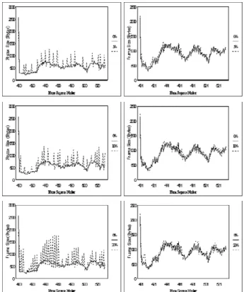
INTRA-codes one whole frame every 133 frames. Here we present the results for frame 400 through frame 532 in Fig. 9 and 10.
In Fig. 9, each of the frame size curves with different loss rates (5%, 10%, and 20%) is compared with that at zero packet loss rates. In the NACK mode, each frame error can result in a sudden frame size increase of some subsequent frame. As the packet loss rate rises above 10%, the variance of frame size can be quite dramatic. This can be a burden to a constant bit rate coder. Note that as the loss rate increases, the overall bit rate increases accordingly. It implies that the NACK mode is not a good option at high loss rates due to the increases in both bit rates and the number of corrupt frames at the decoder.
Fig. 9. Encoded frame size over frame sequence number of NACK (left) and ACK (right) modes with different packet loss rates
All curves of frame size look similar to one another in the ACK mode despite different loss rates. Since only acknowledged frames are used for prediction, packet loss has little impact on the average bit rate as long as the loss rate is not beyond 50% and the round trip delay for the backward channel is short. From Table 1, we can see that the average bit rate is in the range of 120-124 kbps. Unlike in the NACK mode, there is no obvious bit rate increase in the ACK mode as the loss rate rises. When the packet loss rate is below 5% in the NACK mode, the average frame size is slightly larger than 615 bytes and the average bit rate is below 80 kbps as shown in Table 1. In the ACK mode, however, the average frame size is 1014 bytes and the
average bit rate is 120 kbps even at zero loss rates. In other words, the ACK mode requires 50% more bandwidth than the NACK mode does even when no packet loss is present.
Fig. 10. Y-PSNR performance over frame sequence number of NACK (left) and ACK (right) modes with different packet loss rates
From Fig. 10 we can see that the NACK mode is more sensitive to packet loss in terms of PSNR values than the ACK mode. Note that PSNR values fluctuate due to the selection of reference frames. Without the capability of selecting reference frames, the curve would have gone down to a level that blocking artifacts and blurring could be very annoying. It is possible to improve the PSNR performance if sophisticated error concealment techniques are employed, which is orthogonal to the main theme of this paper. This issue, however, is orthogonal to the main
theme of this paper. Note that we do not stress the need of improving PSNR values since errors can be removed after about one trip delay time. When the frame rate is high and the round trip delay is short, the time period of affected frames can be tolerable. Again, the ACK mode has a better PSNR performance over the NACK mode since the adverse impact of a packet error is confined to a single frame.
The average PSNR values in Table 1 are measured on 665 frames (from frame 134 through frame 798) of the test sequence. We can see that the ACK mode is not sensitive to packet loss in terms of PSNR values. The ACK mode outperforms the NACK mode primarily because only acknowledged frames are used for reference. From Table 1 we can also see that the average bit rate for the ACK mode is quite high even without packet loss. Therefore, the system we devised starts with the NACK mode and switches to the ACK mode when a threshold is met. This threshold needs to take into account the bit rate, the packet loss rate, the number of additional memory buffers, and the number of affected frames at the decoder.
V. CONCLUSIONS
In this paper, we presented an adaptive transmission scheme to ensure the error-resilient and synchronous playback of multimedia streams based on the Real-time Transport Protocol. Furthermore, we analyzed the jitter resistance, the end-to-end delay, and video quality in order to make this scheme more applicable to comprehensive applications. We conducted an empirical study to provide insights into our scheme. As validated by our experimental results, the adaptive transmission control proposed is able to strike a good balance of both stable playback and the end-to-end delay reduction. In view of the increasing popularity of Internet applications, the results in this study are very timely and important for achieving better QoS in many multimedia and networking applications.
Loss Rate 0% 5% 10% 20%
NACK ACK NACK ACK NACK ACK NACK ACK Average video bit rate 73.3 120.8 78.7 121.6 81.7 122.8 87.3 124.0
Average Y-PSNR 34.965 35.084 34.712 35.009 34.325 34.921 33.498 34.53 No. of affected frames
Total Number=665 0 0 396 101 511 209 575 453
Ave. no. of frames
buffer at the encoder 5.41 5.55 4.29 5.79 3.95 6.26 3.61 6.12
REFERENCE
[1] ITU-T Recommendation, “H.245: control protocol for multimedia communication,” International Telecommunication Union, 1996. [2] ITU-T Recommendation, “H.323: Visual telephone systems and
equipment for local area networks which provide a non-guaranteed quality of service,” International Telecommunication Union, 1996. [3] J. Bolot, “End-to-end packet delay and loss behavior in the
Internet,” Proceedings of ACM SIGCOMM, pp. 289-298, 1993. [4] G. Carle and E. W. Biersack, “Survey of error recovery techniques
for IP-based audio-visual multicast applications,” IEEE Network, Vol. 11(6), pp. 24-36, 1997.
[5] J. Escobar, C. Patridge, and D. Deutsg “Flow synchronization protocol,” IEEE/ACM Transactions on Networking, Vol. 2, pp. 111-121, 1994.
[6] Y. Ishibashi and S. Tasaka, “A comparative survey of synchronization algorithms for continuous media in network environments,” Proceedings of IEEE Local Computer Networks, pp. 337-348, 2000.
[7] Y. Ishibashi, S. Tasaka and H. Ogawa, “A comparison of media synchronization quality among reactive control schemes,” Proceedings of IEEE INFOCOM, Vol. 1, pp. 77-84, 2001. [8] H. Kanakia, P. Mishra, and A. Reibmanm, “An adaptive congestion
control scheme for real-time packet video transport,” IEEE/ACM Transactions on Networking, Vol. 3(6), pp. 671-682, 1995. [9] D. Loguinov and H. Radha, “End-to-end Internet video traffic
dynamics: statistical study and analysis,” Proceedings of IEEE INFOCOM, 2002.
[10] D. Miras, “A survey on network QoS needs of advanced Internet applications,” Internet2 QoS Working Group, Working Document, 2002.
[11] C. Perkins, O. Hodson, and V. Hardman, “A survey of packet-loss recovery techniques for streaming audio,” IEEE Network, 12(5), pp. 40-48, September 1998.
[12] R. Ramjee, J. Kurose, and D. Towsley, “Adaptive playout mechanisms for packetized audio applications in wide area networks,” Proceedings of IEEE INFOCOM, pp. 680-688, 1994. [13] H. Schulzrinne, S. Casner, R. Frederick, and V. Jacobson, “RTP: a
transport protocol for real-time applications,” Internet Engineering Task Force, Audio Visual Working Group Request for Comment RFC 1889, 1996.
[14] H. Schulzrinne, S. Casner, R. Frederick, and V. Jacobson, “RTP profile for audio and video conferences with minimal control,” Internet Engineering Task Force, Audio Visual Working Group Request for Comment RFC 1890, 1996.
[15] T. Turletti and C. Huitema, “RTP payload format for H.261 video streams,” Internet Engineering Task Force, Audio Visual Working Group Request for Comment RFC 2032, 1996.
[16] M. Yuang, S. Liang, Y. Chen, and C. Shen, “Dynamic video playout smoothing method for multimedia applications,” Multimedia Tools and Applications 6, 1998.
Chia-Chen Kuo was born in Taichiung, Taiwan,
R.O.C., in 1976. He received the B.S. degree in Electrical Engineering from National Taiwan University, Taipei, in 1997. He is currently a Ph.D. candidate in the department of Electrical Engineering at National Taiwan University.
His research interests include video coding techniques, networked multimedia, and multimedia database system.
Guo-Shiang Ma received the B.S. degree in
Electrical Engineering from National Chung Cheng University in 1998 and the M.S. degree in Electrical Engineering from National Taiwan University in 2000. He is currently working as a software engineer at Ulead Systems in Taiwan.
His research interests include error concealment algorithm and networked multimedia.
Ming-Syan Chen received the B.S. degree in
electrical engineering from National Taiwan University, Taipei, Taiwan, and the M.S. and Ph.D. degrees in Computer, Information and Control Engineering from The University of Michigan, Ann Arbor, MI, USA, in 1985 and 1988, respectively. Dr. Chen is currently a professor and the chairman of Graduate Institute of Communication Engineering, a professor in EE Department, and also a professor in CSIE Department, National Taiwan University, Taipei, Taiwan. He was a research staff member at IBM Thomas J. Watson Research Center, Yorktown Heights, NY, USA from 1988 to 1996. His research interests include database systems, mobile computing systems, and multimedia networking, and he has published more than 170 papers in his research areas.
In addition to serving as program committee members in many conferences, Dr. Chen served as an associate editor of IEEE Transactions on Knowledge and Data Engineering (TKDE) from 1997 to 2001, is currently on the editorial board of Very Large Data Base (VLDB) Journal, Knowledge and Information Systems (KAIS) Journal, Journal of Information Science and Engineering (JISE), and Journal of the Chinese Institute of Electrical Engineering, and is a Distinguished Visitor of IEEE Computer Society for Asia-Pacific from 1998 to 2000. He served as program chairs/co-chairs and tutorial speakers in many conferences. He holds, or has applied for, eighteen U.S. patents and seven ROC patents in his research areas. He is a recipient of the NSC (National Science Council) Distinguished Research Award and K.-T. Li Research Penetration Award for his research work, and also the Outstanding Innovation Award from IBM Corporate for his contribution to a major database product. Dr. Chen is a Fellow of IEEE and a member of ACM.
Jeng-Chun Chen received her B.S. degree in
Electrical Engineering from National Taiwan University in 1985 and her M.S. degree in EECS from University of Michigan, Ann Arbor, Michigan, USA, in 1986. Later she joined Michigan Research Institute (MHRI) in Ann Arbor. In 1989, she joined IBM T. J. Watson Research Center in New York where she involved in computer architecture and multimedia research. In 1996, she joined Philips in Taipei and was in charge of the research programs of Information Appliance Systems in Philips Innovation Center Taipei.
She became the department head of Research Strategy and Regional Operations of Philips Research East Asia in 2001 and the director of Philips Research East Asia – Taipei in 2002. She is now the CTO of Arcadyan Technology Corporation, a joint venture between Philips and Accton on wireless technologies. Her current areas of focus include information appliances, networked multimedia, and wireless applications.