Mode locking of semiconductor lasers in a
coupled-cavity configuration with a
strongly coupled empty auxiliary cavity
Ching-Fuh Lin
Graduate Institute of Electro-Optical Engineering and Department of Electrical Engineering, National Taiwan University, Taipei, Taiwan
Received August 8, 1995; revised manuscript received June 18, 1996
Mode locking of semiconductor lasers in a coupled-cavity configuration with an empty auxiliary cavity is stud-ied theoretically. The empty auxiliary cavity, when strongly coupled to the main cavity, is found to influence the pulsation situation significantly. The predicted pulse widths and chirp parameters in the steady state are in good agreement with the experimental measurements. The influences of the linear phase shift induced by the cavity-length variation and the self-phase modulation in the main cavity on the pulsation are also briefly discussed. © 1997 Optical Society of America. [S0740-3224(97)02601-5]
A coupled-cavity configuration is an effective way of gen-erating ultrashort optical pulses.1,2 The schemes involv-ing coupled-cavity configurations have been termed coupled-cavity, additive-pulse, and interferential mode locking.3 The coupled-cavity configuration is used to augment the original laser cavity with an auxiliary cavity that contains a nonlinear optical element. An optical fi-ber is usually used as the nonlinear optical element to force the optical pulses to undergo significant self-phase modulation (SPM), which induces different phase shifts at the wings and the center of the pulses. As the length of the auxiliary cavity is adjusted to match that of the main cavity so that destructive interference occurs at the wings of the overlapped pulse, the pulse is shortened. The SPM in the auxiliary cavity is essential for the pulse-shortening effect. However, it should be reasonable to assert that the required SPM can be placed in the main cavity and also that an empty auxiliary cavity will assist pulse shortening. Although an additional nonlinear ele-ment is seldom used in the main cavity, because it will then raise the lasing threshold, the existing element in the main cavity might exhibit SPM. Therefore this paper will explore the pulse-shortening effect caused by an empty auxiliary cavity because the main cavity already has SPM.
Without the insertion of any additional nonlinear ele-ments in the main cavity, an empty auxiliary cavity has been reported to generate short optical pulses.4–6 The short pulses were generated only with the auxiliary mir-ror in motion, which in explanation was said to introduce a continuously changing phase shift in the feedback path.7 The induced frequency shifting then prevents the dominance of a single frequency and the operation of con-tinuous oscillation, resulting in a response that resembles mode locking. The empty auxiliary cavity4–6 offers one simple and effective way of generating ultrashort pulses. However, the mode locking is not sustained steadily, and so the auxiliary mirror needs to be driven to move
peri-odically. The mode locking builds up and decays accord-ingly. On the other hand, with the auxiliary mirror fixed at a given position, an empty auxiliary cavity has also been reported to significantly shorten the pulses gener-ated from an external-cavity semiconductor laser.8 In this experiment a significant amount of SPM is suspected to exist in the monolithically integrated absorber in the laser-diode chip and to play an important role in the pulse-shortening effect. With the SPM in the main cav-ity, this configuration behaves, as a matter of fact, more like the traditional coupled cavities with a nonlinear aux-iliary cavity than like those with a moving auxaux-iliary mir-ror. A quantitative study of mode locking in such a coupled-cavity configuration with an empty auxiliary cav-ity fixed at a given position is presented in this paper. With the existing SPM in the main cavity, this coupled-cavity mode-locking technique provides an even simpler way of generating ultrashort pulses than previous techniques4–6with a moving mirror.
A model starting from those that were previously used to explain additive-pulse mode locking with a nonlinear auxiliary cavity9–11is developed. Previous models10,11of additive-pulse mode locking approximate the coupling of the two pulses to yield a simple formulation for the coupled-cavity configuration because only weak feedback is returned to the main cavity. In this paper no approxi-mation is made for the coupling. A simple formulation is still obtained for the coupled-cavity configuration even when the main cavity has strong feedback from the aux-iliary cavity, which could happen if the cleaved facet of a laser diode is used as the coupling mirror.8,12 A master equation similar to the one in Ref. 11 is derived. Practi-cal values of the parameters in the master equation are chosen to predict the pulsation of the semiconductor la-sers in the coupled-cavity configuration with an empty auxiliary cavity. Theoretical calculations are compared with the experimental measurements for different amounts of feedback from the empty auxiliary cavity.
The influences of the cavity-length induced phase shift and the SPM in the main cavity on the pulsation are dis-cussed briefly.
Figure 1 shows a schematic of the coupled-cavity con-figuration for analysis. The main cavity on side a, con-taining the gain material such as a semiconductor laser, is formed between mirror M1 and the coupling mirror. The auxiliary cavity on side b is formed between mirror M2 and the coupling mirror. The auxiliary cavity is empty. It is assumed that mirror M1has a reflectivity of 100%, the coupling mirror has a field reflectivity r, and mirror M2 returns the optical field with an attenuation factor L. The coupling mirror can be the cleaved facet of the laser diode. Consider the incident and the reflected wave amplitudes Ak, Bk, and Ak8, Bk8 at the coupling
mirror separating the main cavity and the auxiliary cav-ity. These four wave amplitudes at the coupling mirror are related by the following two equations:
Ak85 rAk1
A
1 2 r2Bk, (1)Bk85
A
12 r2Ak2 rBk. (2)
On side a, the time envelope Ak8of the wave leaving the coupling mirror passes through the semiconductor laser gain medium and returns from mirror M1. This passage changes the wave amplitude Ak8 to Ak11 before it meets the coupling mirror again. Therefore
Ak115 exp@2j~f11 F1!#Ak8,
where exp(2jf1) is the linear phase-shift term and where exp(2jF1) includes gain, loss, group-velocity dispersion, saturable absorption action, and SPM. For simplicity of discussion, they are assumed to be small enough that exp(2jF1); 1 2 jF1. Then Ak11 can be represented by the following equation:
Ak115 exp~2jf1!
F
1 2 lm1 gmS
1 1 1 vg2 d2 dt2D
1 jDm d2 dt2 1 ~gm2 jdm!uAk8u 2G
A k 8, (3) where gmand Dm are the gain and the dispersion of thesemiconductor laser-diode chip, respectively; vg is the
gain bandwidth and lm is the loss in the main cavity;
gmuAk8u2represents the saturable absorption action of the
integrated absorber; and2jdmuAk8u2 represents the
influ-ence of SPM.
On side b, the wave amplitude Bk8is returned by mirror
M2. The returned wave amplitude Bk11does not change its shape except that it is attenuated by a factor L and
also experiences a linear phase shift f2. f25 4pl2/l, where l2is the length of the auxiliary cavity. Therefore
Bk11is related to Bk8 by
Bk115 L exp~2jf2!Bk8. (4)
In the steady state the pulse shape is not changed by each round trip, so Ak115 Ak and Bk115 Bk. Then
Ak8and Ak can be simply related by
Ak85 a exp~ ju!Ak, (5)
where
a exp~ ju! 5 L1 r exp~ jf2!
rL1 exp~ jf2!
. (6)
One can then substitute Ak8from Eq. (5) into Eq. (3) and
obtain a general equation for the coupled-cavity configu-ration with an empty auxiliary cavity:
Ak5 a
F
12 lm1 gmS
1 1 1 vg2 d2 dt2D
1 jDm d2 dt2 1a2~gm2 jdm!uAku2
G
exp@ j~u 2 f1!#Ak. (7)Special care is required to handle the linear phase-shift term exp@ j(u 2 f1)#. In cw operation the derivatives and the intensity-dependent terms have no effects and so are set to zero. To have a nonzero solution of Akin cw
oscil-lation, the net phase shift needs to be set to zero (or mul-tiples of 2p), u 2 f15 2mp, with m an integer. This condition determines the cw oscillation frequency of the coupled-cavity configuration. The pulse operation is treated approximately as an expansion of the system from cw operation. The net phase shift is kept at 2mp, but the derivatives and the intensity-dependent terms are re-tained. The influence of the net phase shift different from 2mp will be discussed below. With the net phase shift set to 2mp, Eq. (7) becomes
F
1 2 1 a 2 lm 1 gmS
1 1 1 vg2 d2 dt2D
1 jDm d2 dt2 1a2~g m2 jdm!uAku2G
Ak5 0. (8)In the above equation,a is involved with l2, the length of the empty auxiliary cavity, which therefore modifies the laser parameters such as the loss (1/a 2 1 1 lm), the
saturable-absorption action (a2gm), and the SPM (a2dm).
In addition, because the value of a varies periodically with the phase shiftf2[from Eq. (6)], the periodic varia-tion of the pulsavaria-tion situavaria-tion with the length of the aux-iliary cavity can be expected. It should be noted that, if the coupling is weak (L ! 1), the phase shiftf2has only a slight influence on the value ofa, and so the pulse shape is negligibly changed. However, the empty auxiliary cav-ity should still provide a stabilizing influence.11,13
An ansatz solution has already been introduced for the master equation (8)11:
Ak5 A@sech~t/t!#~11jb!, (9)
where the pulse width t and the chirp parameter b are given by
t 5 ~2gm/Wvg2!tn, (10)
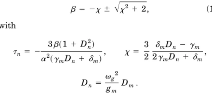
b 5 2x 6
A
x21 2, (11) with tn5 2 3b~1 1 Dn2! a2~g mDn1dm! , x 5 3 2 dmDn2 gm 2gmDn1 dm , Dn5 vg2 gm Dm.The plus in Eq. (11) is used if (gmDn1dm) , 0, and the
minus is used if (gmDn1dm) . 0. This theory does not
account for the full gain-saturation dynamics during the pulse. Instead a steady-state gain saturation is used, and so, the gain gmmay be determined by requiring it to
balance the loss (gm5 1/a 2 1 1 lm).11 It is also
as-sumed that the gain saturation can be described by the formula11
gm5
go
1 1 W/Ws
, (12)
where W5 2A2t is the energy of the pulse and Wsis the
effective saturation energy. The pulse formula given by Eq. (9) states that the pulse is chirped with a chirp pa-rameter b. With the chirp eliminated, the pulse width can be further shortened to
tcm5 t/
A
1 1b2. (13)tcmdenotes the compressed pulse width. The influences of group-velocity dispersion, saturable absorption action, and SPM on the pulse shape are similar to those of the analysis in Ref. 11 because the same master equation is followed. This particularly addresses the significance of the empty auxiliary cavity. Equation (8) shows that the empty auxiliary cavity influences the pulsation situation through three parts: the loss factor (1/a 2 1 1 lm), the
saturable absorption action (a2g
m), and the SPM (a2dm).
The values of these parameters in a reasonable range will be chosen to predict the pulsation of the semiconductor la-sers in the coupled-cavity configuration with an empty auxiliary cavity.
The dispersion parameter Dm is directly proportional
to d2n/dl2, which is in the range of 20–50 mm22 for AlGaAs–GaAs semiconductors.14 A d2n/dl2of 45mm22 is used for the calculation. The loss (lm) is assumed to be
10% to account for the coupling loss from the laser diode to the main cavity. The SPM parameter dm equals
(vo/c)(n2da/Aeff), where n2is the nonlinear index, Aeffis the effective cross section of the mode in the waveguide of the laser diode, and dais the length of the monolithically
integrated absorber, which is 30 mm long in the experiment.8 Because the gain region is externally pumped, the carrier density is kept approximately con-stant. Therefore optically induced changes in the refrac-tive index in response to variations in the carrier density occur mainly in the unpumped absorber, and so the SPM is only considered in the integrated absorber. The value of n2 for semiconductors is estimated to be 1029 cm2/W when the pulse width is much larger than the carrier life time,15which is;400 ps. In the case here, because the pulse is much shorter, the carriers can hardly respond to the pulse, and so n2should be much less than 1029cm2/W
but still larger than 10214 cm2/W for the optical Kerr ef-fect. A medium value that leads to dm; 0.1 W21 is
used.
The description of the saturable absorber as an instan-taneous function of the intensity in Eq. (7) limits this theory to the cases of fast saturable absorbers. It will be shown that use of the instantaneous response of the ab-sorption action could well predict the mode-locked pulses in Ref. 8, indicating that the devices therein might con-tain a fast response of the absorption recovery. Yang and Gopinath16had also concluded from their simulation that a short absorber recovery time is important for the stable operation of passively mode-locked semiconductor lasers. Because the devices in Ref. 8 could be electrically pumped only in pulsed condition, they could possibly suffer the ag-ing effect, and defects might be induced in the operation, leading to fast absorption recovery. Therefore fast ab-sorption recovery is assumed in the model to make the analytical solution possible even with the strongly coupled auxiliary cavity. Even so, the estimation of the value of the saturable absorption actiongmremains
diffi-cult. In the simulation the calculated pulse width gener-ated from the external-cavity laser without the auxiliary cavity dramatically changes with the value of gm. For
gm5 0, the pulse width is larger than the round-trip
time, indicating no pulsation. Increasinggmwill
eventu-ally result in subpicosecond pulses from the calculation. In the experiment of semiconductor lasers with a mono-lithically integrated absorber in an external cavity, but without the auxiliary cavity, the pulse width is approxi-mately between 20 and 30 ps.8 To match this experimen-tal result,gmis approximated as 0.03 W21, which results
in a pulse width of 26 ps under a reasonable assumption of W ; 2pJ17and a gain bandwidth of 30 nm.
With these values applied to the master equation for the coupled-cavity configuration with an empty auxiliary cavity, the pulse width in the steady state is calculated. By varying of the phase shift f2, the calculated pulse width changes periodically as expected. The minimum pulse width is obtained whena is maximum, occurring as f2 is a multiple of 2p. The calculated pulse widths at f25 0 and the corresponding chirp parameters are given in Table 1 for different M2 reflectivities. In the experi-ment the optimal distance between the grating and the retroreflector for pulse compression is not obviously de-pendent on the M2reflectivity, indicating that the chirp of the uncompressed pulses for different M2reflectivities is similar. Table 1 does show that the chirp parameter is almost the same for different M2reflectivities.
Table 1. Calculated Compressed Pulse Widths at f25 0 and Corresponding Chirp Parameters for
Different M2Reflectivities M2 Reflectivity (L3 L) Chirp Parameter b Compressed FWHM (2tcm3 0.88) (ps) 0.2 28.77 0.69 0.3 28.73 0.52 0.4 28.67 0.41 0.5 28.59 0.33
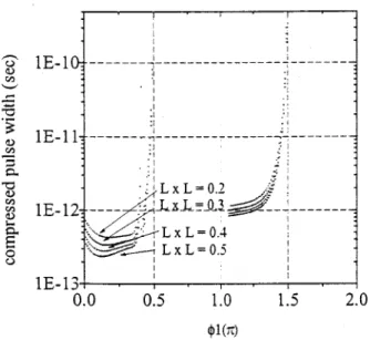
The above analysis shows that in the steady state the empty auxiliary cavity effectively changes the reflectivity a, which equals r without the auxiliary cavity. In addi-tion, the minimum pulse width occurs asf2is a multiple of 2p. The oscillation frequencies for the pulse operation then might be determined by the strongly coupled empty auxiliary cavity. If the linear phase shiftf1in the main cavity deviates from 2mp, the laser parameters in Eq. (8) could be further changed by the multiplication of this lin-ear phase-shift term with those parameters in the first bracket of Eq. (7). Obviously the resulting laser param-eters and the pulsation situation also vary periodically with the phase shift f1. Simulation shows that for f1 slightly more than zero the pulse width is further re-duced. The shortest pulse is approximately at f1 5 0.1p, which is slightly changed by the amount of the feedback from the auxiliary cavity. Very short pulse widths are also obtained forf1 approximately from 0 to 0.3p. Beyond this range, the pulse width increases sig-nificantly. Figure 2 shows the variation of the com-pressed pulse width with the phase shiftf1 for different amounts of the feedback. The pulse widths for f1from ;0 to 0.3p still spread over a certain range, as listed in Table 2. The experiment8 therefore tended to measure pulse widths in this range. The experimental pulse widths from Ref. 8 are also listed in Table 3 for compari-son, which shows that the calculations from the model are in good agreements with the experiments. Figure 2 also shows that another range of relatively short pulses is pre-dicted for f1 sightly more thanp. The second range of short pulses should be expected from Eqs. (1) and (2), which imply that the pulse-shortening effect could occur either in the main cavity or in the auxiliary cavity, as Ak
and Bk have a phase differencep or 2p.
To show that SPM in the main cavity is an important factor for the pulse-shortening effect in the coupled-cavity configuration with an empty auxiliary cavity, different amounts of SPM are applied to simulate the pulsation. If SPM is increased to make dm 10 times larger (dm
5 1 W21), with the other parameters remaining at the same values, the pulse width without the empty auxiliary cavity is approximately the same (32 ps). However, the empty auxiliary cavity could shorten the pulse width to as short as 0.45 ps, and the pulse width could be further re-duced to 30 fs as the chirp is eliminated. A comparison of the pulse widths for dm5 01 W21 and dm5 1 W21
given in Table 4 clearly shows the significance of SPM. In conclusion, mode-locking of semiconductor lasers in a coupled-cavity configuration with an empty auxiliary cavity is studied theoretically. With the empty auxiliary cavity a simple formulation can be obtained for the coupled-cavity configuration even with a strong coupling between the auxiliary cavity and the main cavity. Cal-culations of the minimum pulse widths and the corre-sponding chirp parameters in the steady state, based on this model, are in good agreement with the experimental measurements of mode-locked semiconductor lasers in a coupled-cavity configuration. With the strongly coupled empty auxiliary cavity the shortest pulse width is ob-tained when the phase shift induced by the auxiliary cav-ity is a multiple of 2p and the linear phase shift induced by the main cavity is slightly more than 2mp. The pulses are also expected to be further shortened with in-creasing SPM in the main cavity.
Table 2. Calculated Compressed Pulse Widths for Different Amounts of Feedback from the Empty
Auxiliary Cavity withf1Approximately in the
Range 0–0.3p M2 Reflectivity (L3 L) Compressed FWHM (2tcm3 0.88) (ps) 0.2 0.38–0.69 0.3 0.30–0.52 0.4 0.25–0.41 0.5 0.21–0.33
Table 3. Measured Compressed Pulse Widths for Different M2Reflectivities Device M2Effective Reflectivity (R23 0.64) Compressed FWHM (ps) E-1-12 0.19 0.39–0.70 0.32 0.38–0.66 0.37 0.30–0.49 E-3-12 0.37 0.30–0.51 0.48 0.19–0.42
Table 4. Pulse Widthsa
dm(W21) t1(ps) t2(ps) tcm(ps)
0.1 26 1.25 0.21
1 32 0.45 0.03
at
1, pulse width without the empty auxiliary cavity;t2, pulse width with the empty auxiliary cavity before pulse compression;tcm, pulse width with the empty auxiliary cavity after pulse compression.
Fig. 2. Compressed pulse width versus phase f1for different amounts of feedback from the empty auxiliary cavity.
ACKNOWLEDGMENTS
This work was performed in part at the School of Electri-cal Engineering at Cornell University. C. L. Tang’s sug-gestions are greatly acknowledged. The author also thanks colleagues in Tang’s group and Bor-Lin Lee at the Graduate Institute of Electro-Optical Engineering at the National Taiwan University for their helpful discussions. This work is supported by the National Science Council, Taipei, Taiwan, under contract NSC83-0417-E-002-011.
REFERENCES
1. J. Mark, L. Y. Liu, K. L. Hall, H. A. Haus, and E. P. Ippen, ‘‘Femtosecond pulse generation in a laser with a nonlinear external resonator,’’ Opt. Lett. 14, 48 (1989).
2. C. P. Yakymyshyn, J. F. Pinto, and C. R. Pollock, ‘‘Additive-pulse mode-locked NaCl:OH2 laser,’’ Opt. Lett. 14, 621 (1989).
3. W. Sibbett, ‘‘Hybrid and passive mode locking in coupled-cavity lasers,’’ Ultrafast Phenomena 7, 2 (1990).
4. P. M. W. French, S. M. J. Kelly, and J. R. Taylor, ‘‘Mode locking of a continuous-wave titanium-doped sapphire laser using a linear external cavity,’’ Opt. Lett. 15, 378 (1990). 5. P. G. Wigley, P. M. W. French, and J. R. Taylor, ‘‘Mode
lock-ing of a continuous wave neodymium doped fiber laser with a linear external cavity,’’ Electron. Lett. 26, 1283 (1990). 6. Y. Shi, C. V. Poulsen, M. Sejka, and O. Poulsen,
‘‘Mode-locked Pr31-doped silica fiber laser with an external cavity,’’ J. Lightwave Technol. 12, 749 (1994).
7. C. C. Cutler, ‘‘Why does linear phase shift cause mode lock-ing?’’ IEEE J. Quantum Electron. 28, 282 (1992).
8. C. F. Lin and C. L. Tang, ‘‘Generation of ultrashort pulses from a superluminescent diode with a monolithically inte-grated absorber in a coupled-cavity configuration,’’ Appl. Phys. Lett. 63, 2594 (1993).
9. K. J. Blow and David Wood, ‘‘Mode-locked lasers with non-linear external cavities,’’ J. Opt. Soc. Am. B 5, 629 (1988). 10. E. P. Ippen, H. A. Haus, and L. Y. Liu, ‘‘Additive pulse
mode locking,’’ J. Opt. Soc. Am. B 6, 1736 (1989).
11. H. A. Haus, J. G. Fujimoto, and E. P. Ippen, ‘‘Structures for additive pulse mode locking,’’ J. Opt. Soc. Am. B 8, 2068 (1991).
12. W. H. Loh and C. F. Lin, ‘‘Optical pulse generation with a semiconductor laser in a coupled-cavity configuration,’’ Pure Appl. Opt. 1, 181 (1992).
13. G. H. C. New, ‘‘Self-stabilization of synchronously mode-locked lasers,’’ Opt. Lett. 15, 1306 (1990).
14. Y. Silberberg and P. W. Smith, ‘‘Subpicosecond pulses from a mode-locked semiconductor laser,’’ IEEE J. Quantum Electron. 22, 759 (1986).
15. G. P. Agrawal and N. A. Olsson, ‘‘Self-phase modulation and spectral broadening of optical pulses in semiconductor laser amplifiers,’’ IEEE J. Quantum Electron. 25, 2297 (1989).
16. W. Yang and A. Gopinath, ‘‘Study of passive mode locking of semiconductor lasers using time-domain modelling,’’ Appl. Phys. Lett. 63, 2717 (1993).
17. D. J. Derickson, R. J. Helkey, A. Mar, J. R. Karin, J. E. Bowers, and R. L. Thornton, ‘‘Suppression of multiple pulse formation in external-cavity mode-locked semiconductor la-sers using intrawaveguide saturable absorbers,’’ IEEE Pho-tonics Technol. Lett. 4, 333 (1992).