Proceedings Of the 2OOO IEEE International Conference on Robotics 8 Automation
San Francisco, CA April 2000
DSP-Based Controller for a Multi-Degree Prosthetic Hand
Han-Pang Huang* and Chun-Ying Chiang**
Robotics Laboratory, Department
of Mechanical Engineering
National Taiwan University, Taipei 10660, TAIWANTeVFax: (886) 2-26363875
*Professor and correspondence address **Graduate student
Abstract
The electromyographic (EMG) signal is used to discriminate eight hand motions: power grasp, hook grasp, wrist flexion, lateral pinch, flattened hand, centralized grip, three-jaw chuck and cylindrical grasp. From the analysis of the PC-based control system, a three-channel EMG signal is used to distinguish eight hand motions for the short below elbow amputee. Pattern recognition is used in this discriminative system. Three surface electrodes are placed on palmaris longus, entensor digitorum and flexor carpi
ulnaris. Due to the complexity of the EMG signal and the portable consideration of the controller, a controller based on digital signal processor (DSP) is designed and implemented in this discriminative system. The DSP integrates the signal preprocessing module, the digital filter module and pattern recognition module into the controller. The on-line DSP controller can provide 87.5% correct rate for the discrimination of eight hand motions.
Keywords: EMG prosthetic hand, digital signal processor, pattern recognition
I. Introduction
The myoelectrically controlled prostheses provide amputees extra prosthetic options. However, most commercial prosthetic hands (e.g. Steeper Electric Hand, Otto Bock System Electric Hand, Swedish Systemteknik Hand) [2] are one degree of freedom grippers that are controlled by one or two channel of electromyographic (EMG) signals. Their surface electrodes were placed on the antagonist muscles. When the muscle tension reaches a threshold value, the prosthetic hands generate a digital
o d o f f switch to control a motor to direct the hand in one direction or another. An alternate way is simple proportional controi in terms of EMG signal [14]. The proportional control provides the user less sensitive and more fast control of the hand, depending on the strength of muscle contraction. Proportional myoelectric control has been used in the
Utah
artificialarm [SI.
Those EMG controlled systems mentioned above limit the ability of manipulation. Recently a number of advanced dexterous robot hands have been successfully developed. A few of them can be used in prosthetics [7,11]. A modular prosthetic hand was developed by [ 5 ] . They are multi- fingered prosthetic hand capable of performing a variety of prehensile postures, including different grasp modes (e.g.power grasp, hook grasp cylindrical grasp, three-jaw chuck etc.). Nevertheless, how to control a multi-functional prosthetic hand using EMG signal is the most difficult problem.
The human hand is a complex and amazingly versatile system. For performing dexterous tasks, the hand depends on control inputs fiom the central nervous system (CNS) and numerous sensors that provide feedback. If a specific task is defined, the hand is preshaped into a posture suitable to grasp the object, and then encloses the object [6]. The dexterous hand control has complex interaction between the hand and the object. Task level planning simplifies the process of controlling the dexterous hand [12]. The grasp planning involves in selecting a grasp posture for the dexterous hand and determining a trajectory planning so that the hand contacts and approaches the object. A grasp posture is in terms of a grasp mode. If the grasp mode is defined, the preshaping controller determines the preshaping posture for the prosthetic hand and the enclosure controller closes the hand until the desired grasp forces are achieved. Once EMG signal can be recognized as one of the eight hand motions, the relevant preshaping motion of the prosthetic hand can be determined. The complex discriminative system will be discussed in this paper. For consideration of real-time performance, the complex algorithms of the discriminative system will be implemented in a DSP (digital signal processor) system.
11. EMG
Discriminative System
1. EMG Signal ProcessingThe upper extremity has two main functional parts: the terminal prehension device (hand/wrist) and a crane system (andshoulder). The basic function of the terminal device is to provide the proper grip for functional activities. Prehension is one of the primary functions. In this paper, eight types of prehensile postures are selected from [3] for study.
In order to choose meaningful EMG signals for eight kinds of prehensile postures, the location of electrodes is important. According to the relations between the muscle locations and the prehensile postures [9], three channel electrodes are placed on palmaris longus, entensor digitorum and flexor carpi ulnaris. In other words, we focus on short below elbow disarticulation.
The surface electrodes used for EMG signals are manufactured by B & L Engineering in U.S.A. The B & L Active Electrode is available with an integrated ground. Though the surface EMG signal has been magnified in the electrode system, the output EMG signal is only about -0.2 to 0.2 V (peak-to-peak). In order to avoid the distortion of converting from the analog EMG signal to digital signal, the EMG signal is further amplified about twenty times using an operational amplifier. The signal-preprocessing module is composed of the amplifier and analog filter circuit in a PC-based system [3]. In the DSP-based controller, the module only needs the amplifier circuit. For reducing the weight of a myoelectric controller, the digital filter will be implemented in a TMS32OC3 1 DSP to replace the analog filter circuit.
2. Pattern Recognition
(1) Feature Extraction
Surface EMG signals are nonlinear and stochastic. They are contributed by the summation of triggered motor units with respect to the measuring electrode location. Thus, different motions create different myoelectric signals with different characteristics. In this paper, the features of myoelectric signals are calculated from time series and spectral parameters. Several kinds of features are used to represent the myoelectric signal patterns. They are given below.
Integral of EMG (IEMG): This is an estimate of the summation of absolute value of the EMG signal. It is given bY
where x is the k th sample data which has N samples raw data.
Waveform Length (WL): This is a cumulative variation of the EMG signal that can indicate the degree of variation about the EMG signal. It is given by
K - I
Variance
(VAR):
This is a measure of the power density of the EMG signal, and is given byZero Crossings (ZC): This parameter counts the number of times that the signal crosses zero. A threshold needs to be introduced to reduce the noise induced at zero crossings. Given two continuous data xk and the zero crossing can be calculated as
zc =
2
[’@(- xk xk+]) IXk - xk+d‘
“021 r - lif x > o
’@!
) ={
i’,
otherwise (4)Slope Sign Changes: This parameter counts the number of times the slope of the signal changes sign. Similarly, it needs to include a threshold to reduce noise
induced at slope sign changes. Given three continuous data
x,-,, x k and x,,,, the number of slope sign change increases if
k,
-xt-I)x
&,
-xk+,)
2 0 03 for R = 1. ..., N ( 5 )Willison Amplitude (WAMP): It is the number of counts for each change of the EMG signal amplitude that exceeds a pre-defined threshold. It can indicate the muscle contraction level, and is given by
(6)
HXMp =
f
f ( l x t - x t + 1 0 1 . 1If x > 0 . 3
( x ) =
[
i;
otherwiseThe above six parameters are extracted according to Eqns. (1) to (6). The first three parameters are time-domain calculation and all floating-point type. The last three parameters are rough frequency measure and all integer type. Hence, six parameters are divided into two groups: three floating point Parameters and three integer parameters.
Autoregressive (AR) Model: It is difficult to analyze the EMG signal for its nonlinear and nonstationary nature. But in a short time interval the EMG signal can be regarded as a stationary Gaussian process. Graupe et al. [4] addressed a linear model for a Gaussian process. They used a pure autoregressive (AR) model to identi@ the EMG time-series as
Y & =
- f
, - Ia
I~ t - l + a kwhere y , is the EMG time series, and
k is the interval.
N is the order of AR model, a , are the estimate of the AR parameters, and CO, is the white noise. A least squares method that minimizes the s u m of squared CO, is used to obtain the parameters of the signal model.Cepstrum Analysis (c(t)): Cepstrum analysis is concerned with the deconvolution of two signal types that are the basic wavelet and the impulse signal. It can be defined as the inverse Fourier transform of the logarithm of the magnitude of the power spectrum of the signal data [l]. It can be represented as
(7)
1 “ (8)
c ( r ) =
2n j
-.
In [X ( e l * ) ] e ~ * a d o (2) Feature SelectionThe success of any pattern recognition system depends on the choice of features used to represent the continuous time waveforms. In feature extraction stage, eight kinds of parameters of the EMG signal are extracted. The parameters are splitted into four groups: three integer parameters group, three floating-point parameters group, AR model parameters group and cepstrum parameters group. They are combined with each other in classification stage to find the highest classification rate in the PC-based discriminative system. A set of features that have the highest classification rate in the PC-based system is then implemented in the DSP-based controller.
(3) Classification by Neural Network
The parameters extracted from the feature selection stage can be used to separate different input patterns into different output classes. It needs a powerful classifier to solve the nonlinear discriminative system of the EMG signal. We adopt the backpropagation neural nehvork (BPNN) as the classifier [13]. The classifier has one hidden layer and the entire system is a three-layer perceptron. The gradient steepest descent method is adopted to solve the minimization error of each input pattern.
111.
DSP-based Prosthetic Controller
The pattern recognition is implemented in the DSP- based prosthetic controller system. To reduce the computation time, a high performance processor, Texas Instruments TMS320C31 DSP, is selected as the kernel of the entire prosthetic controller. For saving the time to develop the prosthetic controller system, a 'C3x DSP starter kit (DSK) is adopted. The DSK is a low-cost, easy- to-use, and expandable development platform. The DSK has a TMS320C3 1-60 on board to handle signal-processing applications.1. Hardware Architecture of the Controller
The development of hardware architecture can be divided into two stages: the off-line stage and the on-line stage. In the off-line stage, the approximate initial weights of the neural network for each amputee are obtained. While in the on-line stage, the weights are finely tuned for the same amputee to gain high performance classification rate.
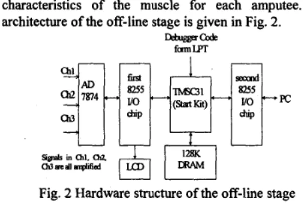
(1) The Off-line Stage of the Prosthetic Controller Because every amputee has different characteristics of the muscle, the hand motions must be learned before the controlIer is used. In this stage, the most important thing is to train the amputee to perform eight prehensile motions. Initial weights can be obtained to represent the characteristics of the muscle for each amputee. The architecture of the off-line stage is given in Fig. 2.
D$ugga-
fcrmw
I
si@ in al l , m
aowalldfird
pkl
1
z
1
Fig. 2 Hardware structure of the off-line stage
(2) The On-line Stage of the Prosthetic Controller This stage has on-line learning mode and on-line testing mode. A 4x4 keyboard is used to input the learning goal for on-line learning. After on-line learning, the controller changes to the on-line testing mode. The amputee can control the prosthetic hand directly in this
mode. If the controller has bad recognition rate, it can change back to the on-line learning mode for another trainning. Fig. 3 is the hardware structure of the on-line stage.
SlgnalS 10 al. Chz, Ch3 lue all ampkfied
Fig. 3 Hardware structure of the on-line stage 2. The Software System of the Controller
The software development tools are TMS32OC3dC4x AssemblerLinker and 'C3x DSK Debugger supported fiom Texas Instruments. The entire software system is composed of four main parts: EMG signal collection, signal processing, feature extraction and BPNN classification.
(I) Signal Collection
After amplifying EMG signal twenty times using an operational amplifier, the controller is then developed by DSP code. First, when the ADC chip receives the amplified EMG signals, the EMG signals are converted into digital style. For getting the stable EMG signals, about 1000 points within 300400 ms are collected. The sampling rate is about 0.4ms. However, it is difficult to detect the starting of the muscle contraction. The IEMG was applied well and confidently in many papers [3,10].
Thus,
we select the average IEMG as the criterion to verify the muscle contraction for canceling the unstable noise. The average IEMG value of 25 ms raw window length is calculated to judge whether the muscle contracts or not. A bias is added to the threshold of the muscle contraction according to the surrounding environment noise. Because the computation time of DSP is faster than 25 ms raw EMG signal, the raw EMG window can be regardedas
a continuous series of 25 ms raw window. When the average IEMG value exceeds the pre-defined threshold, 1000 running EMG data are collected. It also can be illustrated by the following equation.(9)
1 1.N
'i,
f 'EMG=N
C l X , l >
T,,X , = collect EMG raw daia for analyzing I = 1 to lo00 where N = windows lengih ; T,, : ihreshold wlue
(2) Signal Processing
After collecting 1000 points EMG data, the primary thing is to filter the uncertain signal. The bandwidth of the EMG signal is about 30-400 Hz in previous research and the environment noise are about 60 Hz. Thus; a bandpass filter with bandwidth from 30Hz to 400Hz and a 60
Hz
notch filter is designed using Butterworth type filter. Often the infinite impulse response (IIR) filters are more efficient in getting better magnitude response for a given filter order. In other words, IIR filter can
run
faster in lower filter order. The Matlab software is used to design the Butterworth IIR digital filter. The resultant filter is shown below.0 30Hz to 400Hz Butterworth bandpass filter
The system transfer function of a sixth-order badpass filter is designed by
0.0479466 -0.143838' + 0.143838' - 0.047946
z6 -4.015503' +67835754 -6.3222" +3.50323F -1.090804+0.141%5 -
The sampling period is 0.4 ms.
0 60Hz Butterworth notch filter filter is designed by
The system transfer function of a fourth-order notch
- z' - 3.962' + 5 9256 z 2 - 3.970296 z + 1.00520676
z' - 3.92z3+ 5.8045 z 2 - 3.847284 z + 0.963242
The sampling period is also 0.4 ms.
Because the bandpass and notch filter function are both linear systems, they can be combined to form a tenth-order filter that includes their characteristics. The transfer function of the augmented system can be written as
The designed filters are coded in DSP algorithm. For reducing memory requirement and sensitivity of quantization coefficient, both bandpass filter and notch filter are used rather than the tenth-order filter. These two filters are configured in cascade structure. The connected canonical-form structure equation of the filter is given as
sred. k = 1 Ak- 5 nl = dnl
4k,n] = q&c- Sn] + a;Mk,n -11 +%Hfk,n -21
+
..
.+o&k,n-6] Y[k,n] =$4k, n] + 4kMk,n - 11 + &4k,n-2] +. ..+ b,w[k,n -61steji?.k=2
4 k n l = Q.k - Sn] + a ; 4 k , n - 11 + f&.[Sn
-
21 +. . .+u,w&I-
41 Ak,n] = 4 4 k , n ] + 4*4k,n-
11 + b&k,n -21+.
. .+ b,Mk,n -41 An1 = k. nlThe fiequency response of the desired filter H ( Z ) is
shown in Fig. 4. It posseses the combined characteristics of both the bandpass filter and the notch filter.
(3) Feature Extraction
The features of the EMG signal for each channel are extracted from the filtered EMG signals. For the controller design, the features are selected fiom the PC-based analysis [3]. Figure 5 shows the correct rate for different parameter groups. The 4th-order AR parameters group plus three integer parameters group and three floating-point parameters group can represent the meaningful features of the EMG signals for each case.
(13)
Line: MaUab simulated : Dashed line: DSP lmslemented
Frequency (Ha
Fig. 4 Frequency response comparison of H ( z )
Fig. 5 Comparison of correct rate with different parameter group
In this controller, those best-combined features are selected
as the EMG signal features. It turns out that ten parameters for each channel signal and thirty parameters for each motion type are obtained. These thirty parameters are input vectors for BPNN. It is shown in Table 1.
Table 1 Number of parameters in the controller
(4) BPNN Classification
The BPNN algorithm mentioned before is coded in assembly language. The BPNN is three-layer architecture with input layer, hidden layer, and output layer. The number of the hidden layer node is determined according to PC-based analysis. Here, 15 nodes are used for the hidden layer. The input layer has 30 nodes for representative features of each motion. The output layer has 8 nodes for discriminating eight motions. The neural network off-line learns the initial weights and maximudminimum values of each input vector. Then, it is on-line implemented in DSP.
The on-line stage of the system consists of learning mode and testing mode. In the on-line learning mode, the user must perform the motion and go through the desired learning motion. After finishing the learning mode, the program is switched to the testing mode. In the testing mode, the user can perform any of eight motions to control the prosthetic hand directly. If the user has problems in controlling the prosthetic hand, it can be changed back to
the learning mode to improve the classification rate of the controller in any time.
IV.
Implementation and Results
of
the
DSP-based Controller
The implementation of the DSP-based system is also divided into two stages: off-line learning stage and on-line testing stage. The off-line learning stage is used to get the initial weight, the initial bias values and extrema of input vectors for neural network classification. The types of input vector are defined in Table 1. They can be regarded as the EMG signal characteristics of the user. The on-line testing stage is used to control the prosthetic hand according to the neural network built in the off-line stage. Each hand motion is trained 20 times (off-line learning stage), and tested
IO
times (on-line testing stage). The Dicture of the controller is shown in Fig. 6.Fig. 6 DSP-based myoelectric controller box
1. Off-line Stage Implementation
The locations of the three-channel electrodes are shown in Figure 7. Each hand-motion is learned twenty times. The features of three-channel EMG signals are calculated by DSP chip and sent to PC to
run
BP neural network to get the initial weight, the initial bias values and extrema of the input vectors. Each feature is normalized so that each input vector have the same range for training in the neural network. The neural network has 30 input nodes,15 hidden layer nodes, and 8 output nodes.
Upon finishing off-line learning stage, the initial weight, the bias values and extrema of the input vectors of the neural network are downloaded into SRAM, and the system is changed to the on-line testing stage.
2. On-line Stage Implementation
After the off-line learning stage, the system performs the on-line stage and serves as a prosthetic controller. In
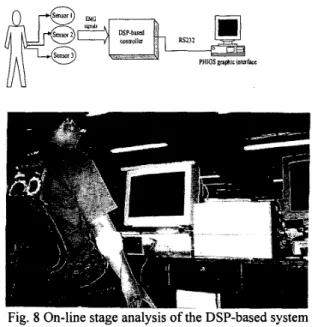
the on-line stage, the on-line learning feature can improve the controller correct rate. Different situation of the muscles and different noise of environment affect the variation of the EMG signals. The neural network must be adjusted to get better performance. In the on line stage, the controller is used to control the graphic NTU-hand [ l l ]
Fig. 7 Locations of surface electrodes
Fig. 8 On-line stage analysis of the DSP-based system
3. On-line Analysis Results
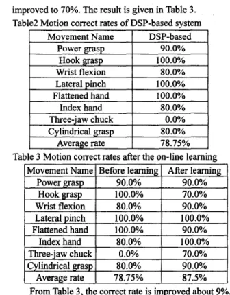
Each hand motion is tested IO times (on-line testing stage). The controller uses the best-combined features as EMC features. The correct rate of the entire system is shown in Table 2. Note that the three-jaw chuck motion is always classified as a lateral pinch. These two hand- motions do look like each other and imperceptible. Because the training times for the off-line stage is not long enough, we push key ‘L’ to run the on-line learning stage. Each motion is learned five more times. After the on-line learning stage, the correct rate of three-jaw chuck is
improved to 70%. The result is given in Table 3. Table2 Motion correct rates of DSP-based system
Powergrasp
I
90.0%Table 3 Motion correct rates after the on-line learning 90.0%
From Table 3, the correct rate is improved about 9%. It is clear that the on-line learning stage can update the weight and the bias values to improve the controller performance. The above results show that the DSP-based controller successfully discriminate eight hand motions.
V.
Conclusion
In this paper, The DSP-based system integrates the signal preprocessing module, the digital filter module and pattem recognition module into the DSP. The DSP-based controller is portable and compact. Furthermore, the on- line learning hnction is capable of improving the classification rate. After on-line learning, the correct rate of
the controller can be up to 87.5% in one-line testing. Note that the best-combined feature is selected
as
the input vector of the EMG signals and the BPNN as classifier in both the PC-based and DSP-based systems.Acknowledgement
This work is partially supported by National Science Council under Grant number NSC 89-22 12-E-002-066.
References
M. Akay, Biomedical Signal Processing, San Diego: Academic Press, 1994.
D.J. Atkins and R.H. Meier 111, Comprehensive Management of the Upper-Limb Amputee, Springer- Verlag New York Inc., 1989.
[3] C.Y. Chen, “Development of a Myoelectric Controller for a Multi-Degree Prosthetic Hand,” Master Thesis, Department of Mechanical Engineering, National Taiwan University, 1998.
[4] D. Graupe, J. Magnussen and A.A. M. Beex, “A Microprocessor System for Multifunctional Control of Upper Limb Prostheses via Myoelectric Signal Identification,” IEEE Transactions on Automatic Control, Vo1.23, No. 4, pp. 538-544, 1978.
[SI L.T. Han, “Development of A Modular Prosthetic Hand: NTU-Hand 111,” Master Thesis, Department of Mechanical Engineering, National Taiwan University, 1998.
[6] T. Iberall, G Sukhatme,
D.
Beattie and G.A. Bekey, “Control Philosophy and Simulation of a Robotic Hand as a Model for Prosthetic Hands,” Proceedings of IEEE International Conference on Intelligent Robots and Systems, V01.2, pp. 824 -83 1, 1993 [7] T. Iberall, GS. Sukhatme, D. Beattie and GA. Bekey,“On the Development of EMG Control for a Prosthesis Using a Robotic Hand”, Proceedings of IEEE International Conference on Robotics and Automation, [8] S.C. Jacobsen, D.F. Knutti, R.T. Johnson and H.H.
Sears, ”Development of the Utah Artificial Arm,” IEEE Transactions on Biomedical Engineering, BME- [9] F.P. Kendall, E.K. McCreary and P.G Provance, Muscles Testing and Function: with Posture and Pain, Baltimore, Md. : Williams & Wilkins, 1993.
[lo] C.H. Kuo, “The Development of a Controller for Artificial Arm via EMG Pattern Recognition,” Master Thesis, Department of Electrical Engineering, National Taiwan University, 1995.
[l 11 L.R. Lin and H.P. Huang, “Mechanism Design of A New Multifingered Robot Hand,’’ Proceedings of IEEE International Conference on Robotics and Automation, V01.2, pp. 1471 -1476, 1996.
[12] H. Liu, T. Iberall, G.A. Bekey, “The multi-dimensional quality of task requirements for dextrous robot hand control,” Proceedings of IEEE International Conference on Robotics and Automation, Vol. 1, pp. 452 -457, 1989.
[13] D. Rumelhart, GE. Hinton, R.J. Williams, “Learning internal representations by error propagation,” Rumelhart DE, McClelland
JL
(Eds.): Parallel Distributed Processing, Cambridge, MA: MIT Press, [14] H.H. Sears and J. Shaper”, “Proportional Myoelectric Hand Control: An Evaluation,” Amer. J. Physical Med. And Rehab, V01.70, No.1, pp. 20-28,1991.V01.2, pp. 1753 -1758, 1994.
29, NO.4, pp. 249-269, 1982.