A
1.5V
Bootstrapped Pass-Transistor-Based Carry Look-Ahead Circuit
Suitable for Low-Voltage CMOS VLSI
J. H. Lou and J. B. Kuo
Rm. 338, Dept. of Electrical Eng., National Taiwan University Roosevelt Rd., Sec. 4, #1, Taipei, Taiwan 106-17
Abstract-This paper reports a 1.5V bootstrapped
pass-transistor-based carry look-ahead circuit suitable for CMOS VLSI using a low supply voltage. With the bootstrapped technique, the speed performance
of a 4-bit carry look-ahead circuit can be enhanced by
70% at a supply voltage of 1.5V as compared to the
conventional Manchester carry look-ahead circuit.
4 c3
I.
INTRODUCTION
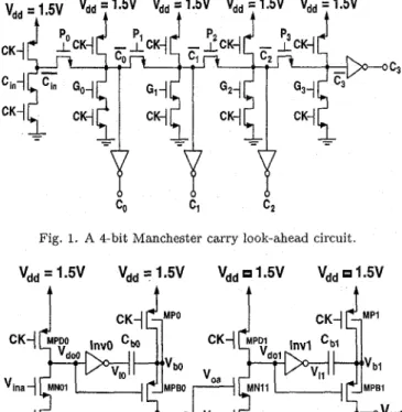
CMOS Manchester carry look-ahead circuit as shown in Fig.1 based on pass transis tors and dynamic logic techniques [I]-[4] have been used to implement arithmetic circuit. With the pass transistor configuration, Manch- ester CLA circuit has the smallest transistor count among all CLA circuits including domino and other static tech- niques [1]-[4]. The function of the MCLA circuit is:
C, =
Gi
+
Ci-1 P,, f o r i = 1 N n, where n is the bit number, Gi andPi
are the generate and propagate signals (Gi =Xi.
Y,, Pi =X,
@x)
produced from two in- puts(Xi,
Y,)
to the half adder. In the MCLA circuit, each bitcarrlJ
signal(G)
is low if the generate signal (G,) is high or if the propagate signal ( P z ) is high and the E T i F j J signal of the previous bit(G)
is low. When the carry look-ahead chain is long, as in a 64-bit adder, the ripple- carry propagation delay becomes unacceptable due to theRC
delay of the pass transistor [3][4]. In other words, the density advantage of theMCLA circuit is offset by the drawback in the speed. This is especially serious when the supply voltage is scaled down, which is a trend for deep-submicron VLSI. In this paper, a high-speed 1.5V bootstrapped pass-transistor-based carry look-ahead cir- cuit suitable for low-voltage CMOS VLSI is described.11. T H E 1.5V BOOTSTRAPPED
PASS-TRANSISTOR-BASED CARRY LOOK-AHEAD CIRCUI T
Fig.2 shows a two-stage 1.5V CMOS bootstrapped dy- namic logic (BDL) circuit, which is composed of the CMOS dynamic logic circuit and the CMOS bootstrap- per c ircuit [5]. As shown in the figure, MPD, MND,
This work is supported under R.O.C. National Science Council Contracts #84-2622-E002-008, 011 & #85-2215-E0002-024.
Fig. 1. A 4-bit Manchester carry look-ahead circuit.
vdd = 1.5V vdd = 1.5V vdd 1.5V vdd 1.5V
t
t
t
t
I
CK-/cMPo
Fig. 2. The 1.5V CMOS bootstrapped dynamic logic (BDL) circuit including the CMOS bootstrapper circuit.
MN1, and MN2 comprise the dynamic logic circuit. The CMOS inverter- Inv, MP, MPB, and the bootstrap ca- pacitor Cb form the bootstrapper circuit. The operation of the CMOS bootstrapped dynamic logic (BDL) is like conventional domino logic, except for that the output of the CMOS bootstrapper is bootstrapped to over ?DO). The function of the bootstrapper circuit will be explained in detail later.
Fig.3 shows the 1.5V bootstrapped pass-transistor- based carry look-ahead circui t. As shown in the fig- ure, the bootstrapper circuit [5], which functions as an inverter, is used to boost the input signal to the gate of the pass transistors. When the input to the bootstrapper circuit is high, MPB is off and MN is on. Therefore, the output of it is pulled low to ground. At the same time, VI is low, hence MP is on and V b is pull high to V&. At
this time, the bootstrap transistor M P C , which is made of a PMOS device with its source and drain tied together,
Fig. 3. (a) Block diagram of a 4-bit carry look-ahead circuit. (b) The CLA cell using 1.5V bootstrapped pass-transistor-based circuit.
1 8 .
1 6 .
-
1 4 .stores an amount of
(Vdd
-
I V T P ~ ) C ~ ~ W L
charge, whereC,, is unit area gate oxide capacitance (Coz = e o z / t o z ) ,
and VTP is the threshold voltage of the PMOS device.
When the input switches from high to low, MN turns off and MPB turns on. Meanwhile,
VI
changes to high and MP turns off. Since the bootstrap transistor MPC turns off, the evacuated holes from the channel of the PMOS de- vice will make vb go up to exceedVdd-
the internal volt- age overshoot. Consequently, the output (Pi) will also go up to surpassVdd.
The voltage overshoot at the output of the bootstrapper circuit enhances the speed performance of the pass-transistor-based carry look-ahead circuit ow- ing to the extra gate overdrive voltage. The advantages of the bootstrapper circuit are especially noticeable for the low supply voltage applications.V,, P 1 9
Fan Out I 2 , ~ ' Dynamlc
Manchester CLA ,
Fig.4 shows the transients of the 4-bit carry look-ahead circuit using the 1.5V bootstrapped pass-transistor-based circuit and without. As shown in the figure, with the bootstrapper circuit, during the transient, the Po signal to gate of the pass transistor can surpass 1.5V. As a re- sult, the pass transistor can turn on eariler as compared to the one in the conventional Manchester carry look-ahead
z
g 1
p) 1.5-
P
0.5 0 i i 8 8 rb i 2 1'4 1'6A
Time (ns)s
-
p) 1.5-
P
S '
0.5 0 G(condntiona1)4'51
i i 8 8 Ib i 2 1'4 1'6 l'8 Time (ns)Fig. 4. Transients of the 4-bit carry look-ahead circuit (a) with and (b) without the 1.5V bootstrapped pass-transistor-based circuit.
circuit. Consequently, a higher speed can be expected for the carry look-ahead circuit with the bootstrapper cir- cuit. Fig.5 shows the delay time versus bit number of the carry look-ahead circuit using the 1.5V bootstrapped pass-transistor-based circuit and without. As shown in the figure, a consistent improvement in speed can be seen for the CLA with the bootstrapped pass-transistor-based circuit. At 8 bits, the speed enhancement is 2.1 times.
20, I
Manchester CLA
Fig. 5. Delay time versus bit number and of the carry look-ahead cir- cuit using the 1.5V bootstrapped pass-transistor-based circuit and without.
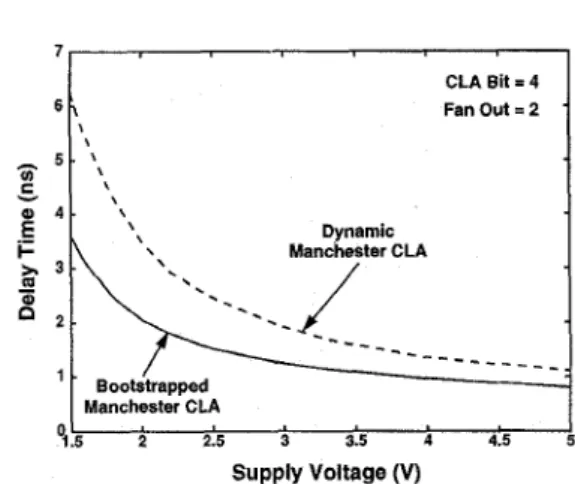
7 CLA Bit = 4 FanOut=2 . 6 , 1
’
-
5 .’\
, t \ Y Dynamic Manchester CLA ,--
L/
- - -
- - -
- _ _ _ _ _ _
*.g
4 . \ \-
% 3 .8
2 . .- I-’
. Bootstrapped 01.5 i 215 i 3:s i 4:5 Manchester CLAFig. 6. Delay time versus supply voltage of the carry look-ahead cir- cuit using the 1.5V bootstrapped pass-transistor-based circuit and without.
4, pp. 329-332, Apr. 1994.
LOU and J. B. Kuo, “A 1.5V Full-Swing Bootstrapped CMOS Large Capacitive-Load Driver Circuit Suitable for Low- Voltage CMOS VLSI,” IEEE J . Solid-state Circuits, Vol. 32, [SI J .
REFERENCES
[l] N. H. E. Weste and K. Eshraghian, “Principles of CMOS VLSI Design,” Addison Wesley: New York, NY, 1985.
[2] J . Kernhof, M. A. Beunder, B. Hoefflinger, and W. Haas, [‘High-speed CMOS Adder and Multiplier Modules for Dig- ita1 Signal Processing in a Semicustom Environment,” IEEE J . Solid-state Circuits, pp. 570-575, June 1989.
[3] J . B. Kuo H. J. Liao and H. P. Chen, “A BiCMOS Dynamic Carry Look-Ahead Adder Circuit for VLSI Implementation of High Speed Arithmetic Unit,” IEEE J . Sold-State Circuits,
pp. 375-378, Mar. 1993.
[4] J. B. Kuo, S. S. Chen, C. S. Chang, K. W. Su, and J. H. Lou, “A 1.5V BiCMOS Dynamic Logic Circuit Using a “BiP-
s
III. DISCUSSION
The bootstrapped pass-transistor-based carry look- ahead circuit is especially advantageous for low supply voltage applications. Fig.6 shows the delay time versus supply voltage of the 4-bit carry look-ahead circuit using the 1.5V bootstrapped pass-transistor-based circuit and without. As shown in the figure, at a supply voltage of 1.5V, the improvement is 1.7 times.
IV. CONCLUSION
No. 1; pp. 119-121, Jan. 1997.
In this paper, a 1.5V bootstrapped pass-transistor- based carry look-ahead circuit suitable for CMOS VLSI using a low supply voltage has been reported. With the bootstrapped technique, the speed performance of a 4-bit carry look-ahead circuit can be enhanced by 70% at a supply voltage of 1.5V as compared t o the conventional Manchester carry look-ahead circuit.