Determination of optical parameters of a
twisted-nematic liquid crystal by phase-sensitive
optical heterodyne interferometric ellipsometry
Chien-Chung Tsai, Chien Chou, Chien-Yuan Han, Cheng-Hung Hsieh, Kuo-Yu Liao, and Yu-Faye Chao
What is believed to be a novel phase-sensitive optical heterodyne interferometric ellipsometer is set up to characterize a twisted-nematic liquid crystal (TN-LC) by the elliptical parameters of the output polarization state. This ellipsometer presents the advantages of both polarized optical heterodyne inter-ferometry and optical photometry, which introduce a polarization modulation that is capable of perform-ing with high-sensitivity on phase detection in real time. The twist angle⌽ and the untwisted phase retardation⌫ of TN-LC are measured precisely. The experimental results verify that a TN-LC can be treated as identical to an elliptical retarder. © 2005 Optical Society of America
OCIS codes: 120.2130, 120.3180, 120.5240, 120.5410, 160.3710.
1. Introduction
The optical properties of an anisotropic material can generally be divided into linear birefringence (LB) and circular birefringence (CB).1,2LB results from different
phase velocities of two orthogonal linear-polarization eigenstates in material.3In contrast, CB is caused by
different phase velocities of two orthogonal circular polarization eigenstates in the medium.4However, an
anisotropic material, such as a twisted-nematic liquid crystal (TN-LC), shows its optical properties of LB and CB at the same time.5,6 Then a pair of orthogonal
elliptical polarizations becomes the eigenpolarizations of the TN-LC. In other words, a TN-LC5,7–13 can be
treated as an elliptical phase retarder theoretically. Therefore the optical properties of a TN-LC can be characterized in view of the elliptical birefringence by means of the phase retardation␥ of the elliptical eigen-polarizations and the elliptical angleεproduced by two linearly polarized P and S waves of each elliptical po-larization eigenstate emerging from the TN-LC. In the
meantime, the untwisted phase retardation (which is related to cell thickness), twist angle, and the entrance orientation of molecular direction (the director angle) of a twisted-nematic cell are of great importance for LC display applications because those parameters are closely related to the optical quality of LC display de-vices.14The poor uniformity of cell thickness results in
a decrease in picture quality. These parameters are usually determined from measuring the intensity transmittance of the TN-LC device sandwiched be-tween two polarizers and from curve fitting of the the-oretical prediction based on a Jones matrix to experimental data. However, a twist angle with 180° ambiguity and a director angle with 90° ambiguity resulted from this approach.15 Kim and Lee16
pro-posed a method of curve fitting by the Jones matrix to measure the TN-LC parameters with no ambiguity by measuring the intensity transmittance with and without a quarter-wave plate. In this paper, we pro-pose what we believe to be a novel method in which only the phase retardation between orthogonal lin-early polarized P and S waves emerging from the TN-LC in the polarized optical heterodyne inter-ferometer is detected by a lock-in amplifier. This method is different from conventional methods that rely on intensity detection by a photometric tech-nique to determine TN-LC parameters.6,9,14 In
con-trast, phase detection by this optical heterodyne interferometry has the advantage of avoiding the am-biguities of twist angle and entrance director angle of a TN-LC. In addition, the detection sensitivity of
C.-C. Tsai, C. Chou, C.-H. Hsieh, and K.-Y. Liao are with the Institute of Biophotonics Engineering, National Yang-Ming Uni-versity, Taipei, Taiwan 112; C. Chou ([email protected]) is also with the Institute of Radiological Sciences at National Yang-Ming University. C.-Y. Han and Y.-F. Chao are with the Institute of Electro-Optical Engineering, National Chiao-Tung University, Hsinchu, Taiwan 300.
Received 9 May 2005; accepted 23 June 2005. 0003-6935/05/357509-06$15.00/0
phase retardation or birefringence of the TN-LC with this method is better than that of conventional pho-tometric methods because of a higher signal-to-noise ratio (SNR) of optical heterodyne detection. However, photometric methods provide real-time measurement ability. Consequently, this proposed method of com-bining optical heterodyne interferometry with optical photometry by continuously rotating a TN-LC to gen-erate the polarization modulation not only increases the SNR of the heterodyne signal but also provides the phase detection in real time. To characterize a TN-LC in terms of elliptical birefringence quan-titatively, a polarized common-path optical hetero-dyne interferometer is set up, in which the phase lock-in technique is incorporated.1,4,7Thus the optical
parameters of a TN-LC, such as twist angle ⌽ and untwisted phase retardation⌫, can be determined by this method when the pretilt angle of the TN-LC is at 0°, where no electric field is applied.8 Both⌽ and ⌫
are measured by analysis of the state of output ellip-tical polarization from the TN-LC when a linearly polarized laser beam is incident upon the TN-LC per-pendicularly. The elliptical parameters, the ampli-tude ratio, and the phase retardation of P- and
S-polarized optical heterodyne signals are measured
with a lock-in amplifier.4A TN-LC can also be
char-acterized in view of the elliptical polarization state directly by continuous rotation of the TN-LC. Thus we can treat the TN-LC as identical to an elliptical phase retarder for which the parameters⌽ and ⌫ of the TN-LC can be measured properly in terms of phase retardation of elliptical eigenpolarizations. Fi-nally the identity between the TN-LC and the ellip-tical phase retarder is verified experimentally, in which the equivalent optical axis of the TN-LC is proved to align along the central line between the directions of rubbing in and rubbing out by this novel polarized interferometric ellipsometer.
2. Working Principles
The optical setup of the polarized optical heterodyne interferometric ellipsometer is shown in Fig. 1, in which a frequency-stabilized linearly polarized laser source is introduced. There are two acousto-optic modulators (AOMs) adopted in this interferometer: AOM1, driven at frequency 1, is in the reference
channel, and AOM2, driven at frequency2, is in the
signal channel simultaneously. A P-polarized hetero-dyne signal (P1⫹ P2) in which the P1wave from the
reference channel and the P2 wave from the signal
channel are heterodyned with a beat frequency ⌬ ⫽ 1⫺ 2generated by photodetector DP. At the same
time, the S-polarized heterodyne signal (S1 ⫹ S2) is
produced at photodetector DS independently. They
are Ip(⌬t) ⫽
ⱍ
Ep1⫹ Ep2ⱍ
2 ⫽ Ip1⫹ Ip2⫹ 2冑
Ip1Ip2cos共⌬t ⫹ ␦p), (1) Is(⌬t) ⫽ⱍ
Es1⫹ Es2ⱍ
2 ⫽ Is1⫹ Is2⫹ 2冑
Is1Is2cos共⌬t ⫹ ␦s), (2)where␦pand ␦s are defined as ␦p1⫺ ␦p2 and ␦s1⫺ ␦s2,
respectively. Ip1, Ip2, Is1, and Is2are the intensities of
P1, P2, S1, and S2, respectively, whereas ␦p1,
␦p2, ␦s1, and ␦s2 are the phases of P1, P2, S1, and
S2, respectively. By definition,4 a Jones vector of a
polarization state is defined by 关Epexp共i␦p兲,
Esexp共i␦s兲兴T. To characterize the polarization state of
a light wave by the elliptical parameters, the ratio of the amplitude |X| ⫽ Es兾Ep ⯝ 共Is2兾Ip2兲1兾2 and the
phase difference␦ ⫽ ␦s⫺ ␦p⯝ ␦s2⫺ ␦p2 of P2and S2
polarization states from X can be given as
X ⫽ Es
Ep
exp关i共␦s⫺ ␦p兲兴 ⫽
ⱍ
Xⱍ
exp共i␦兲 (3)according to the proper definition of ellipsometry.2
Thus the input X共i兲 and the output X共o兲of the TN-LC are expressed2by X共o兲⫽T22X 共i兲⫹ T 21 T12X共i兲⫹ T11 , (4)
where the transfer matrix is
T ⫽
冋
T11 T12 T21 T22册
⫽冤
cos␥ 2 ⫹i cos 2 sin ␥ 2cos 2冉
⫹ 2冊
sin ␥2sin 2 ⫹ i cos 2 sin ␥
2 sin 2
冉
⫹ 2冊
⫺sin␥2sin 2 ⫹ i cos 2 sin ␥2sin 2
冉
⫹ 2冊
cos ␥ 2 ⫺i cos 2 sin ␥ 2cos 2冉
⫹ 2冊
冥
, (5)Fig. 1. Experimental setup: HWP, half-wave plate; BS, beam splitter; AOM, acousto-optic modulator; M, mirror; A, analyzer; PBS, polarization beam splitter; D, detector; BPF, bandpass filter; LIA, lock-in amplifier; PC, personal computer.
where εis the elliptical angle and is the azimuth angle of the elliptical phase retarder; ␥ ⫽ 2共nf
⫺ ns兲d兾 is the phase retardation between the fast
and the slow elliptical eigenpolarizations; nf and ns
are the refractive indices of these eigenpolarizations, respectively; d is the thickness of the TN-LC; and is the wavelength of laser beam. The refractive indices for which ne⬎ nois always true for a TN-LC implies
that the optical axis of a TN-LC is along the direction of the slow axis.2,6To calibrate this ellipsometer, the
tested TN-LC is not inserted into the interferometer. Two analyzers, A1and A2, are introduced in the
ref-erence and signal channels, respectively. Both azi-muth angles of A1and A2are adjusted near 45° to the
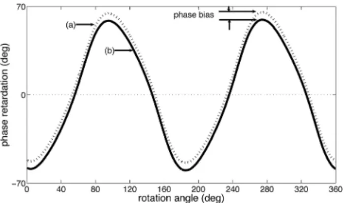
x axis to satisfy the condition of |X共i兲| ⫽ 1 at this stage. Therefore a calibration process is necessary for ensuring a zero phase difference关␦共i兲⫽ 0兴 at the same time for the measurement. A dc phase bias can be obtained by averaging of the measured phase differ-ence versus the rotated angle of the TN-LC within the range of 0°⬍  ⬍ 360° as shown in Fig. 2. Then
X共i兲⫽ 1 of the initial condition of this polarized
inter-ferometric ellipsometer is satisfied. Thus the polar-ization state of output X共o兲emerging from the TN-LC becomes
X共o兲⫽T22 ⫹ T21 T12 ⫹ T11
. (6)
According to Eq. (5) and the relation of
X共o兲⫽
ⱍ
X共o兲ⱍ
exp关
i␦共o兲兴
, (7)␦(0)⫽ tan⫺1
冉再
2 sin␥
2cos 2
冋
sin ␥ 2 sin 2 ⫻ sin 2冉
⫹2冊
⫺ cos ␥2cos 2冉
⫹2
冊册冎冒
冋
cos2␥ 2 ⫺sin 2␥ 2sin 22 ⫺1 2sin 2␥ 2cos 22 ⫻ cos 4冉
⫹2冊册冊
. (8) We can then precisely calculateεand␥ in terms of and␦共o兲by constantly rotating the azimuth angle of the TN-LC and fitting the parameters ofεand␥ with the measured data关, ␦共o兲共兲兴. Generally the rotation of the TN-LC in this experiment produces polariza-tion modulapolariza-tion in this ellipsometer. It shows the same feature as that of the optical photometric method that makes possible phase detection in real time. According to the theory of TN-LC,6the transfermatrix TLCof the TN-LC is expressed by
Then the phase retardation becomes ␦LC共o兲, as
ex-pressed by
␦LC共o兲⫽ tan⫺1
冉再
2冉
⌫兾2
冊
sin冋
cos cos 2␣ ⫺冉
⌽
冊
⫻ sin sin 2␣册冎冒再
cos 2⌽冋
cos2 ⫺冉
⌽ 冊
2 ⫻ sin2册
⫹冉
⌽ 冊
sin 2 sin 2⌽ ⫺冉
⌫兾2 冊
2 ⫻ sin2 cos共4␣ ⫹ 2⌽兲冎冊
, (10) where ␣ is the angle of orientation of the LC mole-cules of the first layer (direction of rubbing in or director angle) relative to the x axis, ⌽ is the twist angle, and ⌫ ⫽ 2共ne ⫺ no兲d兾 indicates the phaseretardation of the TN-LC at ⌽ ⫽ 0. The refractive indices neand noare the extraordinary and ordinary
linear eigenpolarizations of the TN-LC, respectively.
TLC ⫽
冋
T11⬘ T12⬘
T21⬘ T22⬘
册
⫽
冤
cos cos ⌽ ⫹⌽sin sin ⌽ ⫺ i⌫兾2 sin cos共2␣ ⫹ ⌽兲 ⫺cos sin ⌽ ⫹⌽ sin cos ⌽ ⫺ i⌫兾2 sin sin共2␣ ⫹ ⌽兲 cos sin ⌽ ⫺⌽
sin cos ⌽ ⫺ i ⌫兾2
sin sin共2␣ ⫹ ⌽兲 cos cos ⌽ ⫹ ⌽ sin sin ⌽ ⫹ i ⌫兾2 sin cos共2␣ ⫹ ⌽兲
冥
. (9)Fig. 2. Experimental data of phase retardation versus rotation angle of TN-LC by this setup: (a) without phase-bias correction, (b) with phase-bias correction.
Therefore,
⫽
冑
⌽2⫹冉
⌫2
冊
2
, (11)
which is a parameter for characterizing the TN-LC instead of using the original transfer matrix TLC. Lin5
has shown that the equivalent optical axis (or slow axis) of the TN-LC is aligned in the direction of the central line between the directions of rubbing in and rubbing out as shown in Fig. 3 theoretically. Thus the phase retardation␦共o兲as the elliptical phase retarder of Eq. (8) related to the phase retardation as the TN-LC of Eq. (10) can be equivalent to
␦(o)共␥, , 兲 ⫽ ␦LC(o)共⌫, ⌽, ␣兲 (12)
␣ ⫽ ⫺⌽2. (13)
Therefore, ifεand␥ of the TN-LC are given, then ⌽ and ⌫ can be determined by use of the best-fitting algorithm of two curves of ␦共o兲 and ␦LC共o兲 under the
condition of Eq. (13).
3. Experimental Setup and Results
Figure 1 is the optical setup of this phase-sensitive polarized interferometric ellipsometer, in which a 1-mW frequency-stablized linearly polarized He–Ne laser was used. The wavelength was 632.8 nm. The driving frequency of AOM1and AOM2were
1 ⫽ 80.0000 MHz and 2 ⫽ 80.0329, respectively,
which resulted in a beat frequency of ⌬ ⫽ 32.9 kHz in this arrangement. During the measure-ment, the TN-LC was rotated constantly (each rota-tion angle was ⌬ ⫽ 0.2°) by a digitally controlled rotation stage. The phase retardations␦共o兲of P- and
S-polarized optical heterodyne signals were
mea-sured simultaneously. Figure 2 shows the experimen-tal results of phase retardation␦共o兲共兲 versus rotation angle  to the x coordinate, of which a full range of 0° ⬍  ⬍ 360° was scanned. Figure 2(a) shows the measured data for which the phase bias is not
cor-rected. In contrast, Fig. 2(b) calibrates the data of the phase retardation in which phase bias is corrected numerically. In this experiment, the phase bias can be obtained by proper averaging of the measured data from Fig. 2(a), and the result is shown in Fig. 4. To fit ␦共o兲共兲 with the theory of ␦
共o兲共兲, based on a TN-LC
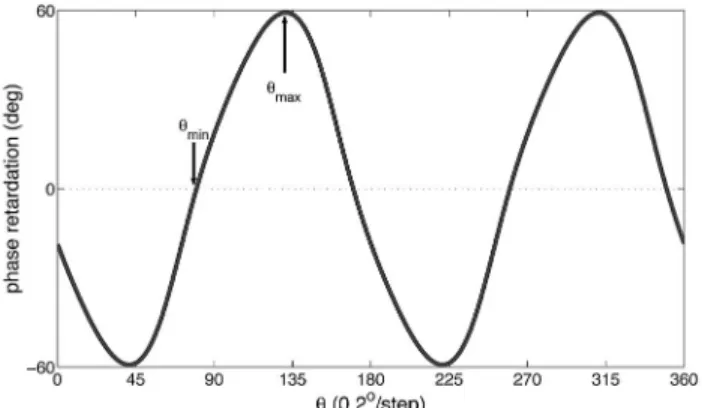
treated as an elliptical phase retarder (see Fig. 5), with ⌬ ⫽ 0.2° per step, ␦共o兲共兲 ⬅ ␦共o兲共, ␥, 兲 is matched numerically by the MATLAB software for this measurement. A bias between and was found numerically according to the following constraints: max⫺ min⫽ max ⫺ min⫽ 51.30°, ␦共o兲共兲max⫽ ␦共o兲共,
␥, 兲max ⫽ 59.238°, and ␦共o兲共兲min ⫽ ␦共o兲共, ␥, 兲min ⫽
0° in the fitting process. As a result, ⫽ ⫺31.741° and ␥ ⫽ 142.810° of the elliptical phase retarder were found numerically. Similarly, the measured phase retardation ␦共o兲共兲 matches ␦LC共o兲共⌽, ⌫, ␣兲 in view of
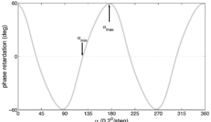
the LC and then follows the same procedures as de-scribed in the elliptical phase retarder previously. Then ⌽ ⫽ 89.804°, ⌫ ⫽ 235.337°, and ⫽ 240.533° were found. Thus the theoretical response of ␦共o兲共, ␥, 兲 versus based on obtained 共, ␥兲 is
shown in Fig. 5. Likewise the theoretical response of ␦LC共o兲共⌽, ⌫, ␣兲 versus ␣ is shown in Fig. 6 accordingly
when共⌽, ⌫兲 is given. Therefore, to match the curves in Figs. 4 – 6 simultaneously such that ␦共o兲 ⫽ ␦共o兲 ⫽ ␦LC共o兲 is satisfied, the angles of the coordinates of
Fig. 3. Schematic diagram of azimuth angle and rubbing angle ␣ of the TN-LC: c indicates the optical axis, i is the direction of rubbing in of the TN-LC, and o is the direction of rubbing out of the
TN-LC. Fig. 4.angle of the TN-LC.Measured phase retardation versus mechanical rotation
Fig. 5. Theoretical calculation of phase retardation versus azi-muth angle of the TN-LC.
s ⫽ 44.6° in Fig. 5 and ␣s ⫽ 89.5° in
Fig. 6 are shifted necessarily, which makes ⌽ ⫽ 2共s⫺ ␣s兲 ⫽ ⫺89.8° in Fig. 3. This is a good
agree-ment with the result of ⌽ ⫽ ⫺89.804° when these three curves are matched simultaneously in Fig. 7.
To correlate the experimental result (Fig. 4) with the theoretical predictions based on an elliptical phase retarder (Fig. 5) and a TN-LC (Fig. 6), the respective correlation coefficients between Figs. 4 and 5 is 0.999918 and between Figs. 4 and 6 is 0.999925. As a result,⌽ ⫽ ⫺89.804° and the param-eter ⌬nd ⫽ 413.67 nm are obtained by this experi-ment. These results agree with the given data (estimated) of the tested TN-LC of ⌽ ⬵ ⫺90° and ⌬nd ⬵ 408 nm in this measurement. From the re-sults, this polarized interferometric ellipsometer en-ables us to characterize TN-LC very precisely both from the consideration of the TN-LC as an elliptical phase retarder and the LC experimentally. To our knowledge, this method provides the highest accu-racy of characterizing a TN-LC device compared with the conventional method.14 –19In addition, this
method also shows the potential capability of
moni-toring the parameters共⌽, ⌫兲 of a TN-LC in real time. It is essential to the performance of TN-LC in the temporal domain.
4. Discussion and Conclusions
This research proposes a phase-sensitive polarized optical heterodyne interferometric ellipsometer in which the tested TN-LC cell is rotated continuously to introduce polarization modulation during the measurement. The ellipsometer combines the fea-tures of optical heterodyne interferometry with op-tical photometry, which makes it possible to present a higher sensitivity of phase detection based on synchronized detection. In the meantime, a capa-bility of real-time measurement is conducted by means of continuous-phase detection. It is similar to the polarization modulation technique in an op-tical photometric method by use of a phase lock-in technique. Therefore, when the optical heterodyne interferometry and optical photometry are incorpo-rated in this novel method, it is possible to improve not only the detection sensitivity but also the dy-namic range of the phase measurement compared with the conventional photometric method. In ad-dition, this polarized interferometric ellipsometer also shows a feature of common-path configuration of P- and S-polarized optical heterodyne signals: A common-phase rejection mode is able to reduce the background-induced phase noise and the laser fre-quency noise significantly. Then an enhancement of the SNR of the detected signal is apparently pro-duced. As a result, for identifying a TN-LC as an elliptical phase retarder, a high accuracy of deter-mining the TN-LC parameters is applicable by this method. This method is also independent of the absorption of the TN-LC device because of phase-sensitive detection in this setup.
Therefore the proposed polarized optical hetero-dyne interferometric ellipsometry enables us to char-acterize a TN-LC very precisely in terms of the phase retardation of P- and S-polarized light waves when the TN-LC is treated identically as an elliptical phase retarder and a LC. The advantages of this polarized interferometric ellipsometry can be summarized by (1) a common-path configuration of the polarized optical heterodyne signals of the interferometer, (2) a synchronized detection of the interferometer result-ing in a high SNR and high sensitivity, (3) a common-phase noise-rejection mode that reduces the back-ground phase noise and laser frequency noise, (4) the feature of optical photometry with polarization mod-ulation that provides a real-time measurement of phase retardation, and (5) a phase-sensitive detection that is independent of the absorption of the TN-LC device.
In conclusion, the parameters of a TN-LC can be precisely determined by this polarized optical inter-ferometric ellipsometer based on the fact that a TN-LC is identical to an elliptical phase retarder. In addition, the equivalent optical axis is verified exper-imentally along the direction of the central line
be-Fig. 6. Theoretical calculation of phase retardation versus rub-bing angle␣ of the TN-LC.
Fig. 7. Phase retardation versus rotation angle of the TN-LC under the conditions of (a) the mechanical rotation of the TN-LC as marker共●兲, (b) the theoretical calculation based on the elliptical phase retarder as marker (--), (c) the theoretical calculation based on a linear TN-LC coincided with (b).
tween the directions of rubbing in and rubbing out of the TN-LC.
We thank Hui-Kang Teng for his kind help with the optical alignment of the interferometry and fruitful discussion on this research. The financial support of this research by the National Science Council of Taiwan, Republic of China, through contract NSC 92-2215-E-010-001, is deeply appreciated.
References
1. C. Chou, Y. C. Huang, and M. Chang, “Polarized common path optical heterodyne interferometer for measuring the elliptical birefringence of a quartz wave plate,” Jpn. J. Appl. Phys. 35, 5526 –5530 (1996).
2. R. M. A. Azzam and N. M. Bashara, Ellipsometry and
Polar-ized Light (North-Holland, 1979), p. 99.
3. H. K. Teng, C. Chou, C. N. Chang, C. W. Lyu, and Y. C. Huang, “Linear birefringence measurement with a differential-phase optical heterodyne polarimeter,” Jpn. J. Appl. Phys. 41, 3140 – 3144 (2002).
4. C. H. Lin, C. Chou, and K. S. Chang, “Real time interferometric ellipsometry with optical heterodyne and phase lock-in tech-niques,” Appl. Opt. 29, 5159 –5162 (1990).
5. B. R. Lin, “TN-LC as an elliptical retarder,” Master’s thesis (Institute of Electro-Optical Engineering, National Chao-Tung University, 2004), p. 19.
6. P. Yeh and C. Gu, Optics of Liquid Crystal Display (Wiley, 1999), pp. 129 –130.
7. Y. C. Huang, M. Chang, and C. Chou, “Effect of elliptical birefringence on the measurement of the phase retardation of a quartz wave plate by an optical heterodyne polarimeter,” J. Opt. Soc. Am. A 14, 1367–1372 (1997).
8. T. Nishiok and T. Kurata, “Novel pretilt angle measure method for twisted-nematic liquid-display cells by apparent retarda-tion measurement,” Jpn. J. Appl. Phys. 40, 6017– 6023 (2001). 9. J. A. Davis, I. Moreno, and P. Tsai, “Polarization eigenstates
for twisted-nematic liquid-crstal display,” Appl. Opt. 37, 937– 945 (1998).
10. I. Moreno, J. A. Davis, K. G. D’Nelly, and D. B. Allison, “Trans-mission and phase measurement for polarization eigenvectors in twisted-nematic liquid crystal spatial light modulators,” Opt. Eng. 37, 3048 –3052 (1998).
11. X. Zhu, Q. Hong, Y. Huang, and S. T. Wu, “Eigenmodes of a reflective twisted-nematic liquid-crystal cell,” J. Appl. Phys.
94, 2868 –2873 (2003).
12. I. Scierski and F. Ratajczyk, “The Jones matrix of the real dicroic elliptic object,” Optik 68, 121–125 (1984).
13. J. A. Davis, J. Nicolas, and A. Márquez, “Phasor analysis of eigenvectors generated in liquid-crystal displays,” Appl. Opt.
22, 4579 – 4584 (2002).
14. Y. Zhou, Z. He, and S. Sato, “A novel method determining the cell thickness and twist angle of a twisted nematic cell by Stokes parameter measurement,” Jpn. J. Appl. Phys. 36, 2760 –2764 (1997).
15. J. A. Davis, D. B. Allison, K. G. D’Nelly, M. L. Wilson, and I. Moreno, “Ambiguities in measuring the physical parameters for twisted-nematic liquid-crystal spatial light modulators,” Opt. Eng. 38, 705–709 (1999).
16. H. Kim and Y. H. Lee, “Unique measurement of the parame-ters of a twisted-nematic liquid-crystal display,” Appl. Opt. 44, 1642–1649 (2005).
17. N. Konforti, E. Marom, and S. T. Wu, “Phase-only modulation with twisted nematic liquid-crystal spatial light modulators,” Opt. Let. 13, 251–253 (1998).
18. S. Valyukh, A. Slobodyanyuk, and V. Sorokin, “Simulation of obliquely incident light propagation through a general twisted nematic liquid crystal cell by the Jones matrix technique,” Semicond. Phys., Quantum Electron. Optoelectron. 3, 258 –263 (2000).
19. R. Giust and J. P. Goedgebuer, “Determination of the twist angle and the retardation properties of twisted nematic liquid crystal television by spectral measurements,” Opt. Eng. 37, 629 – 634 (1998).