國
立
交
通
大
學
資訊科學與工程研究所
碩
士
論
文
電 腦 輔 助 瑜 珈 運 動 學 習 與 自 我 訓 練 系 統
Computer-Assisted Self-Training System for Yoga using Kinects
研 究 生: 何禹禎
指導教授: 李素瑛 教授
陳華總 教授
電腦輔助瑜珈運動學習與自我訓練系統
Computer-Assisted Self-Training System for Yoga using Kinects
研 究 生:何禹禎 Student:Yu-Zhen He
指導教授: 李素瑛、陳華總 Advisor:Suh-Yin Lee, Hua-Tsung Chen
國 立 交 通 大 學
資 訊 科 學 與 工 程 研 究 所
碩 士 論 文
A Thesis
Submitted to Institute of Computer Science and Engineering College of Computer Science
National Chiao Tung University in partial Fulfillment of the Requirements
for the Degree of Master
in
Computer Science
July 2013
Hsinchu, Taiwan, Republic of China
i
電腦輔助瑜珈運動學習與自我訓練系統
研究生:何禹禎
指導老師:李素瑛 教授
陳華總 教授
國立交通大學資訊科學與工程研究所
摘 要
自主練習在各項運動學習上皆扮演了很重要的角色,然而,在沒有教練或指導者的 情況下,不適當的練習姿勢有可能會導致嚴重的運動傷害,所以利用電腦來輔助運動員 自主訓練是近期熱門的研究方向。本論文研究中,我們提出了一個瑜珈自主訓練系統 (YogaST),目的在於輔助使用者以正確的姿勢練習瑜珈,並避免錯誤姿勢所造成之運動 傷害。在此瑜珈運動系統中,我們導入專業的瑜珈訓練知識,同時分析經由正面和側面 兩台 Kinect 得到的資訊,根據不同瑜珈姿勢的要求,輔助使用者修正、調整姿勢,以達 到較佳的自主訓練效果。論文中利用輪廓、拓樸骨架、星狀骨架以及特徵主軸等方式來 展示各個瑜珈姿勢,最終提供視覺化的矯正指示,以利使用者更快速且清楚地調整到正 確姿勢。 關鍵字:運動影片分析、運動訓練、Kinect、自主訓練、瑜珈姿勢分析ii
Computer-Assisted Self-training System for Yoga Using Kinects
Student: Yu-Zhen He Advisor: Prof. Suh-Yin Lee
Prof. Hua-Tsung Chen
Institute of Computer Science and Engineering National Chiao Tung University
Abstract
Self-training plays an important role in sports exercise. However, if not under the instruction of a coach, improper training postures can cause serious harm to muscles and ligaments of the body. Hence, the development of computer-assisted self-training systems for sports exercise is a recently emerging research topic. In this paper, we propose a Yoga self-training system, entitled YogaST, which aims at instructing the user/practitioner to perform the asana (Yoga posture) correctly and preventing injury caused by improper postures. Involving professional Yoga training knowledge, YogaST analyzes the practitioner’s posture from both front and side views using two Kinects with perpendicular viewing directions and assists him/her in rectifying bad postures. The contour, topological skeleton, star skeleton, and feature axes of the human body are extracted as posture representations. Then, YogaST analyzes the practitioner’s posture and presents visualized instruction for posture rectification so that the practitioner can easily understand how to adjust his/her posture.
Keywords— Sports video analysis, sports training, Kinect, self-learning, yoga posture analysis.
iii
Acknowledgement
I would like to thank all those who helped me during the writing this thesis. First of all, I express my sincerely gratitude to my supervisors, Prof Suh-Yin Lee and Prof. Hua-Tsung Chen for their constant encouragement and guidance. I am deeply grateful of their help in the completion of this thesis. Besides, I extend my gratitude to all the members in the Information System Laboratory for their suggestion and instruction, especially Mr. Chien-Li Chou, Mr. Chun-Chieh Hsu, Mr. Ming-Chu Chu and Mr. Kuan-Wei Chen. I also owe my great gratitude to my friends and my roommates who gave me their help and time in listening to me and help me working out my problems during difficult course of the thesis. Last my thanks would go to my beloved family for their loving consideration and great confidence in me in all through these years. This thesis is dedicated to them.
iv
Table of Contents
摘 要 ... i Abstract ... ii Acknowledgement ... iii Table of Contents ... iv List of Figures ... vList of Tables ... vii
Chapter 1. Introduction ... 1
1.1 Motivation and Overview ... 1
1.2 Organization ... 3
Chapter 2. Related Work ... 4
2.1 Microsoft Kinect Sensor and OpenNI ... 4
2.2 Kinect Applications ... 5
2.3 Yoga Systems ... 12
Chapter 3. Computer-Assisted Self-Training System for Yoga using Kinects ... 14
3.1 User Map Capturing and Contour Computation... 16
3.2 Star Skeleton Computation ... 17
3.3 Topological Skeleton Generation ... 19
3.4 Asana Recognition using Star Skeleton ... 21
3.4.1 Feature Definition ... 23
3.4.2 Asana Recognition ... 23
3.5 Descriptor Acquisition ... 25
3.6 Visualized Instruction for Posture Rectification ... 27
Chapter 4. Experimental Results and Discussion ... 43
4.1 Experimental Environment and Data Collection ... 43
4.2 Results of Asana Recognition ... 43
4.3 Performance Evaluation of Visualized Instruction for Posture Rectification ... 45
4.4 Skeleton Extraction usingOpenNI ... 48
v
List of Figures
Fig. 2-1. The Microsoft Kinect sensor. ... 5
Fig. 2-2. OpenNI SDK architecture. ... 5
Fig. 2-3. Framework of the hand gesture recognition system based on FEMD [16]. ... 6
Fig. 2-4. Final results showing hand point, centre of palm and fingertips [17]. ... 6
Fig. 2-5. The Kinect-based wearable haptics: Kinect is in front of the hand. On the screen the rendered scene with hand avatar (left) and the main point of the tracking algorithm (right) [18]. ... 7
Fig. 2-6. Controller-free interactive exploration of medical through Kinect [19]. ... 8
Fig. 2-7. Prototype robot with Kinect sensor and a typical interaction scene [20]. ... 8
Fig. 2-8. The sign language translator user interface [21]. ... 9
Fig. 2-9. Fall detection. (a) Bounding box created. (b) Fall initiated. (c) Inactivity detected. (d) Fall detected [23]. ... 10
Fig. 2-10. Motion parallax without any sensor on a user [25]... 11
Fig. 2-11. Quadrotor helicopter in flight. Kinect sensor is mounted below the centre of the craft, pointing towards the ground [26]. ... 11
Fig. 2-12. CAMBADA (Cooperative Autonomous Mobile robots with Advanced Distributed Architecture) hardware system [27]: (a) The robot platform. (b) Detailed view of the motion system. ... 12
Fig. 2-13. The InterfaceSuit [29]. ... 13
Fig. 2-14. The system interface of YogaExpert [30]. ... 13
Fig. 3-1. Schematic diagram of our proposed YogaST system. ... 15
Fig. 3-2. Illustration of user body map and contour computation: (a) Original RGB frame. (b) User body map. (c) Smoothed body map. ... 16
Fig. 3-3. Process flow of star skeleton computation.. ... 18
Fig. 3-4. Illustration of contour and skeleton computation: (a) Original RGB frame. (b) Distance map. (c) Rough skeleton. (d) Skeleton after denoising. ... 20
Fig. 3-5.Line masks for topological skeleton generation. ... 20
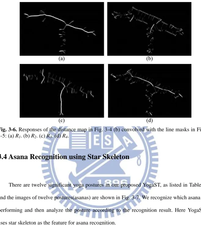
Fig. 3-6. Responses of the distance map in Fig. 3-4 (b) convolved with the line masks in Fig. 3-5: (a) R1. (b) R2. (c) R3. (d) R4. ... 21
Fig. 3-7. Twelve asanas. ... 22
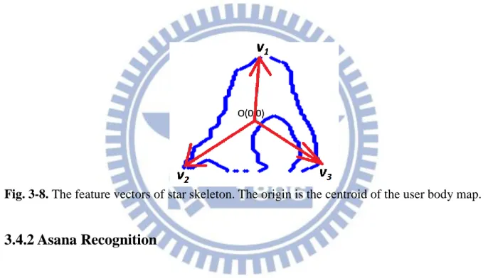
Fig. 3-8. The feature vectors of star skeleton. The origin is the centroid of the user body map. ... 23
Fig. 3-9. Example of misrecognition: Warrior I Pose will be misrecognized as Warrior II Pose, if the mismatched vectors (colored in red) are neglected. ... 25
Fig. 3-10. Processing flow of dominant axis extraction. ... 26
Fig. 3-11. Constraints of the range of for dominant axes Vx and Hx. ... 26
Fig. 3-12. Process flow of corner-based representative point extraction. ... 27
Fig. 3-13. Illustration of contour-based representative point extraction: Phigh,Pleft,Pright ... 27
Fig. 3-14. Original frames and visualized instruction for Tree pose. ... 28
Fig. 3-15. Original frames and visualized instruction for Warrior III pose. ... 29
Fig. 3-16. Illustration of the point O2 extraction: Extract the point O2 by locating the intersection of Vx and Hx. ... 30
Fig. 3-17. Original frames and visualized instruction for Downward-Facing Dog pose. ... 31
Fig. 3-18. Original frames and visualized instruction for Extended Hand-to-Big-Toe pose. ... 32
vi
Fig. 3-20. Illustration of representative point extraction in chair pose. (a) Corner-based
representative points. (b) Representative points extraction in chair pose. ... 33
Fig. 3-21. Original frames and visualized instruction for Full Boat pose. ... 34
Fig. 3-22. Original frames and visualized instruction for Warrior II pose. ... 36
Fig. 3-23. Illustration of separating the corner-based representativepoints. ... 36
Fig. 3-24. Original frames and visualized instruction for Warrior I pose. ... 37
Fig. 3-25. Original frames and visualized instruction for Cobra pose. ... 38
Fig. 3-26. Illustration of separating the corner-based representative points. ... 38
Fig. 3-27. Original frames and visualized instruction for Plank pose. ... 39
Fig. 3-28. Illustration of human body proportion [35]. ... 40
Fig. 3-29. Original frames and visualized instruction for Side Plank pose. ... 41
Fig. 3-30. Original frames and visualized instruction for Lord of the Dance pose. ... 42
Fig. 4-1. Illustration of incorrect recognition: A3 is misrecognized as A11. A2 is misrecognized as A12. (a) Star skeleton of A3 posture performed by the practitioner. (b) Star skeleton of template A11. (c) Star skeleton of template A3. (d) Star skeleton of A2 posture performed by the practitioner. (e) Star skeleton of template A12. (f) Star skeleton of template A2. ... 45
Fig. 4-2. Illustration of incorrect visualized instruction: Noises are generated due to fast movement. ... 46
Fig. 4-3. Illustration of incorrect visualized instruction: The depth difference between the hands and the leg is too large. ... 47
Fig. 4-4.Skeleton of OpenNI. ... 48
vii
List of Tables
Table 1. List of asanas ... 22
Table 2. Confusion matrix of asana recognition ... 44
1
Chapter 1. Introduction
1.1 Motivation and Overview
Sports games have been so exciting and attractive that it fascinates numerous fans, reaching a huge audience base. Sports videos, as important multimedia contents, have been extensively studied due to commercial benefits, entertaining functionalities, and audience requirements.
In the past decade, most of the traditional works in sports video analysis are audience-oriented, aiming at bridging the semantic gap between low-level features and high-level events. Interactive viewing systems based on feature extraction, structure analysis, and semantic inference are developed to provide quick browsing, indexing, and summarization of sports video. Duan et al. [1] utilize a supervised learning scheme to perform a top-down shot classification based on the mid-level representations of motion vector field model, color tracking model, and shot pace model. Zhu et al. [2] rank highlights in broadcast tennis video by affective feature extraction and ranking model construction. Affective features are extracted by recognizing the player actions and analyzing the audience response. The highlight ranking approach combines the player actions with the real-world trajectories and audio keywords to establish the mid-level representation of video content, and support vector regression is employed to construct the nonlinear highlight ranking mode. For baseball highlight extraction and event detection, several approaches based on HMM (Hidden Markov Model) [3]-[4], MEM (Maximum Entropy Model) [5], and BBN (Bayesian Belief Network) [6] with the fusion of various visual and/or audio features are proposed.
2
sports professionals thirst for automatic/semi-automatic systems to assist the coach/ players in better understanding the player actions, tactic patterns, and statistical data, so that they are able to improve their performance and adapt the operational policy during the game. It is keenly expected that the tasks of game annotation, match recording, tactics analysis, and statistics collection, which are time-consuming and labor-intensive, can thus be achieved much efficiently. The trend of sports video analysis goes from semantics to tactics [6]. Chen et al. [7]-[9] track the ball motion in different kinds of sports videos and provide manifold trajectory-based applications, such as pitching evaluation in baseball, shooting location estimation in basketball, and set type recognition in volleyball. To recognize tactical patterns in soccer video, Zhu et al. [10] analyze the temporal-spatial interaction among the ball and the players to construct a tactic representation, aggregate trajectory, based on multiple trajectories. There are also research works focusing on tactic analysis in basketball video [11]-[12], which perform camera calibration to obtain 3D-to-2D transformation, map player trajectories to the real-world court model, and detect the wide-open event or recognize the offensive tactic pattern–screen.
In recent years, the new emerging research topic of computer-assisted self-training in sports exercise has receiving more and more attention. In addition to the regular training courses given by the coach or instructor, most sports players also take time to exercise on their own. However, players may get injured during self-training due to improper postures or training ways. In this thesis, we take Yoga as our research subject and develop a Yoga self-training system, entitled YogaST, for assisting the practitioner in exercising Yoga by himself/herself.
To overcome the limitations of existing works, the proposed YogaST uses two Kinects to extract the body contours from both front and side views, and analyze the posture of the practitioner. Professional Yoga training knowledge is involved, and visualized instruction for
3
posture rectification is presented that the practitioner can easily understand how to adjust his/her posture, preventing injury caused by improper postures.
1.2 Organization
The rest of this thesis is organized as follows. In Chapter 2, we give some background knowledge, including the introduction of Microsoft Kinect sensor and OpenNI, and existing research works about Yoga training. In Chapter 3, the framework of our proposed YogaST system is elaborated in detail. The processing steps of asana recognition, contour and skeleton computation, and dominant axis and representative point extraction, as well as the visualized instruction for posture rectification are elaborated in Chapter 3. Subsequently, system evaluation is provided in Chapter 4. Finally, Chapter 5 gives the conclusion of this thesis.
4
Chapter 2. Related Work
In Chapter 2, we introduce the background knowledge and the related works. In Section 2.1, we introduce the 3D sensor device Kinect and the middleware OpenNI used in YogaST. In Section 2.2, we introduce some applications of Kinect and in Section 2.3 we introduce the existed yoga systems.
2.1 Microsoft Kinect Sensor and OpenNI
As shown in Fig. 2-1, Kinect [13] is a new game controller technology introduced by Microsoft in November, 2010. Kinect includes a RGB color camera, a depth sensor, and a muti-array microphone. The depth sensor consists of an infrared laser projector combined with a monochrome CMOS sensor, and allows Kinect to process 3D scenes in any ambient light condition. Kinect claimed the Guinness World Record of being the “fastest selling consumer electronics device” after selling a total of 8 million units in its 60 days [14]. Because of its low price and great convenience, as the launch of Kinect, lots of developers and scholars use the device not only on the games but also on the other applications. In Section 2.2, we introduce some applications of Kinect.
In order to develop Kinect-based system, the middleware that facilitates access and use of the devices is required. One of the important development tools for Kinect is Open Natural Interaction (OpenNI) [15], as shown in Fig. 2-2. OpenNI is an open source tool provided by PrimeSense, whose depth sensing reference design Kinect is based on. The OpenNI framework provides a set of open source APIs. The APIs provide support for voice command recognition, hand gesture and body motion tracking. With OpenNI, the developer can access
5
the depth information of a human subject, estimate and track its articulate pose.
Fig. 2-1. The Microsoft Kinect sensor.
Fig. 2-2. OpenNI SDK architecture.
2.2 Kinect Applications
According to the capability of Kinect to produce depth and RGB streams at a price much lower than traditional range sensors, the 3D sensor is transforming not only computer gaming but also many other applications.
6
Ren et al. [16], Raheja et al. [17] and Frati et al. [18] all use Kinect for hand tracking, finger tracking, and gesture recognition. Ren et al. use depth information and a threshold to segment the hands and propose a dissimilarity distance metric─Finger Earth Mover’s Distance (FEMD) for gesture recognition, as shown in Fig. 2-3. Raheja et al. locate the hands by OpenNI library and use distance transform and depth information to find the center and the fingertips of hands, as shown in Fig. 2-4. Frati et al. use Kinect as a sensor of wearable haptics, as shown in Fig. 2-5. The positions of the fingertips are measured by the hand tracker designed and optimized for Kinect, and the rendering algorithm computes the contact forces for wearable haptic display.
Fig. 2-3. Framework of the hand gesture recognition system based on FEMD [16].
7
Fig. 2-5. The Kinect-based wearable haptics: Kinect is in front of the hand. On the screen the
rendered scene with hand avatar (left) and the main point of the tracking algorithm (right) [18].
However, Kinect-based gesture recognition systems have been integrated in some applications. Gallo et al. apply Kinect-based gesture recognition systems on contact-free visual data interaction in operating room [19]. As shown in Fig. 2-6, there is a system using Kinect as the only input device and allowing users to interact at a distance through hand and arm gestures. Van den Bergh et al. use Kinect in human-robot interaction [20], as shown in Fig. 2-7. The system implements a Harrlet-based hand gesture recognition to detect hand gestures while extracting the 3D point direction and is integrated on an interactive robot. Li et al. design a sign-translation platform for hearing-impaired people [21], as shown in Fig. 2-8. The system captures the 3D data of the joints of the user by Kinect, analyzes and matches these data to a library of pre-recorded signs and translates the matched sign to a word or phrase.
8
Fig. 2-6. Controller-free interactive exploration of medical through Kinect [19].
9
Fig. 2-8. The sign language translator user interface [21].
Kinect is also used in human behavior analysis. Yu et al. [22] analyze children tantrum behavior according to medical knowledge, questionnaire based attitudes investigation and Kinect based behavior analysis algorithm. Mastorakis et al. [23] design a real time fall detection system, as shown in Fig. 2-9. The key of this system is measuring the velocity based on the contraction or expansion of the width, height and depth of the 3D bounding box. Ganesan et al. [24] use Kinect to encourage older adults to exercise. The data gathering includes an interview with an expert in aging and physical therapy and a focus group with older adults on the topics of exercise and technology. Based on these data, the early prototype game has been implemented for the Microsoft Kinect.
10
Fig. 2-9. Fall detection. (a) Bounding box created. (b) Fall initiated. (c) Inactivity detected. (d)
Fall detected [23].
Additionally, Hirose et al. [25] apply Kinect on virtual reality for museum exhibit. They construct the Digital Display Case system that use Kinect to detect and track user’s face and calculate images on displays to enable users to appreciate virtual exhibits as if they are really in the virtual case, as shown in Fig. 2-10. Stower et al. [26] calibrate the Kinect depth and an image sensor, and then use the depth map to control the altitude of a quadrotor helicopter, as shown in Fig. 2-11. Cunha et al. [27] use Kinect to assist indoor robot localization and navigation, as shown in Fig. 2-12. The robot makes use of a metric map of the environment’s walls, uses the depth information of the Kinect camera to detect the walls, and finally localize itself in the environment.
11
Fig. 2-10. Motion parallax without any sensor on a user [25].
Fig. 2-11. Quadrotor helicopter in flight. Kinect sensor is mounted below the centre of the
12
Fig. 2-12. CAMBADA (Cooperative Autonomous Mobile robots with Advanced Distributed
Architecture) hardware system [27]: (a) The robot platform. (b) Detailed view of the motion system.
2.3 Yoga Systems
As an ancient Indian art, Yoga exercise not only promotes physical health but also helps to purge the body, mind, and soul. Therefore, Yoga is becoming more and more popular. Patil et al. [28] describe the project “Yoga tutor” which uses SURF (Speeded Up Robust Features) to detect and visualize the postural difference between a practitioner and an expert. However, only the contour information captured from one viewing-direction seems unable to describe and compare the postures appropriately. Luo et al. [29] propose a Yoga training system based on motion replication technique (MoRep). The InterfaceSuit, comprising Inertial Measurement Units (IMUs) and tactors, as shown in Fig. 2-13, is able to capture the precise body motions, but it does influence the practitioner’s exercising. Wu et al. [30] develop a Yoga expert system, which instructs training technique based on images and text, as shown in Fig. 2-14. However, the practitioner’s posture is not analyzed so that he/she is unable to know whether an asana is performed correctly or not.
13
Fig. 2-13. The InterfaceSuit [29].
14
Chapter 3. Computer-Assisted Self-Training System for
Yoga using Kinects
The schematic diagram of our proposed system—YogaST is illustrated in Fig. 3-1. Two Kinects with perpendicular viewing directions are located at a distance of more than 200 cm away from the practitioner to capture the body maps of both front and side views, as shown in Fig. 3-1(a). Yoga comprises various asanas (the word ‘asana’ comes from Sanskrit, denoting a static physical posture), and each asana has its respective postural emphasis. For example, the asana in Fig. 3-1, called Plank Pose, tones the abdominal muscles while strengthening the arms and spine. To recognize what asana the practitioner is performing, YogaST first computes the star skeleton [31] from the body map, as shown in Fig. 3-1(b). The star skeletons of templates for asanas are pre-built, and a distance function is applied for template matching for asana recognition. In addition to the feature of contour, we also require a feature to describe the body structure of the practitioner. YogaST computes the topological skeletons from the body maps, as shown in Fig. 3-1(d). Then, YogaST extracts dominant axes and representative points according to the training emphasis of each asana, as shown in Fig. 3-1(e) and (f). After analyzing the practitioner’s posture, YogaST, which involves professional Yoga training knowledge, presents visualized instruction for posture rectification, as shown in Fig. 3-1(g). In the following sub-sections, each processing step will be elaborated in detail.
15
16
3.1 User Map Capturing and Contour Computation
For feature extraction, YogaST first captures the binary body maps (using OpenNI library [15]) of front and side views from two Kinects with perpendicular viewing directions. For each body map, YogaST performs the following processing steps, as illustrated in Fig. 3-2, wherein a side-view map is taken for example, and Figs. 3-2(a) and (b) are the original RGB frame and the captured body map, respectively. Fig. 3-2(c) shows the smoothed body map after the “open” operation. Then, the contour can be extracted (c.f. OpenCV [32]), as shown as Fig. 3-2(d).
Fig. 3-2. Illustration of user body map and contour computation: (a) Original RGB frame. (b)
17
3.2 Star Skeleton Computation
The concept of star skeleton is to connect from centroid to gross extremities of a body contour. To derive the gross extremities of body contour, the distance from the centroid to each contour point is computed in a clockwise order. Then, we smooth the distance signal by Gaussian smoothing filter and locate extremities at the representative local maxima of the distance signal, as shown as Fig. 3-3. Note that we modify the original star skeleton algorithm [31] via calculating the centroid of the whole body, which is more robust to posture change, instead of the centroid of the body contour. The algorithm of star skeleton computation is presented as Algorithm 1.
Algorithm 1:
(Star Skeleton Computation)Input:
Human body mapOutput:
A skeleton in star fashion1. Define the centroid of the human body map
(3-1) (3-2)
where N is the number of body pixels .
18
(3-3)
3. Smooth the distance signal to for the noise reduction by Gaussian smoothing filter, as shown in Fig. 3-3.
4. Take the local maxima of the signal as the extreme points and construct the star skeleton by connecting extreme points to the centroid . Local maxima are detected by finding zero-crossing of the difference function.
(3-4)
19
3.3 Topological Skeleton Generation
The topological skeleton is a thin version of a shape that is equidistant to its boundaries. The processing steps of contour and skeleton computation are illustrated in Fig. 3-4. First, we apply the distance transform on the user body map to produce a distance map, as shown in Fig. 3-4 (b). The distance transform is an operator normally only applied to binary images. The result of the transform is a graylevel image that shows the distance to the closest boundary from each point. Then the skeleton map is generated in the way that four line masks, mask1,
mask2, mask3 and mask4, as given in Fig. 3-5, are run individually through the distance map.
Let R1, R2, R3, and R4 denote the responses of the masks, as shown in Fig. 3-6. At a certain
point in the distance map, let Rmax = max(|R1|, |R2|, |R3|, |R4|), and if Rmax is greater than a
threshold, the pixel value at the corresponding point in the skeleton map to be produced is set to 1; otherwise, it is set to 0. One can see that the skeleton map presented in Fig. 3-4(c) can describe the posture appropriately. Finally, we refine the rough skeleton map by extracting the parts of the main connected components and eliminating the thin branches close to the contour, as shown in Fig. 3-4(d).
20
Fig. 3-4. Illustration of contour and skeleton computation: (a) Original RGB frame. (b)
Distance map. (c) Rough skeleton. (d) Skeleton after denoising.
21
Fig. 3-6. Responses of the distance map in Fig. 3-4 (b) convolved with the line masks in Fig.
3-5: (a) R1. (b) R2. (c) R3. (d) R4.
3.4 Asana Recognition using Star Skeleton
There are twelve significant yoga postures in our proposed YogaST, as listed in Table1, and the images of twelve postures(asanas) are shown in Fig. 3-7. We recognize which asana is performing and then analyze the posture according to the recognition result. Here YogaST uses star skeleton as the feature for asana recognition.
Yoga comprises various asanas, each of which denotes a static physical posture. Thus, we can pre-build templates for different asanas by extracting the star skeleton of the standard static postures performed by a Yoga expert, as shown in Fig. 3-1(c). Then, YogaST compares the practitioner’s posture with the pre star skeleton of the user with each asana template to recognize what asana the user is performing.
22
Table 1. List of asanas
A1 Tree A7 Warrior II A2 Warrior III A8 Warrior I A3 Downward-Facing Dog A9 Cobra A4 Extended Hand-to-Big-Toe A10 Plank A5 Chair A11 Side Plank
A6 Full Boat A12 Lord of the Dance
23
3.4.1 Feature Definition
After extracting star skeleton, we define the feature as a set of vectors from the centroid to shape extremities, as shown in Fig. 3-8. Since the value of the feature vector varies with the human size and shape, normalization is required to get relative distribution of the feature vector. We perform normalization via dividing the vectors by the maximum length of the vectors in the star skeleton feature. In Fig. 3-8, suppose v2 with the maxima length, the vectors
v1, v2 and v3 will be normalized by the length of v2.
Fig. 3-8. The feature vectors of star skeleton. The origin is the centroid of the user body map.
3.4.2 Asana Recognition
YogaST compares star skeleton feature of the user V with each star skeleton feature of template T. The distance of V and T is evaluated by the following equation:
(3-5)
where
24
, n is the number of vectors in the set V. , m is the number of vectors in the set T.
However, here comes a problem. For example, Warrior I Pose may be misrecognized as Warrior II Pose, as shown in Fig. 3-9, because only the sum of the distances between the matched skeleton vectors is considered but the mismatched vectors are neglect. To overcome the problem, we should incorporate some penalty mechanism for the mismatched vectors. Since the star feature vector with larger length is more important and the extremities of the star skeleton are mainly from the head, two hands, and two legs, we take into account the longest first five vectors of each template skeleton. Then, a penalty value will be added to the distance function for each mismatched vector. The distance function DP is revised by adding the penalty term p and the asana can be recognized by choosing the template with the minimal , as follows.
(3-7)
(3-8)
25
Fig. 3-9. Example of misrecognition: Warrior I Pose will be misrecognized as Warrior II Pose,
if the mismatched vectors (colored in red) are neglected.
3.5 Descriptor Acquisition
Star skeleton gives much information of the user contour extremes while topological skeleton facilitates the acquisition of the whole body structure of the user. With the star skeleton and topological skeleton computed, now we intend to extract the following dominant axes and representative points for subsequent posture analysis
Dominant axes: To present the general distribution of the body and limbs, we extract the
feature lines of the practitioner body by applying Hough transform to the topological skeleton map, as shown in Fig. 3-10. In order to obtain the dominant axes of interest, we define constraints on the range of , as shown in Fig. 3-11. The line which has the maximal value in the range of [/8, /8] is extracted as vertical axis Vx, and the line with [/4, 3/4] is extracted as horizontal axis Hx.
26
Fig. 3-10. Processing flow of dominant axis extraction.
Fig. 3-11. Constraints of the range of for dominant axes Vx and Hx.
Corner-based representative points: In addition to the dominant axes, representative
points are also indispensable to describe the user’s posture in detail. Thus, we extract representative points by detecting the corners in the topological skeleton. We apply Harris corner detection [33] and build a corner map, as shown in Fig. 3-12. In the upcoming processing of posture analysis, different representative points are chosen from these detected corners according to different asanas.
27
Fig. 3-12. Process flow of corner-based representative point extraction.
Contour-based representative points: Some representative points are extracted from
the body contour. As illustrated in Fig. 3-13, the highest point (termed Phigh) of the star
skeleton, the farthest points in the left and right halves of the star skeleton (termed Pleft and
Pright, respectively) are extracted as contour-based representative points.
Fig. 3-13. Illustration of contour-based representative point extraction: Phigh,Pleft,Pright
3.6 Visualized Instruction for Posture Rectification
Our proposed YogaST system is capable of assisting the practitioner in practicing twelve asanas, including (1) Tree, (2) Warrior III, (3) Downward-Facing Dog, (4) Extended Hand-to-Big-Toe, (5) Chair, (6) Full Boat, (7) Warrior II, (8) Warrior I, (9) Cobra, (10) Plank, (11) Side Plank, and (12) Lord of the Dance, as given in Table 1. Since each asana has its own postural emphasis (please refer to [34]), different dominant axes and representative points are
28
used to describe the postures of different asanas and provide visualized instruction for posture rectification. In the following, we will elaborate each asana in detail
(1) Tree is a basic pose in Yoga, as shown in Fig. 3-14, which emphasizes that the body
should be upright and maintains balance. As shown in Fig. 3-14(c) and (d), Phigh and Plow are
the highest and lowest points in contour-based representative points, and O1 is the centroid of
the user body. Then, we connect O1 to Phigh and Plow, termed axes L1 and L2, respectively.
Thus the axes L1 and L2 can reveal whether the practitioner is tilting in the front or side view,
as well as display the tilt angles.
Fig. 3-14. Original frames and visualized instruction for Tree pose.
(2) Warrior III, as shown in Fig. 3-15, is kind of a difficult pose that the arms, torso,
and raised leg should be positioned relatively parallel to the floor, with balance maintained by the other leg. As shown in Fig 3-15(c), L1 and L2 are extracted in the same way as Tree pose
29
and used in front view to reveal if the practitioner is tilting. In the side view, we extract the point O2 by locating the intersection of Vx and Hx, as shown in Fig. 3-16. Other points are
obtained from the contour-based representative points: Pleft for the leftmost point, Pright for the
rightmost point, and Plow for the lowest point. Then, we connect O2 to Pleft, Pright and Plow for
deriving L3, L4, and L5. As show in Fig. 3-15(d), L3 and L4 are used in the side view to
measure whether the arms, torso, and raised leg are parallel to the floor. The angle between L3
and a horizontal line suggests that the arms and torso can be a little lower, while the angle ө between L4 and a horizontal line is displayed, reminding the practitioner to raise the leg
higher.
30
Fig. 3-16. Illustration of the point O2 extraction: Extract the point O2 by locating the
intersection of Vx and Hx.
(3) Downward-Facing Dog is an essential pose in the majority of yoga classes that the
hands are put on the floor, and the back should be lengthened along its entire length so that the arms and back form one line, as demonstrated in Fig. 3-17. Besides, legs should be stretched and straightened. In the both views we extract the leftmost, the rightmost and highest point from the contour-based representative points, named Pleft, Pright and Phigh. As
shown in Fig. 3-17(c), we connect the centroid of the body map to Phigh, Pleft, and Pright,
termed L1, L6, and L7, respectively. L1 in the front view can disclose the left or right tilt of the
body. As shown in Fig. 3-17(d), we connect Phigh to Pleft and Pright, termed L8 and L9, so as to
indicate whether the arms and back (colored red) form one line and whether the legs (colored green) are straightened.
31
Fig. 3-17. Original frames and visualized instruction for Downward-Facing Dog pose.
(4) Extended Hand-to-Big-Toe is a pose that helps in stretching the hamstrings so the
practitioner performing this pose have to stand straight, slowly swing the foot to the front, and maintain the balance, as shown in Fig. 3-18. Here, the raised-leg foot is raised as higher as possible. As demonstrated in Fig. 3-18(c), we show the same visualized instruction as Tree pose. In the side view, we locate O2 in the same method as Warrior III pose by extracting the
intersection of Vx and Hx and connect O2 to the derived contour-based representative points
Phigh, Plow, and Pleft. As show in Fig. 3-18(d), the axes L1 and L2 assist us to reveal whether the
32
Fig. 3-18. Original frames and visualized instruction for Extended Hand-to-Big-Toe pose.
(5) Chair, as shown in Fig. 3-19, is a pose that the practitioner sits back with raising
his/her arm overhead. The practitioner should keep the natural curve of his/her lower back, finding balance between drawing in your lower belly while sending your tailbone towards the earth. Because the pose is just like sitting on a chair, the thighs should be relatively parallel to the floor. As shown in Fig. 3-19(c), L1 and L2 are extracted for analyzing the front view. On
the other side, we attempt to obtain the key joints from the corner-based representative points. As illustrated in Fig. 3-20, we sort these points according to their y-coordinates, termed as P1,
P2, … Pn, and we eliminate a point Pi if the angle of and is larger than a
threshold. In general cases, we extract two points P4 and P5, also named Pjoint1 and Pjoint2 in
Fig. 3-19(d). In addition, we locate the lowest point of the contour-based representative points, Plow and the highest point Phigh of the contour-based representative points. According to these
33
extracted points, we obtained L11, L12, and L13, as illustrated in Fig.3-19(d). The axis L13 is
appropriate to reveal whether the thighs of practitioner are relatively parallel to the floor.
Fig. 3-19. Original frames and visualized instruction for Chair pose.
Fig. 3-20. Illustration of representative point extraction in chair pose. (a) Corner-based
34
(6) Full Boat is a great yoga pose for strengthening the abdominal organ. As presented in
Fig. 3-21, the practitioner sits on the floor and lifts his/her feet off the floor. Then, the thighs are angled about 60 degrees relative to the floor. As show in Fig. 3-21(c), in the front view, the analysis is the same as Tree pose. In the side view, first we extract the leftmost and the rightmost point from the points of the corner map, termed Pjoint_left and Pjoint_right. Second, we
obtain the center O1 and the lowest point of contour-based points Plow. Third, we locate O3 at
(x-coordinate of O1, y-coordinate of Plow) and connect O3 with Pjoint_left and Pjoint_right, termed
L14 and L15, as shown in Fig. 3.21(d). Finally, L14 assists the practitioner to adjust his/her feet
lower or higher.
Fig. 3-21. Original frames and visualized instruction for Full Boat pose.
(7) Warrior II is a beautiful pose that inspires grace and strength, as presented in Fig.
35
perpendicular to the floor. Finally, he/she bends the front knee over the ankle so the shin is parallel to the floor and the front thigh parallel to the floor. As shown in Fig. 3-22(c), we apply the same axes L1 and L2 extracted in the same method as Tree pose in the front view. In
the side view, we extract the two leftmost (rightmost) points from the contour-based representative points. Then we locate Pleft_high (Pright_high) as the higher point and Pleft_low
(Pright_low) as the lower point. In order to confirm the calf is perpendicular to the floor and the
thigh is parallel to the floor, we locate the Pjoint4 and Pjoint3. In order to extract the key joints of
the leg of the practitioner, we take the point O1 as the origin and separate the body map into
four quadrants, termed LH, LL, RH, and RL, as shown in Fig. 3-23, and then we sort the points in LL in descending order and the points in RL in increasing order of their y-coordinates and we have the sequential points of the two legs. In the normal case we derive the Pjoint3 as the highest point of LL and the Pjoint4 as the second point of LL. In the upper part
of the body, we locate the point that is nearest to the middle point of Phigh and Pjoint3, termed
Pjoint5 and connect Pjoint5 with Pleft_high and Pright_high, termed L16 and L17. We connect Pjoint3 with
Phigh, termed L18. In the lower part of the body, we connect the Pjoint4 with Pleft_low and Pjoint3,
termed L19 and L20. As shown in Fig. 3-22(d), the axes L16 and L17 assist us to verify whether
the arms of practitioner parallel to the floor, the axis L18 assist us to verify if the practitioner is
36
Fig. 3-22. Original frames and visualized instruction for Warrior II pose.
Fig. 3-23. Illustration of separating the corner-based representativepoints.
(8) Warrior I is a pose similar to Warrior II, as shown in Fig. 3-24. The lower part of the
body is the same as Warrior I but the arms of the practitioner are raised to the side of shoulder height and parallel to the floor. In the front view, we extract Phigh_mid as the middle point of
two highest contour-based representative points and connect O1 to Phigh_mid and Plow, termed
37
method as the Warrior I pose. Then we display instruction according to these axes as shown in 3-24(d).
Fig. 3-24. Original frames and visualized instruction for Warrior I pose.
(9) Cobra is a great exercise for people with lower back aches, as shown in Fig. 3-25.
The practitioner lies face down on the floor with the palms flat, placed beneath the shoulders. Then, the practitioner pushes his/her upper body off the floor and straightens the arms as much as is comfortable while keeping the hips, legs, and feet planted on the floor. Note that do not overdo the back bend, otherwise it may cause injury. In the front view, we apply the same method as Downward-Facing Dog pose, as shown in Fig. 3-25(c). In the side view, we aim to obtain the curve of the main part of body. In this asana we take the point O1 as the
center and separate the user body map into 2 parts, termed LP and RP, as shown in Fig. 3-26. Then we sort the corner-based representative points in LP in increasing order of their
38
y-coordinates and sort the ones in RP in increasing order of their x-coordinates. In order to reveal the curve clearly, we eliminate the points near the Pleft and the point Pi that the angle of
and is larger than a threshold. As shown in Fig. 3-25(d), we keep P joint_high,
Pjoint5, Pjoint6, and Pjoint_right, and connect them according to their position. Here, we obtain L21,
L22, and L23, and use them to display whether the practitioner is overdoing the back bend.
Fig. 3-25. Original frames and visualized instruction for Cobra pose.
Fig. 3-26. Illustration of separating the corner-based representative points.
39
strengthening the arms and spine. As shown in Fig. 3-27, the practitioner puts the hands on the floor and brings the body into one straight line, from shoulder to heels.In the front view, we apply the same method as Downward-Facing Dog pose, as shown in Fig. 3-24(c). In the other view, we extract the point which is highest point of the points that their x-coordinates are close to the x-coordinate of Pleft_low from the corner-based representative points, termed
Pjoint7. According to the adult body proportion [35], as shown in Fig. 3-28, the ratio of the
distance from the shoulder to the hip to the distance from the hip to the feet is about 2:4. We define Pjoint7 as the shoulder and Pright as the feet and then we obtain the Pjoint8, of which the
location is closest to the ideal location of the hip from the corner-based representative points. As shown in Fig. 3-27(d), we connect Pjoint8 to Pjoint7 and Pright, termed L24 and L25, and use
these two axes to infer if the body of the practitioner is presented in a straight line.
40
Fig. 3-28. Illustration of human body proportion [35].
(11) Side plank challenges the stability and improves core strength by working the
muscles along the side of your body. As shown in Fig. 3-29, the practitioner starts the pose by lying on the side with legs straight and feet stacked. Then, the practitioner straightens the bottom arm, raises the hips until the boy forms a straight line from the shoulder to the ankles and extends the other hand toward the ceiling.In the front view, we apply the same method as
Tree pose, as shown in Fig. 3-29(c). In the side view, first, we extract O2 in the same way as
Warrior III pose and obtain the point nearest to O2 in the corner-based representative points,
termed Pjoint9. Second, we define Pjoint9 as the shoulder and apply the same method as Plank
pose to attain the hip point, termed Pjoint8 in Fig. 3-29(d). Third, we connect the Pjoint8 to Pjoint9
and Pright, termed L28 and L25. In the part of the arms, we connect Pjoint9 to Phigh and Plow,
termed L26 and L27. Finally, we use axes L26 and L27 to reveal if the practitioner's arms are put
in a straight line and use L28 and L25 to infer if the body of the practitioner is presented in a
41
Fig. 3-29. Original frames and visualized instruction for Side Plank pose.
(12) Lord of the dance requires the pose to be done gracefully, almost like a dance, as
shown in Fig. 3-30. The first is to reach back with the left (right) hand and grasp the outside of your left (right) foot or ankle. Then, the practitioner begins to lift the left (right) foot up, away from the floor, and back, away from his/her torso with stretching the right (left) arm forward, in front of your torso. As shown in Fig. 3-30(c), we apply the same way as Tree pose in the front view. In the side view, the practitioner has to keep the balance and try hard to raise his back foot as higher as possible so we extract Pright_high as the back foot. Additional we
locate the point Pjoint10 which is closest to Pjoint_high in the corner-based representative points
and connect Pjoint10 to Pright_high, termed L28. As shown in Fig 3-30(d), L28 assist in revealing if
42
43
Chapter 4. Experimental Results and Discussion
In this chapter, we explain the experiments of asana recognition as well as the performance evaluation of visualized instruction for posture rectification, and discuss the results. The experimental environment is described in Section 4.1. The results of asana recognition are presented in Section 4.2, and Section 4.3 gives the performance evaluation of visualized instruction for posture rectification. Finally, the discussion on OpenNI skeleton is also presented in Section 4.4.
4.1 Experimental Environment and Data Collection
The proposed YogaST system is implemented in C++ with OpenNI 1.5.4.0 [15] and OpenCV (Open Source Computer Vision) 2.3.1[32] libraries, and run on an Acer notebook (Intel Core i5 CPU M430 @2.27GHz, 4GB RAM, Windows 7 64-bit OS). Twelve typical asanas are selected in our system, as listed in Table 1. The experiments are conducted in such a way that five practitioners perform each of the twelve asanas five times. Then a Yoga expert is asked to judge whether the visualized instruction generated by YogaST in each frame is appropriate or not through a simple user-friendly interface.
4.2 Results of Asana Recognition
YogaST uses an observation window of forty frames for each video clip and recognizes the human posture in each frame in the window. Then, majority voting is applied to decide what asana the practitioner is performing in the video clip. The confusion matrix of asana
44
recognition is presented in Table 2, wherein the left column indicates the ground truth of asanas, and the top row indicates the recognition results. For brevity, in this section all asanas are abbreviated to its code name Ai (i = 1~12), as given in Table 1. The elements on the diagonal of the confusion matrix represent the numbers of correctly recognized asanas. Since these asanas are quite different from each other in appearance, almost all asanas can be correctly recognized, except for two error cases, as given in Fig. 4-1. Overall, the proposed YogaST can achieve a quite high accuracy of 99.33% (298/300) in asana recognition. As shown in Fig. 4-1, the error cases in asana recognition is due to the reason that the posture performed by the practitioner is too far from the template so the star skeleton feature is more similar to the other asana.
Table 2. Confusion matrix of asana recognition
Ground truth
Recognition results
A1 A2 A3 A4 A5 A6 A7 A8 A9 A10 A11 A12 A1 25 0 0 0 0 0 0 0 0 0 0 0 A2 0 24 0 0 0 0 0 0 0 0 0 1 A3 0 0 24 0 0 0 0 0 0 0 1 0 A4 0 0 0 25 0 0 0 0 0 0 0 0 A5 0 0 0 0 25 0 0 0 0 0 0 0 A6 0 0 0 0 0 25 0 0 0 0 0 0 A7 0 0 0 0 0 0 25 0 0 0 0 0 A8 0 0 0 0 0 0 0 25 0 0 0 0 A9 0 0 0 0 0 0 0 0 25 0 0 0 A10 0 0 0 0 0 0 0 0 0 25 0 0 A11 0 0 0 0 0 0 0 0 0 0 25 0 A12 0 0 0 0 0 0 0 0 0 0 0 25
45
Fig. 4-1. Illustration of incorrect recognition: A3 is misrecognized as A11. A2 is
misrecognized as A12. (a) Star skeleton of A3 posture performed by the practitioner. (b) Star skeleton of template A11. (c) Star skeleton of template A3. (d) Star skeleton of A2 posture performed by the practitioner. (e) Star skeleton of template A12. (f) Star skeleton of template A2.
4.3 Performance Evaluation of Visualized Instruction for Posture
Rectification
The performance evaluation of visualized instruction for posture rectification is presented in Table 3, wherein the first columns indicate the front and side views (termed ‘F’ and ‘S’) of the twelve asanas. In the top row, “#appropriate” and “#inappropriate” indicate the numbers of appropriate and inappropriate visualized instruction, respectively, and the accuracy is computed by:
46
The results in Table 3 show that in the majority of frames, the visualized instruction can represent the practitioner’s posture appropriately when he/she is performing an asana. The accuracy of the Warrior III-A3 pose is a little lower. The overall accuracy of about 94.36% is sufficient to instruct the practitioner to rectify his/her posture informatively. Based on observation, we discover that the errors in visualized instruction are mainly caused by incorrect segmentation of the user body map. As shown in Fig. 4-2, visualized instruction cannot represent the raised leg satisfactorily due to the incorrect segmentation of the foot. As shown in Fig. 4-3, there is also the case that the depth difference between the hands and the leg is too large, so that the whole body cannot be segment correctly. We will take this situation into consideration and enhance the segmentation in our future work so as to overcome such limitation.
Fig. 4-2. Illustration of incorrect visualized instruction: Noises are generated due to fast
47
Fig. 4-3. Illustration of incorrect visualized instruction: The depth difference between the
hands and the leg is too large.
Table 3. Results of visualized instruction
Asana (view) #appropriate #inappropriate Accuracy
A1 (F) 3706 5 99.87 A1 (S) 3581 130 96.50 A2 (F) 2873 70 97.62 A2 (S) 2918 25 99.15 A3 (F) 2536 791 76.22 A3 (S) 2974 353 89.39 A4 (F) 1961 53 97.37 A4 (S) 1714 300 85.10 A5 (F) 1852 72 92.20 A5 (S) 1750 147 92.25 A6 (F) 1547 90 94.50 A6 (S) 1584 53 96.76 A7 (F) 2826 14 99.51 A7 (S) 2638 202 92.89 A8 (F) 2589 46 98.25 A8 (S) 2502 133 94.95 A9 (F) 2249 177 92.70 A9 (S) 2294 132 94.56 A10 (F) 2169 68 96.95 A10 (S) 2096 132 94.08 A11 (F) 1509 24 98.43 A11 (S) 1407 126 91.78 A12 (F) 2023 10 99.50 A12 (S) 1888 145 92.87 Total 55186 3298 94.36
48
4.4 Skeleton Extraction usingOpenNI
Here we discuss the skeleton generated by OpenNI library[17]. As shown in Fig. 4-4, OpenNI skeleton consists of 15 joints: head, neck, torso center, right shoulder, left shoulder, right elbow, left elbow, right hand, left hand, right hip, left hip, right knee, left knee, right foot and left foot.
Fig. 4-4.Skeleton of OpenNI.
OpenNI skeleton works well in the situation that the user’s body and limbs can be separated obviously. However, OpenNI skeleton is not applicable to our yoga system due to the problem that some parts of the body may be occluded by the practitioner him/herself when performing most of Yoga asanas, as shown in Fig. 4-5. For example, the posture of the practitioner in Fig. 4-5(g), who is performing Warrior II, can be described well by OpenNI skeleton in the side view. However, as for the practitioner in Fig. 4-5(c), who is performing Downward-Facing Dog, the OpenNI skeleton cannot describe the posture properly. The OpenNI skeleton does not make sense both in the front view and in the side view. Therefore, we compute star/topological skeleton and design several posture descriptors in our YogaST, instead of directly using OpenNI skeleton. The skeletons and descriptors used in our YogaST are more applicable to these asanas.
51
52
Chapter 5. Conclusion and Future Work
Computer-assisted self-training in sports exercise is an ever-growing trend. In this thesis, we develop a preliminary system, entitled YogaST, which is capable of assisting the Yoga practitioner in self-training, aiming at instructing him/her to perform asanas correctly and preventing injury caused by improper postures. Firstly, two Kinects with perpendicular viewing directions are used to obtain the practitioner’s body map from both front and side views. Visual features including the contour, skeleton, and descriptors of the human body are extracted as posture representation. Involving professional Yoga training knowledge, YogaST analyzes the practitioner’s posture and presents visualized instruction for posture rectification so that the practitioner can easily understand how to adjust his/her posture.
Currently, we are working on enhancing the YogaST system by adding more modules of other asanas. Also, we attempt to enhance the system by adding voice feedback and use the depth information to build 3D model of the practitioner. In the future, the proposed scheme will be adapted to more sports exercises. It can be expected that the effectiveness of sports learning will thus be significantly improved.
53
Bibliography
[1] L. Y. Duan, M. Xu, Q. Tian, C. S. Xu, and J. S. Jin, “A unified framework for semantic shot classification in sports video,” IEEE Trans. on Multimedia, vol. 7, no. 6, pp. 1066-1083, 2005.
[2] G. Zhu, Q. Huang, C. Xu, L. Xing, W. Gao, and H. Yao, “Human behavior analysis for highlight ranking in broadcast racket sports video,” IEEE Trans. on Multimedia, vol. 9, no. 6, pp. 1167-1182, 2007.
[3] C. C. Cheng and C. T. Hsu, “Fusion of audio and motion information on HMM-based highlight extraction for baseball games,” IEEE Trans. on Multimedia, vol. 8, no. 3, pp. 585-599, 2006.
[4] Y. Gong, M, Han, W. Hua, and W. Xu, “Maximum entropy model-based baseball highlight detection and classification,” Computer Vision and Image Understanding, vol. 96, no. 2,pp. 181-199, 2004.
[5] M. H. Hung and C. H. Hsieh, “Event detection of broadcast baseball videos,” IEEE
Trans. on Circuits and Systems for Video Technology, vol. 18, no. 12, pp. 1713-1726,
2008.
[6] G. Zhu, C. Xu, and Q. Huang, “Sports video analysis: from semantics to tactics,”
Multimedia Content Analysis, Springer, pp. 1-44, 2009.
[7] H. T. Chen, H. S. Chen, M. H. Hsiao, W. J. Tsai, and S.Y. Lee, “A trajectory-based ball tracking framework with enrichment for broadcast baseball videos,” Journal of
Information and Science Engineering, vol. 24, no. 1, pp. 143-157, 2008.
[8] H. T. Chen, M. C. Tien, Y. W. Chen, W. J. Tsai, and S. Y. Lee, “Physics-based ball tracking and 3D trajectory reconstruction with applications to shooting location estimation in basketball video,” Journal of Visual Communication and Image
Representation, vol. 20, no.3,pp. 204-216, 2009.
[9] H. T. Chen, W. J. Tsai, S. Y. Lee, and J. Y. Yu, “Ball tracking and 3D trajectory approximation with applications to tactics analysis from single-camera volleyball sequences,” Multimedia Tools and Applications, vol. 6, no. 3, pp. 641-667, 2012.
[10] G. Zhu, C. Xu, Q. Huang, Y. Rui, S. Jiang, W. Gao, and H. Yao, “Event tactic analysis based on broadcast sports video,” IEEE Trans. on Multimedia, vol. 11, no. 1, pp. 49-67,
54
2009.
[11] M. C. Hu, M. H. Chang, J. L. Wu, and L. Chi, “Robust camera calibration and player tracking in broadcast basketball video,” IEEE Trans. on Multimedia, vol. 13, no. 2, pp. 266-279, 2011.
[12] H. T. Chen, C. L. Chou, T. S. Fu, S. Y. Lee, and B. S. P. Lin, “Recognizing tactic patterns in broadcast basketball video using player trajectory,” Journal of Visual Communication
and Image Representation, vol. 23, no. 6, pp. 932-947, 2012.
[13] Kinect. Available: http://www.xbox.com/zh-TW/Kinect
[14] T. Ingham, “Kinect cruises past 10m sales barrier,” March 9, 2011. Available:
http://www.computerandvideogames.com/292825/kinect-cruises-past-10m-sales-barrier/ [15] OpenNI, 2011. Available: http://openni.org/
[16] Z. Ren, J. Meng and J. Yuan, “Depth Camera Based Hand Gesture Recognition and its Applications in Human-Computer-Interaction,” in Proc. IEEE International Conference
on Information, Communications and Signal Processing (ICICS), pp. 1-5, 2011.
[17] J. L. Raheja, A. Chaudhary and K. Singal, “Tracking of Fingertips and Centers of Palm using Kinect,” in Proc. IEEE International Conference on Computational Intelligence,
Modelling and Simulation (CIMSiM), pp. 248-252, 2011.
[18] V. Frati and D. Prattichizzo, “Using Kinect for hand tracking and rendering in wearable haptics,” in Proc. IEEE World Haptics Conference (WHC), pp. 317-321, 2011.
[19] L. Gallo, A. P. Placitelli and M. Ciampi, "Controller-free exploration of medical image data: Experiencing the kinect," in Proc. IEEE International Symposium on
Computer-Based Medical Systems (CBMS), pp. 1 -6, 2011.
[20] M. Van den Bergh, D. Carton, R. D. Bijs, N. Mitsou, C. Landsiesdel, K. Kuehnlenz, D. Wollherr, L. V. Gool, and M. Buss, “ Real-time 3D hand gesture Interaction with robot for understanding directions from humans,” in Proc. IEEE International Symposium on
Robot and Human Interactive Communication (Ro-Man), pp. 357-362, 2011.
[21] K. F. Li, “A web-based sign language translator using 3D video processing,” in Proc.
IEEE International Conference on Network-Based Information Systems (NBiS), pp.
356-361, 2011.
[22] X. Yu, L. Wu, Q. Liu and H. Zhou, “Children tantrum behavior analysis based on Kinect sensor,” in Proc. IEEE Chinese Conference on Intelligent Visual Surveillance (IVS), pp. 49-52, 2012.
55
Journal of Real-Time Image Processing, pp. 1-12, 2012.
[24] S. Ganesan and L. Anthony, “Using the Kinect to encourage older adults to exercise: a prototype,” in Proc. ACM SIGCHI conference on Human Factors in Computing
Systems(CHI),pp. 2297-2302, 2012.
[25] T Kajinami, T Narumi, T Tanikawa and M Hirose, “Digital display case using non-contact head tracking,” in Proc. ACM The 2011 International Conference on Virtual
and Mixed Reality: New Trends, pp. 250-259, 2011.
[26] J. Stowers, M. Hayes and A. Bainbridge-Smith, “Altitude control of a quadrotor helicopter using depth map from Microsoft Kinect sensor,” in Proc. IEEE International
Conference on Mechatronics (ICM),pp. 358-362, 2011.
[27] J. Cunha, E. Prdrosa, C. Cruz, A. J. R. Neves, and N. Lau, “Using a depth camera for indoor robot localization and navigation,” in Proc. Robotics Science and Systems RGB-D
Workshop, 2011.
[28] S. Patil, A. Pawar, A. Peshave, A. N. Ansari, and A. Navada, “Yoga tutor visualization and analysis using SURF algorithm,” in Proc. IEEE Control and System Graduate
Research Colloquium (ICSGRC), pp. 43-46, 2011.
[29] Z. Luo, W. Yang, Z. Q. Ding, L. Liu, I. M. Chen, S. H. Yeo, K. V. Ling, and H. B. L. Duh, “Left arm up! Interactive yoga training in virtual environment,” in Proc. IEEE Virtual
Reality Conference (VR), pp. 261-262, 2011.
[30] W. Wu, W. Yin, and F. Guo, “Learning and self-Instruction expert system for Yoga,” in
Proc. 2nd International Workshop on Intelligent Systems and Applications (ISA), pp. 1-4,
2010.
[31] H. S. Chen, H. T. Chen, Y. W. Chen, S. Y. Lee, ”Human action recognition using star skeleton,” in Proc. ACM International Workshop on Video surveillance and sensor
networks (VSSN), pp. 171-178, 2006
[32] G. R. Bradski, “Open source computer vision library reference manual,” Intel Corporation, 123456-001, 2001.
[33] C. Harris and M. Stephens, “A combined corner and edge detector,” in Proc. Alvey Vision
conference, vol. 15, pp. 50, 1988.
[34] Yoga Journal. Available: http://www.yogajournal.com/
![Fig. 2-4. Final results showing hand point, centre of palm and fingertips [17].](https://thumb-ap.123doks.com/thumbv2/9libinfo/8755018.206695/15.892.260.672.764.1112/fig-final-results-showing-hand-point-centre-fingertips.webp)
![Fig. 2-6. Controller-free interactive exploration of medical through Kinect [19].](https://thumb-ap.123doks.com/thumbv2/9libinfo/8755018.206695/17.892.214.761.109.520/fig-controller-free-interactive-exploration-medical-kinect.webp)
![Fig. 2-8. The sign language translator user interface [21].](https://thumb-ap.123doks.com/thumbv2/9libinfo/8755018.206695/18.892.152.790.115.844/fig-sign-language-translator-user-interface.webp)
![Fig. 2-11. Quadrotor helicopter in flight. Kinect sensor is mounted below the centre of the craft, pointing towards the ground [26].](https://thumb-ap.123doks.com/thumbv2/9libinfo/8755018.206695/20.892.156.786.139.1023/quadrotor-helicopter-flight-kinect-sensor-mounted-centre-pointing.webp)