1
國科會專題研究計劃結案報告
國科會專題研究計劃結案報告
國科會專題研究計劃結案報告
國科會專題研究計劃結案報告
89-2213-E-009-224
Dispersion Characteristics of two-dimensionally Periodic Structures
計劃主持人
計劃主持人
計劃主持人
計劃主持人
R.B. Hwang (黃瑞彬黃瑞彬黃瑞彬黃瑞彬 研究副教授研究副教授研究副教授) 研究副教授 交通大學電子與資訊研究中心 交通大學電子與資訊研究中心 交通大學電子與資訊研究中心 交通大學電子與資訊研究中心Microelectronics and Information Systems Research Center Chiao-Tung University, Hsinchu, Taiwan, R.O.C Abstract
We present here a study of the wave propagation in a two-dimensionally (2D) periodic structure. The Floquet-type solutions are constructed with the results shown in the form of dispersion curves for an unbound medium, while the scattering of a plane wave by a 2D periodic structure of a finite thickness is analyzed as a multilayer boundary-value problem to verify the dispersion characteristics. Specific examples are given to show quantitatively the stopband behaviors; in particular, a composite structure with two different lattice patterns in cascade is shown to achieve the omni-directional behavior of stopband.
1. Introduction
The development of artificial materials by constructing lattice structures has gained considerable attention in recent years; in particular, the stop-band phenomenon associated with the lattice structures has found many applications. For example, a 2D periodic array of dielectric rods in a uniform surrounding has been shown to exhibit many interesting phenomena, such as spontaneous emission and localization of electromagnetic energy. Such periodic arrays of dielectric materials were employed as a novel waveguide to mold the flow of electromagnetic energy [1]. The basic concept of this class of applications can be traced back to the early work of Larsen and Oliner [2] who had used one-dimensionally (1D) periodic dielectric slabs to form waveguide walls that are operated in their stop-band or below-cutoff condition. Recently, 2D periodic layers in conjunction with planar structures have been investigated for both optical and microwave applications; one example is a high impedance surface that will not support a surface wave in any direction. The purpose of this paper is to provide a theoretical basis for the analysis of 2D periodic structures, so that benchmark results can be established for verifying those obtained from experiments, or obtained by simple, approximate analysis.
2. Description of this problem
Figure 1 shows a stack of N identical periodic layers of infinite extent on the horizontal plane, which are stacked with equal spacing between two neighboring ones. Each periodic layer is composed of an infinite number of rectangular dielectric rods of infinite length. When the number of the periodic layers in the stack is increased indefinitely, the structure can be viewed as an unbounded 2D periodic medium. Therefore, we may infer the propagation characteristics of the 2D periodic medium by the scattering characteristics of a stack of sufficiently large number of 1D periodic layers. With the
coordinate system attached, the dielectric rods in each layer has the width a1 and the distance between
two neighboring rods is a2, so that the period of the layer is a = a1 + a2. For simplicity, a1/a will be
referred to as the aspect ratio of the 1D periodic layer. The thickness of the 1D periodic layers is b1
and the separation between two neighboring ones is b2. In general, we assume that between two
neighboring layers, there is a position shift of the distance s in lateral direction, so that we may investigate the effect of a large class of array patterns on the propagation characteristics of a 2D
2
periodic medium by adjusting the parameter s in our analysis. For example, we have a square array pattern for s = 0 and a triangular array pattern for s = 0.5a. It is noted that for an arbitrary value of s,
b = b1 + b2 is not necessary the period of the structure in the y-direction; actually, the structure has a
period (s2 + b2) 1/2 along the direction at the angle θ = sin-1(s/b) from the y-axis. Even though, the
ratio b1/ b will be referred to as the aspect ratio in the y-direction.
3. Mathematical Analysis
Referring to Figure 1, the 2D periodic structure consists of N 1D periodic layers, and scattering of plane waves by such a structure can be easily analyzed as a rigorous multilayer boundary-value problem, by which the dispersion characteristics of the unbound 2D periodic medium can be inferred the reflection and transmission characteristics in the limit of a large number of 1D periodic layers, N >> 1. The formulation of such a type of boundary-value problems can be carried out for any value of s and it is convenient for the analysis of the effect of array pattern on the propagation characteristics of the 2D periodic medium. For simplicity, this will be referred to as the scattering approach.
On the other hand, the dielectric constant of a 2D periodic medium can be represented by a double Fourier series, and so are the electromagnetic fields, known as the Floquet-type solutions. The Maxwell equations will then yield a set of homogeneous linear equations that provides a rigorous basis for the analysis of wave propagation in the 2D periodic medium. The condition for the existence of nontrivial solutions of the homogeneous linear equations leads to the vanishing of the coefficient matrix and this defines the dispersion relation of the medium. For simplicity, this will be referred to as the Floquet approach.
We have examined a number of 2D periodic structures with different structure parameters and different array patterns by both approaches, as illustrated below.
4. Numerical Results and Discussions
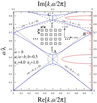
Fig. 2 shows the dispersion characteristics of a structure with the structural and geometrical parameters given in the inset. Here, the dashed lines represent the unperturbed dispersion curves that
are plotted for the case of kx = 0. By the Floquet approach, the dispersion curves of a TE-wave are
calculated with the results shown in blue for the real part of kya/2π and in red for the imaginary part,
respectively, as a function of koa/2π. Evidently, we have three types of stop band, as marked by A, B
and C. The stop-band A is due to the interactions between the two space harmonics labeled by the indices (m = 0, n = 0) and (m = 0, n = -1). The stop-bands B and C can be similarly identified with an interaction between other two space harmonics. The relative widths among the three types of stop bands may be explained in terms of the order of interacting harmonics.
Fig. 3 shows the transmission efficiency of a 2D periodic structure with 10, 20 and 30 layers, respectively. The structure is illuminated by a TE plane wave at the normal incidence. As expected, there exist three stopbands, as also marked by A, B and C. Evidently, as the number of 1D periodic layers is increased, the transmittance is reduced, so that the stopbands approach those of the infinite medium.
Figure 4 shows the variation of reflection efficiency versus incident angle for three different 2D periodic structures. The relative dielectric constant of the dielectric rods is 11.4 for all three cases. The short dash line in blue color is for the case of 16 1D periodic layers with the triangular lattice
pattern and the aspect ratios: a1/a=0.4, b1/b=0.2. The long dash line in red color is for the case of 16
1D periodic layers with the rectangular pattern and the aspect ratio: a1/a=0.6, b1/b=0.2. The black
line with triangle symbol attached is the case for the composite structure that consists of the above two 2D periodic structures in cascade. It is noted that the triangular pattern yields the total reflection
except for the angles around 8o and 62o, whereas the rectangular one has the total reflection around
3
structure exhibits perfectly total reflection at any incident angle.
5. Conclusions
We have employed the two different approaches to the problem of wave propagation in a 2D periodic medium. Extensive numerical results have been obtained to examine the stopband behaviors of various structures with different array patterns; in particular, it is shown that a composite structure consisting of two 2D periodic layers of different array patterns can produce the total reflection at any incident angle.
References
1. Attila Mekis, Shanhui Fan, and J. D. Joannopoulos, “Absorbing boundary conditions for FDTD simulations of photonic crystal waveguides”, IEEE Microwave and Guided Wave Letters, Vol. 9, No. 12, pp502-504, December 1999.
2. R. P. Larsen and A. A. Oliner, ”A new class of low loss reactive wall waveguides”, 1967 G-MTT International Microwave Symposium Program and Digest, pp. 17-22.
3. S. T. Peng, "Rigorous formulation of scattering and guidance by dielectric grating waveguides: general case of oblique incidence," J. Opt. Soc. Am. Vol. 6, 1869-1883 (1989).
S
a
a
1b1
b
Figure 1: Geometric conf iguration of 2D periodic array
εs
ε
a εs A B C 0.3 0.35 0.4 0.45 0.5 0.55 0.6 0.65 0.7 0.75 0.8 0.85 0.9a/
λ 0 0.1 0.2 0.3 0.4 0.5 0.6 0.7 0.8 0.9 1 T ransmission E ff iciency 10 layers 20 layers 30 layers a=b a1/a=b1/b=0.5 ε1=4.0 ε2=1.0 Normal IncidenceFigure 3: Transmission ef f iciency versus wavelength of a stack of 1D periodic layers
a b
4 0 0.1 0.2 0.3 0.4 0.5 0.6 0.7 0.8 0.9 1
Re[k
ya/2
π
]
0 0.1 0.2 0.3 0.4 0.5 0.6 0.7 0.8 0.9a
/
λ
0.2 0.1 0Im[k
ya/2
π
]
0 0.1 0.2 0.3 0.4 0.5 0.6 0.7 0.8 0.9 (m = 0, n = 0) (m = 0 , n = -1 ) (m = -1, n = 0) (m = -1, n = -1) a = b a1/a=b1/b=0.5 ε1=4.0 ε2=1.0Figure 2: Dispersion relation f or the 2D periodic medium;
Compute ky f or a given kx=0 a b x-axis y-axis A B C 0 10 20 30 40 50 60 70 80 90
Incident Angle (degree)
0 0.1 0.2 0.3 0.4 0.5 0.6 0.7 0.8 0.9 1 1.1 1.2 1.3 1.4Re
flecta
n
ce
0 10 20 30 40 50 60 70 80 90--- a1/a = 0.4, b1/b = 0.2, s = 0.5a, 16 1D periodic layers
--- a1/a = 0.6, b1/b = 0.2, s = 0, 16 1D periodic layers
---composite structures (32 1D periodic layers)
Figure 4: Variation of ref lectance versus incident angle f or various types of lattice pattern