0925-9635/03/$ - see front matter䊚 2003 Elsevier Science B.V. All rights reserved. doi:10.1016/S0925-9635(03)00209-7
The role of nitrogen in carbon nanotube formation
Chao Hsun Lin , Hui Lin Chang , Chih Ming Hsu , An Ya Lo , Cheng Tzu Kuo *
a,b a a a a, Department of Materials Science and Engineering, National Chiao Tung University, Hsinchu 300, Taiwan, ROC aPhotoetching Laboratory, Materials Research Laboratories, Industrial Technology Research Institute, Hsinchu 310, Taiwan, ROC b
Abstract
To examine the role of nitrogen, Co- and Ni-coated substrates were pretreated with three different gas compositions to compare the pretreated catalyst surfaces; the Fe, Co and Ni foils were subjected to carbon nanotube(CNT) growth experiments with CH y4
H and CH2 4yN as source gases; the catalyst pretreatment plus the CNT growth experiments on Co- and Ni-coated Si substrates2
were carried out using both microwave plasma chemical vapor deposition and electron cyclotron resonance chemical vapor deposition(ECR-CVD) under different nitrogen-containing gases. The results show that the role of nitrogen may be summarized
as follows: by comparing with hydrogen plasma, the bombardment energy of nitrogen plasma is greater. Therefore, the presence of nitrogen during CNT growth can keep the front catalyst surface clean and active to prolong surface passivation to enhance carbon bulk diffusion. The higher temperature due to higher bombardment energy of nitrogen plasma can promote agglomeration effects during catalyst pretreatment and the initial stage of CNT growth to produce larger size nano-particles. The presence of nitrogen is a favorable condition for formation of the bamboo-like CNTs, but not a necessary condition. Another favorable condition for formation of the bamboo-like CNTs is to deposit CNTs by ECR-CVD.
䊚 2003 Elsevier Science B.V. All rights reserved.
Keywords: Nitrogen; Formation mechanism; Bamboo-like nanotubes; Chemical vapor deposition
1. Introduction
Since the discovery of carbon nanotube (CNT) by
Iijima through the arcdischarge method w1,2x, the nanostructured materials have become the hottest research topics in the world including their synthesis methods, growth mechanisms, property measurement, computational modeling, manipulation techniques and their potential applications w3x. The CNTs high Young’s modulus (f1.8 TPa) w4x, high aspect ratio structure, low density and unique electrical properties make them promising materials for use as tips of scanning tunneling microscope or atomic force microscope w5x. The excel-lent field emission properties also make them suitable as electron field emitters for field emission displays
w6,7x. The assembly of CNTs into electronic circuits or
as a field-effect transistor have pointed out an amazing future for nanotube electronic and spintronic device applications w8–13x. However, the mechanical and elec-*Corresponding author. Department of Materials Science and Engi-neering, National Chiao Tung University, 1001 Ta-Hsueh Road, Hsinchu 300, Taiwan, ROC. Tel.: 5731949; fax: q886-3-5721065.
E-mail address: ctkuo@cc.nctu.edu.tw(C.T. Kuo).
trical properties of CNTs are highly depending on their chirality, diameter and structural defects w14x.
The single-walled carbon nanotubes(SWNTs) have a more perfect graphite layer and can be synthesized by laser ablation or arcdischarge methods w14x. However, the as-grown deposits from the above methods need post purification processes, and the lack of well devel-oped manipulation techniques so far retards the schedule of CNT commercialization. The chemical vapor depo-sition (CVD) methods, including microwave plasma
enhanced CVD(MPCVD) w15–20x, thermal CVD w21–
25x, hot filament CVD and electron cyclotron resonance CVD (ECR-CVD) w27x, can directly be used to grow the aligned CNTs on a substrate. Moreover, the catalyst filmyparticle on the substrate can be patterned by many
methods, such as lithography, transfer printing, evapo-ration or sputtering. The nanotubes can then be selec-tively grown on the catalyst-patterned substrates. The unique advantages of CVD methods, by comparing with other methods, are no need of post-treatments, i.e. purification and manipulation, and the ease of scaling up for mass production. But, its main disadvantage is the tendency to mainly form MWNTs with larger diam-eter and more defects, instead of SWNTs. The
‘hol-Table 1
Plasma pretreatment conditions for Co and Ni catalysts by MPCVD method
Specimen Catalyst Gas Flow rate Pressure Power Time
designation (thickness in nm) (sccm) (Torr) (W) (min)
P1 Co(10) H2 100 16 600 10 P2 H2yN2 90y10 16 P3 NH3 100 9 P4 Ni(10) H2 100 16 P5 H2yN2 90y10 16 P6 NH3 100 9 Table 2
Specimen designations of CNTs deposited by MPCVD method
Specimen Catalyst Gas Flow rate Pressure Power Time
designation (thickness) (sccm) (Torr) (W) (min)
F1 Fe foil(0.5 mm) CH4yH2 10y100 16 960 10 F2 CH4yN2 10y100 16 960 10 F3 Co foil(0.5 mm) CH4yH2 10y100 16 960 10 F4 CH4yN2 10y100 16 960 10 F5 Ni foil(0.5 mm) CH4yH2 10y100 16 960 10 F6 CH4yN2 10y100 16 960 10 MP1 Co(7.5 nm) CH4yN2 10y100 16 960 10 MP2 Co(7.5 nm)ySiO (10 nm)2 CH4yN2 10y100 16 960 10 MP3a CoSi x CH4yN2 10y100 16 960 10
Pretreatment conditions of all specimens: H 10 sccm, 16 Torr, 960 W, 10 min.2
The catalyst for specimen MP3 was prepared by coating with 7.5 nm Co film and followed by two-step rapid thermal annealing in N a
2 atmosphere at 600 8C for 60 s and 760 8C for 20 s to form CoSi .x
lowed’ and ‘bamboo-like’ structures of CVD-grown MWNTs have seen investigated thoroughly w15–38x. It is believed that the bamboo-like MWNTs possess higher defect density than the hollow MWNTs and the SWNTs. The influence of nitrogen on the growth mechanism of carbon-based materials has also been previously investigated w15–38x. Kurt and Karimi w39x found that as the amount of nitrogen increases, the alignment of the CNT lattice is gradually lost. Jung et al. w33x proposed that the role of nitrogen would be either to enhance the formation of graphite layer on the catalyst surface or to increase the separation of the graphitic layers from the catalyst. The change in the reaction kinetics at the catalyst surface due to activated nitrogen plays a key role for the bamboo-like CNT growth. Ma et al. w38x and our studies by MPCVD w27x also demonstrated that nitrogen can enhance bamboo-like CNT formation. However, we found that the bamboo-like CNTs can often be formed with or without the presence of nitrogen in the ECR-CVD system. The purpose of this work was to examine the effects of nitrogen during catalyst pretreatment and CNT growth stages on the structure of CNTs.
2. Experimental
To examine the role of nitrogen, three experiments were carried out. For the first MPCVD experiment, the
Co- and Ni-coated substrates were pretreated with three different gas compositions (i.e. hydrogen, hydrogeny
nitrogen or ammonia plasma) to compare the pretreated
catalyst surfaces. The detailed conditions are shown in Table 1. For the second experiment, the Fe, Co and Ni foils were subjected to CNT growth experiments with CH4yH and CH yN2 4 2 as source gases. The detailed conditions are shown in Table 2. The depth profiles of the metal foil substrates after wiping off the CNTs were analyzed by secondary ion mass spectrometry (SIMS). For the third experiment, the catalyst pretreatment plus the CNT growth experiments on Co- and Ni-coated Si substrates were carried out by using both MPCVD and ECR-CVD under different nitrogen-containing gases. For MPCVD experiments, the temperatures of catalyst pretreatment and CNT deposition could reach 600–650
8C due to plasma heating. For the ECR-CVD
experi-ments, the temperatures of the catalyst-coated substrate during pretreatment and CNT deposition were ;650 8C by providing additional electrical heating, and an 875 G magneticfield strength was applied to maintain the ECR condition. The specimen designation, catalyst pretreat-ment and CNT deposition conditions are shown in Tables 2 and 3 for MPCVD and ECR-CVD, respectively. The deposited nano-structures were characterized by field emission scanning electron microscopy (SEM), transmission electron microscopy (TEM), and high-resolution transmission electron microscopy.
Table 3
Specimen designations of CNTs deposited by ECR-CVD method
Pretreatment Specimen designa-tion and their dep-osition conditions ECR1 ECR2
Catalyst Ni Co
Gas sources H2 CH4 CH4yN2
Flow rate(sccm) 20 20 18y2
Working pressure(mTorr) 2–3 2–3 2–3
Microwave power(W) 800 800 800
DC bias(V) y100 y100 y200
Temperature(8C) ;650 ;630 ;630
Time(min) 10 15 20
3. Results and discussion
3.1. The effect of nitrogen content during plasma catalyst pretreatment
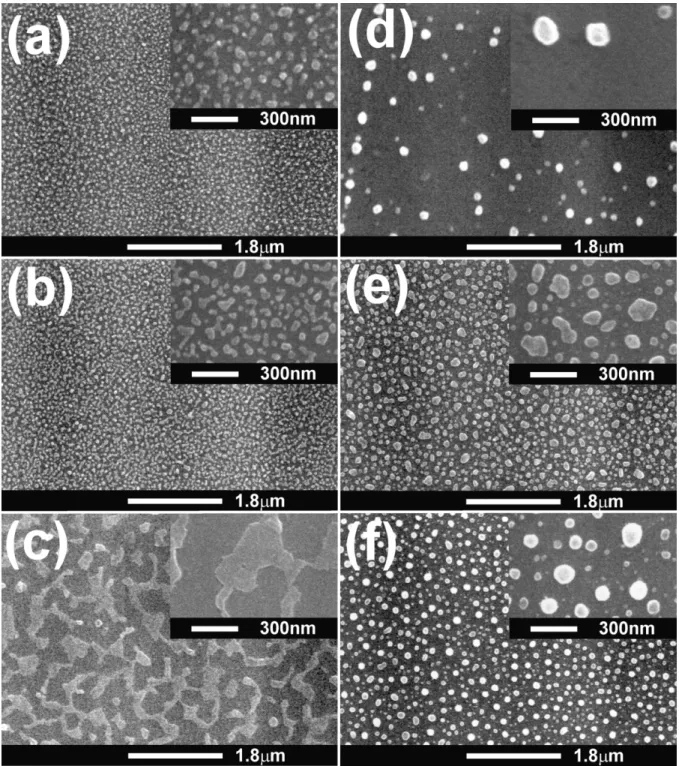
It is known that absorption of carbon by catalyst from the gas phase and precipitation of carbon to form CNTs are just part of the catalytic reactions. The growth of CNTs can involve many complicated catalytic steps including surface conditions due to reactions in plasma catalyst pretreatment. In order to examine the effect of nitrogen content in the plasma pretreatment on subse-quent catalytic reactions during CNT growth, three catalyst pretreatment atmospheres with different nitrogen contents were studied (as listed in Table 1). The SEM micrographs of the catalyst-pretreated substrates are shown in Fig. 1. For the Co catalyst, the pretreated catalyst surfaces by three different plasma atmospheres are depicted in Fig. 1a, b and c, respectively. It is obvious that the pretreated surface in Fig. 1c by ammo-nia plasma is quite different from other two surfaces, where the plasma contains the highest percentage of nitrogen. In other words, the higher momentum of nitrogen plasma may give rise to a greater bombardment energy and temperature to agglomerate or melt more nano-particles to become bigger particles. It may follow by reacting with the Si substrate to form Co-silicide to become many inter-connected islands. For the Ni cata-lyst, similar phenomena are observed in Fig. 1d, e and f, where the particles in Fig. 1f become spherical in shape, signifying that the melting occurs during pretreat-ment. Different pretreatment behaviors between Co and Ni catalysts may relate to the difference in activation energy of reactions with the Si substrate to form silicides of Co and Ni. This is in agreement with the fact that it is more difficult to form Ni-silicides than Co-silicides. It is also noted that the particle density in Fig. 1d is the smallest among them. This may relate to lower energy of the hydrogen plasma compared with the nitrogen plasma attacking the Ni film to produce nano-particles. The results here signify that the pretreatment plasma can be used to manipulate the favorable surface
condi-tions for subsequent CNT growth. The effect of nitrogen content in the pretreatment plasma on growth of the catalyst-assisted CNTs is under investigation.
3.2. The effect of nitrogen on carbon diffusion during CNT growth
There are many reports directly w38x or indirectly
w22,33,34x; w40x to prove that the nitrogen-contained
plasma can induce bamboo-like CNT formation. How-ever, it is well known that catalytic reactions during CNT growth can involve very complicated processes. The first involves the selectivity effect (composition
effect) of the catalyst, so that the same precursor through
different catalytic reactions may result in different prod-ucts. The second involves the adsorption or absorption on the catalyst surface, which would change the catalyst surface energy and its electronic state. The third involves the structure of the catalyst, such as, particle size, crystallographic structure and surface compositions, where the catalytic reaction is often structure sensitive.
In order to examine the effect of nitrogen on CNT growth, three different pure metal foils(Fe, Co and Ni)
approximately 0.5 mm thick were used as substrates and pretreated by hydrogen plasma and than followed by CNT growth by MPCVD under CH4yH and CH yN2 4 2
atmospheres, respectively. The detailed conditions are shown in Table 2 (specimens F1–F6). The
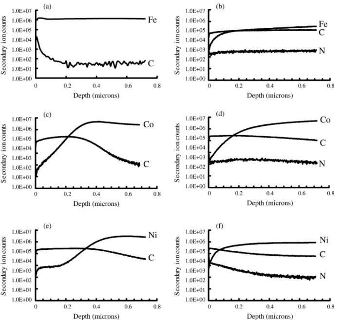
catalyst-assisted CNTs on metal foils were then wiped off by a cloth with alcohol. The CNT-wiped metal foils were followed by depth profile analyses of SIMS with a 5 A˚ys sputtering rate. The depth profiles of three
CNT-wiped metal foils are shown in Fig. 2a, cand e for a CH4yH plasma atmosphere, and Fig. 2b, d and f for a2
CH4yN plasma atmosphere, respectively. Under a CH y2 4
H2 plasma atmosphere, it indicates that the carbon concentration is a rapidly decreasing function of depth; especially showing an abrupt drop approximately 0.2
mm depth. In contrast, under the CH4yN plasma atmos-2
phere, the carbon concentration is a more slowly decreasing function of depth. The carbon concentration at 0.7 mm depth remains significant. In other words, the presence of nitrogen can enhance carbon diffusion into the catalysts. This may relate to the enhanced bombard-ment effect of the nitrogen plasma compared with that of the hydrogen plasma in delaying the surface passi-vation. A clean catalyst surface from the proper bom-bardment may provide a high diffusion site density for carbon diffusion. Furthermore, it is noted that a signifi-cant amount of nitrogen atoms diffuse into the Fe, Co and Ni metal foils. This implies that the crystallographic structure and compositional changes may also cause variation in catalytic reactions, as mentioned in the previous paragraph.
3.3. The role of nitrogen in bamboo-like CNT formation
It was proposed that the presence of nitrogen is a main factor in forming the bamboo-like CNTs
Fig. 1. SEM micrographs of the pretreated catalyst-coated substrates for different catalyst materials and pretreatment conditions:(a) Co (specimen
P1); (b) Co (specimen P2); (c) Co (specimen P3); (d) Ni (specimen P4); (e) Ni (specimen P5); and (f) Ni (specimen P6). The corresponding
insets are at the higher magnifications.
w22,33,34,38x. From SIMS analysis in the previous
section, it seems to indicate that the presence of nitrogen can more greatly enhance the carbon diffusion. In order to examine the role of nitrogen on bamboo-like CNT formation, both MPCVD and ECR-CVD methods were adopted to grow CNTs using different nitrogen contain-ing atmospheres. The detailed deposition conditions are shown in Tables 2 and 3 for MPCVD and ECR-CVD
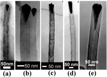
methods, respectively. The results show that the bamboo-like CNTs can only be formed with the presence of nitrogen in the MPCVD method. In contrast, for the ECR-CVD method, bamboo-like CNT can be produced with or without presence of nitrogen. The typical TEM micrographs of the bamboo-like CNTs by ECR-CVD and MPCVD methods are shown in Fig. 3a–e for specimens ECR1, ECR2, MP1, MP2 and MP3,
respec-Fig. 2. SIMS depth profiles of the metal foil substrates(Fe, Co and Ni foils) after wiping off the catalyst-assisted CNTs deposited under two
different atmospheres (CH yH s10y100 sccmysccm, or CH yN s10y100 sccmysccm): (a) Fe foil, CH yH (specimen F1); (b) Fe foil,4 2 4 2 4 2 CH4yN2(specimen F2); (c) Co foil, CH yH (specimen F3); (d) Co foil, CH yN (specimen F4); (e) Ni foil, CH yH (specimen F5); (f) Ni4 2 4 2 4 2 foil, CH4yN2(specimen F6).
tively. Fig. 3a shows a bamboo-like CNT without the presence of nitrogen (CH s20 sccm only). The typical4
SEM and TEM micrographs showing the morphologies of the bamboo-like CNTs by ECR-CVD and MPCVD methods are depicted in Figs. 4 and 5, respectively. Fig. 4 for a sample produced using the ECR-CVD method was taken after pressing down the CNTs to facilitate examination, and the inset is a magnified image to show the catalyst shape. The as-deposited CNTs are perpen-dicularly well aligned CNTs. The bamboo-like CNTs in Fig. 5 from the MPCVD method are spaghetti-like in shape, where nitrogen predominates the atmosphere
(CH yN s10y100 sccmysccm).4 2
From Figs. 3 and 4, it is worth noting that the shapes of the catalysts can be divided into three groups, i.e. pear-like, pyramid-like and cork-like. Another fourth group in Fig. 3e is the typical shape of base-growth CNTs due to strong chemical bonding with the substrate. The results show that the pear-like catalysts (Fig. 3a, for Ni catalyst) are often found on CNTs deposited
without the presence of nitrogen by both MPCVD and ECRCVD methods. In contrast, with the presence of nitrogen, the pyramid-like catalysts (Fig. 3b, for Co
catalyst) are predominant on CNTs deposited by the
ECR-CVD method, and the cork-like catalysts (Fig. 3c
Fig. 3. TEM micrographs of the bamboo-like CNTs deposited by ECR-CVD or MPCVD at different gas compositions:(a) Ni catalyst,
CH4 plasma (specimen ECR1); (b) Co catalyst, CH yN plasma4 2
(specimen ECR2); (c) Co catalyst, CH yN plasma (specimen MP1);4 2
(d) Co catalyst, CH yN plasma (specimen MP2); (e) CoSi catalyst,4 2 x
CH4yN plasma2 (specimen MP3).
Fig. 4. Typical SEM micrographs of the ECR-CVD grown CNTs after pressing down the tubes(Specimen ECR1).
Fig. 5. Bamboo-like CNTs grown by MPCVD(specimen MP1). As regards the sizes of CNTs or catalysts, it was
found that the sizes of catalysts or CNTs or both are often smaller for CNTs deposited with CH4yH than2
with CH4yN by MPCVD or ECR-CVD methods. Such2
a difference in size is more obvious for CNTs grown via MPCVD. The sizes of CNTs less than 5 nm are attainable by MPCVD without the presence of nitrogen. For the ECR-CVD method, the sizes of most CNTs as in Fig. 3a are smaller than in Fig. 3b. This may be explained by the lower bombardment energy of the hydrogen plasma compared to the nitrogen plasma. In other words, the higher surface temperature due to nitrogen bombardment may enhance the agglomeration effect causing more nano-particles to melt together to become bigger catalysts and therefore CNTs. The smaller catalyst was proposed to favor the growth of hollowed CNTs w32x. Because, as the size of catalyst particle decreases, the ratio of surface area to volume would increase and the surface diffusion of carbon would dominate, instead of the bulk diffusion. However, this statement seems to be not applicable to CNTs synthe-sized by ECR-CVD. The catalyst size of ;20 nm in Fig. 3a is small in size, but it forms bamboo-like CNTs instead of hollowed CNTs, even though there is no nitrogen present. As mentioned in the previous para-graph, the bamboo-like CNTs can be formed with and without the presence of nitrogen using ECR-CVD. The reason behind this may be reasoned by the following arguments: the working pressure of ECR-CVD is in the millitorr range, lower than typical ranges used in thermal CVD or MPCVD(1–100 Torr). It means that the carbon
concentration in the ECR-CVD system is much less, though the concentration of the dissociated species is higher. In other words, the activity and cleanness of the
top surface of the catalyst particles are higher in the ECR-CVD system, and this will provide more adsorption andyor accommodation sites on the catalyst surfaces for
diffusion of carbon species. This will greatly promote more inner precipitation sites at the bottom surfaces of the catalysts to form the bamboo-like CNTs.
What is the formation mechanism of the bamboo-like CNTs? From the present results, the following parame-ters seem to aid in promoting the formation of bamboo-like CNTs: (1) the presence of nitrogen or other heavy gases; (2) keeping an active and clean top surface of the catalyst particles; (3) prolonging carbon bulk diffu-sion of the catalysts; (4) larger catalyst size; and (5) preventing atmosphericreactions to form a passivation layer on the catalyst surfaces. Conditions (2) and (3)
can explain the reasons why ECR-CVD often forms bamboo-like CNTs. The presence of nitrogen is essen-tially to fulfill conditions(2) and (3).
4. Conclusions
The results of the catalyst pretreatment experiments by using three different nitrogen-containing gases signify that the pretreatment plasma can be used to manipulate favorable surface conditions for subsequent CNT growth. The results of the CNT growth experiments with Fe, Co and Ni catalyst foils as substrates and CH4y
H or CH2 4yN as source gases indicate that the presence2
of nitrogen can enhance the carbon diffusion in the catalyst foils. The experiments on CNT growth by both MPCVD and ECR-CVD under different nitrogen-con-taining atmospheres were conducted. The results show that the presence of nitrogen can promote formation of the bamboo-like CNTs, but they can also be formed without the presence of nitrogen using ECR-CVD. By comparing with hydrogen, the role of nitrogen during catalyst pretreatment and possibly at the initial stage of CNT growth is to promote nano-particle agglomeration due to greater bombardment energy. The role of nitrogen in CNT growth or bamboo-like CNT formation is basically to prolong the passivation of the front catalyst surface to enhance carbon diffusion.
Acknowledgments
This work was supported by the National Science Council (contract no.: NSC90-2216-E-009-040, -034,
-035) of Taiwan. References
w1x S. Iijima, Nature 354(1991) 56.
w2x S. Iijima, T. Ichihashi, Nature 363(1993) 603.
w3x R.W. Seigel, in: G.M. Holdridge(Ed.), Nanostructure Science
and Technology, Kluwer Academic Publishers, Netherlands, 1999, pp. 1–13.
w4x M.M.J. Treacy, T.W. Ebbesen, J.M. Gibbson, Nature 381 (1996) 678.
w5x H. Dai, J.H. Hafner, A.G. Rinzler, D.T. Colbert, R.E. Smalley,
Nature 384(1996) 147.
w6x J.M. Kim, W.B. Choi, N.S. Lee, J.E. Jung, Diamond Relat.
Mater. 9(2000) 1184.
w7x J.M. Bonard, J.P. Salvetat, T. Stockli, L. Forro, A. Chatelain,
Appl. Phys. A 69(3) (1999) 245.
w8x H. Dai, E.W. Wong, C.M. Lieber, Science 272(1996) 523. w9x R. Martel, T. Schmidt, H.R. Shea, T. Hertel, P.H. Avouris,
Appl. Phys. Lett. 73(1998) 2447.
w10x S.J. Tans, A.R.M. Verschueren, C. Dekker, Nature 393(1998)
49.
w11x H. Dai, J. Kong, C. Zhou, et al., J. Phys. Chem. B 103(1999)
11246.
w12x P.G. Collins, M.S. Arnold, P. Avouris, Science 292 (2001)
706.
w13x Y. Huang, X. Duan, Q. Wei, C.M. Lieber, Science 291(2001)
630.
w14x H.S. Nalwa, Handbook of Nanostructured Materials and
Nan-otechnology, vol. 5, Academic Press, San Diego, 2000.
w15x S.H. Tsai, C.W. Chao, C.L. Lee, H.C. Shih, Appl. Phys. Lett.
74(1999) 3462.
w16x H. Murakami, M. Hirakawa, C. Tanaka, Appl. Phys. Lett. 76 (2000) 1776.
w17x V.I. Merkulov, D.H. Lowndes, Y.Y. Wei, G. Eres, E. Voelkl,
Appl. Phys. Lett. 76(2000) 3555.
w18x C. Bower, W. Zhu, S. Jin, O. Zhou, Appl. Phys. Lett. 77 (2000) 830.
w19x C. Bower, O. Zhou, W. Zhu, D.J. Werder, S. Jin, Appl. Phys.
Lett. 77(2000) 2767.
w20x K.B.K. Teo, M. Chhowalla, G.A.J. Amaratunga, W.I. Milne,
Appl. Phys. Lett. 79(2001) 1534.
w21x J. Li, C. Papadopoulos, J.M. Xu, M. Moskovits, Appl. Phys.
Lett. 75(1999) 367.
w22x C.J. Lee, J. Park, Appl. Phys. Lett. 77(2000) 3397. w23x Y Avigal, R Kalish, Appl. Phys. Lett. 78(2001) 2291. w24x J.I. Sohn, S. Lee, Y.H. Song, S.Y. Choi, K.I. Cho, K.S. Nam,
Appl. Phys. Lett. 78(2001) 901.
w25x Y.Y. Wei, G. Eres, V.I. Merkulov, D.H. Lowndes, Appl. Phys.
Lett. 78(2001) 1394.
w26x Y. Chen, D.T. Shaw, L. Gou, Appl. Phys. Lett. 76 (2000)
2469.
w27x H.L. Chang, C.H. Lin, C.T. Kuo, Diamond Relat. Mater. 11 (3–6) (2002) 793.
w28x C.H. Lin, H.L. Chang, M.H. Tsai, C.T. Kuo, Diamond Relat.
Mater. 11(3–6) (2002) 922. w29x Y. Saito, Carbon 33(1995) 979.
w30x O.A. Louchev, Y. Sato, Appl. Phys. Lett. 74(1999) 194. w31x C.J. Lee, J. Park, S.Y. Kang, J.H. Lee, Chem. Phys. Lett. 323
(2000) 554.
w32x C.J. Lee, J.H. Park, J. Park, Chem. Phys. Lett. 323 (2000)
560.
w33x M. Jung, K.Y. Eun, Y.J. Baik, et al., Thin Solid Films 398–
399(2001) 150.
w34x H. Cui, O. Zhou, B.R. Stoner, J. Appl. Phys. Commun. 88 (10) (2000) 6072.
w35x Z.F. Ren, Z.P. Huang, J.W. Xu, et al., Science 282 (1998)
1105.
w36x X. Wang, W. Hu, Y. Liu, et al., Carbon 39(2001) 1533. w37x V.V. Lovalevski, A.N. Safronov, Carbon 36(1998) 963. w38x X. Ma, E. Wang, D.A. Jefferson, et al., Appl. Phys. Lett. 75
(1999) 3105.