794 IEEE Transactions on Consumer Electronics, Vol. 36, No. 4, NOVEMBER 1990
TRAINING SIGNAL AND RECEIVER DESIGN FOR MULTI-PATH CHANNEL
CHARACTERIZATION FOR TV BROADCASTING
J.-D. Wang, T.-H. S. Chao*, and B. R. Saltzberg
AT&T Bell Laboratories
*Department of Telecommunication Engineering
National Chiao-Tung University, Taiwan
ABSTRACT
The problem of multi-path propagation in television terrestrial broadcasting can be solved by channel equalization. The use of such equalization is needed for an enhanced NTSC system and is particularly critical in most HDTV proposals. We propose techniques for precisely characterizing a multi-path channel. T h e s e c h a r a c t e r i z a t i o n s c a n be used t o reduce h a r d w a r e complexity and to speed up equalizer convergence.
I. INTRODUCTION
In an NTSC broadcasting environment, ghosted pictures are the results of a multi-path channel, as shown in Figure 1. This is due to wave reflections from hills. buildings, airplane flutter, and so forth. The effect of ghosts in an NTSC receiver can be very annoying. Nevertheless, an NTSC system transmits and receives analog video signals. Ghosts appear as multiple weakened and delayed images of the original picture. Although a picture could be severely ghosted, it is usually comprehensible to a viewer. This results in a “graceful” degradation, not a disaster.
On the other hand, for an all-digital HDTV system the video signal is heavily encoded as digital data. Reliable data recovery at the receiver is needed for the video decoder to store the original picture. However, when data is distorted by multi-path ghosts, even weak ones, the receiver might not be able to correctly decide which data was transmitted based on the received signal. This can severely damage the video decoding process. Therefore, if ghosts are not properly cancelled, broadcasting a heavily compressed digital HDTV signal via a multi-path channel can result in a problem much more serious than just ghosted pictures. In a severe case, the received picture could be totally incomprehensible to a viewer.
Most existing H D T V systems, such as the MUSE system (Multiple Sub-Nyquist Sampling) in Japan or the MAC system in Europe, use simple analog video encoding schemes based on sub- Nyquist rate sampling. The sampled (“discrete-in-time”) analog video signal is pulse-shaped,l modulated and broadcast through DBS (Direct Broadcast Satellite). DBS provides a transmission channel which has a much less severe ghosting problem than broadcasting through a terrestrial channel. Also, due to the Jin-Der Wang and B. R. Salzberg are with AT&T Bell Laboratories T.-H. S. Chao IF with the Dept. of Telecommunication Engineering, National Chiao-Tung Univeruty, Taiwan
I Raised-cosine pulse shaping. which satisfies the Nyquist criterion. I S used to avoid interaymbol interference.
Ghosts A Result of Multi-Path Distortion
~~ ~
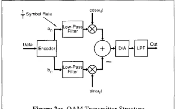
Multi-Path Equalization (Ghost Cancellation) Figure 1: Effect of Ghost on NTSC Pictures transmission of an analog encoded video signal, the effect of ghosts in DBS only results in very mildly ghosted pictures. Other HDTV systems such as the ones proposed by Zenith and MIT for terrestrial broadcasting use a hybrid transmission scheme. The critical encoded video data and encoded audio data are sent through a highly protected data channel and other encoded video signals are sent as “discrete-in-time” analog signal components. Before going further. we will describe the ghosting effect on a data transmission channel. The data transmission scheme that will m o s t p r o b a b l y be used is the s o - c a l l e d D a t a Q u a d r a t u r e Amplitude Modulation (QAM), as opposed to the analog QAM with which TV engineers are very familiar. As shown in Figure 2(a), two-dimensional discrete digital data elements (an, bn) are modulated and transmitted through an analog channel. As an
cosu~,it +Symbol Rate Encoder
-a
b”LptgJ-
1
sino,,tFigure 2a: Q A M Transmitter Structure Manuscript received October 19, 1990 0098 3063/90/0200 0794$01 .OO 1990 IEEE
Wang, Chao and Saltzberg: Training Signal and Receiver Design for Multi-path Channel Characterization
I Figure 2d: Gho\ted Signal Con5tellation
195
Figure 2b: +Point Signal Con\tellation example. \ b e only de\cribe a siniplc 5) stem using four-point QAM. In [hi\ case. two con\ecutive data bits itre mapped into a \ y m b o l which a \ u m e \ o n e of the f o u r p o i n t s i n a two- dimensional \ignal con\tellation. as shown in Figure ? ( b ) . The symbol ha\ two independent component\ c:tlletl the inphase and quadrature component\. They are further modulated with co\oiff and -
-
sinwifr rc\pectively and s u m m e d before being u p - converted for transmi\\ion. The IF \pecti-um is shown in Figure ?(c). When the \ign;iI is \en1 through the air. it i s corrupted b) multi-path di\tortion. After demodulation at the r e c e i i c r . the received \ymbols are di\torted and become ver) furz! its \hewni n Figure 2 ( d ) .
Kotc t h a t the dijtorted \ignal around each symbol point i n the constellation \pace rcscnihle\ the original \ignnl constellation w ith ;I reduction in strength. This i \ an interesting phenomenon cnused b! multi-path gho\t\ on data tr:in\niis\ion. I n Figui-e l i d ) . u e \how a c a w w i t h II mild multi-path distortion. I f the multi-path di\tortinn i\ \evere enough. it might not be po\sible to correctly \lice received \)nibol\ to ihe ori@nal tran\mitted \! mbol\. Thi\ can be a cti\a\ter for a digital or hybrid HDTV reccibcr. The greate\t iniprovcment of an enhanced NTSC \y\teiii conic\
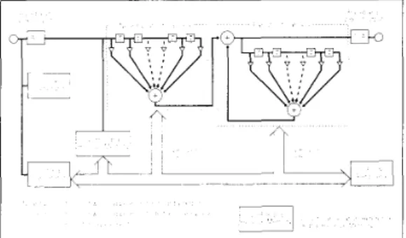
fi-om the proper removal of ghojts from recci\ed picture\. Figure .3 she\\ \ a generic NTSC dcyhosting (multi-path equalization) block diagT:ini \\ hich IS dewibed in a great deuil in [ I ] , Multi-
path channel equnlization h a \ also been a ci-ucinl issue for the \ u c c e s \ of ii true H D T V b r o a d c a ~ t i n ~ . e i t h e r IoI D B S
bmidcastin: or for terre\triiil brondcasting I\hich tran\mit\ either
an encoded analog \ ideo signal or encotled digital video data. Figure 1 \hoLb\ ;I data tran\mi\\ion \)\tern \I ith :I dcci\ion feedback multi-path e q u a l i x r at the rccci\ei.. How ever. equali/ing \uch a channel at a very high digital \ignal proces\ing rate o \ e r a \iide ghost delay rangc I \ still \er) costly for current technology. This i \ panicularl) true for tcrrestrial broadca\ting \\here gho\t\ x e \\ idely \pread and :in equali~er require\ hundred\ to thou\and\
Figure 2c: Spectrum
of filter taps ;it a rate around 15 M sainplcsisecond.
A c o m p a n i o n p a p e r
[ ? I
i n preparation will deal M i t h the i m pl e in e n t a t i o n of several reduced- c om ple x i t y equal i ze r \tructurcs for an enhanced NTSC receiver and for an HDTV receiver which utiliLes digital communications,. This paper will pi-irnarily deal with t e c h n i q u e s for precise T V c h a n n e l c h ;t r ac t e r i 7 at i on , T h e info r ni at i o n ob t a i n e d from c h a n n e Icharacteriiation c a n be u\ed to set up a multi-path equalizer (ghmt canceller). The channel information is valuable is many a\pccts which will be di\cussetl in the next section.
11. C H A W E L CHARACTERIZI-ITION FOR M C III' I PATH
Eo
C A I, IZ
AT1 0 hChannel characteri7otion (identification) can be described as follow\. At the traiisniitter. a known training {ignal (ghost cancellation relerence \ignal. GCR) is writ through the unknown channel. At the receiver. the observed received signal is used to characteri/c the channel. We define A ( / j a s the training (GCR) \ipiinl frequenc! \pectrum. / f t f f ) as the transmitter frequency rc\ponsc. H,.if) as the multi-path frequency response. H,,(fi ;IS the t u n e r lrequenc) i-e\ponse. H I / / a s the channel characterizcr'\ frecluenc) response at the receiver. and T ( f ) its the total frequency re\ponse.
where H!f is the overall transfer function. I f A f ) B ( f / equals a constant
X
o \ c r the transmisjion band. Tifi -=X
H ( f ) . and the channel informntion i\ obtained. Going through a certain filter design procedure u\ing channel information yields equalizer tap coefficient\. This c m \peed up equalirer convergence in order to track it tiiiie-\ar! ing multi-path channel. Also. because the multi-196 IEEE Transactions on Consumer Electronics, Vol. 36, No. 4, NOVEMBER 1990
Feedback F,l,P,
Figure 4: Multi-Path Equalization
path channel for TV broadcasting typically consists of relatively few significant and widely spaced responses, channel information can be used to constrain filter taps so as to reduce hardware complexity. Therefore, it would be useful to obtain precise channel information. In this paper, we will describe techniques for precisely characterizing a multi-path channel; one for an enhanced NTSC system and another for a spectrum compatible HDTV. Our proposed techniques can also provide various kinds of information for synchronization, automatic gain control, and carrier phase offset estimation. As an example, for an enhanced NTSC receiver our proposed GCR signal sequence can be used as a means to acquire synchronization, even if the received signal is severely ghosted or affected by impulse noise to the extent that the conventional synchronization scheme using synchronization pulses does not work.
If the channel is corrupted by noise, T u ) = k H(fl
+
N l f ) , where N u ) is the noise spectrum and k is the processing gain. The ratio k/N(fl, integrated over the transmission band, defines the signal- to-noise ratio. The larger the processing gain, the better the protection of channel information from the noise.Review of the BTA's Approach
The BTA (Broadcasting Technology Association) in Japan proposed a simple channel characterization scheme for the enhanced NTSC system, which has a processing gain that is smaller than one. Conceptually, a truncated (in time) sin x/x pulse with a smooth passband of 4.2 MHz, surrounded by zero signal, is transmitted over a multi-path (ghosted) channel. At the receiver, a response composed of the sin x /x waveform and its associated ghosts is obtained. This response contains the multi-path channel information. The zero signal surrounding the sin x/x waveform i s
needed to warrant that the multi-path channel response is not interfered with ghosts of the preceding and the succeeding signals. To avoid a possible DC bias problem in an NTSC system, the GCR signal is actually a truncated sin x/x pulse of 4.2 MHz bandwidth integrated over 44.7 p e c o n d s and terminated by a 2T trailing edge (this signal is referred to as a wide-bar signal). This signal i s inserted in line 18 during the blanking interval of a field and it i s paired with a zero pedestal signal in line 18 of another field. A pair-wise fixed signal in line 17 at the above-mentioned fields is required in order to obtain interference-free GCR signals. After receiving the paired GCR signal, the ghosted zero pedestal signal in line 18 is subtracted from the ghosted integrated sin x/x GCR signal in line 18 of another field. By using this subtraction method, ghosts from the preceding pair-wise fixed signal are cancelled. This eliminates the need of sending surrounding zero signals. Therefore, using a limited time span a larger ghost
detection range can be accommodated. Another paired GCR signal is also transmitted at line 281 (253 lines or one field from line 18). To overcome the color burst phase reversal between fields, a paired GCR signal interleaved four times in an 8-field sequence format was designed by BTA [ 11. The zero pedestal signal is sent in the 4th field following its associated integrated sin x/x GCR signal. The paired GCR signal is interleaved four times in a 8-field sequence. (Other field sequences can also be used.) Conceptually, this GCR signal can be viewed as (sin x/x)/(I-D), where I/(l-D) is a discrete integration operation at a sampling rate of four times color subcarrier, about 14.32 MHz. At the receiver, the integrated sin x/x signal goes through a (I-D) one-clock difference operation which undoes the integration operation at the transmitter, and also provides a DC blocking function in order to eliminate possible DC bias in the system.
At the transmitter, the peak amplitude of the integrated sin x/x G C R signal is limited to about 75 IRE to avoid a possible nonlinear distortion at the receiver under a severe ghosting condition. This limits the amplitude of the sin x/x signal before integration to about 38 IRE. Since the amplitude of the original sinx/x signal is about one half the amplitude of the integrated GCR signal, it results in a 6 dB loss in the signal-to-noise ratio. At the receiver. one-clock difference operation, which restores the sinx/x signal, results in a 3 dB noise enhancement, or equivalently a 3 dB reduction in the signal-to-noise ratio. The total loss due to the need of eliminating DC bias in the system is about 9 dB. A similar scheme was proposed for the MUSE HDTV system.2 To improve the signal-to-noise ratio, the received GCR signal is averaged over several hundred fields before it is used. BTA proposed an average of about 5 seconds or 32 times over a %field sequence 11.41 to achieve 15 dB improvement in the signal-to- noise ratio. (Note that another 6 dB improvement in the signal-to- noise is achieved with an average over four pairs of the received GCR signal in a 8-field sequence.) The net improvement in 5 seconds is about 12 dB in the signal-to-noise ratio. In practice, when the channel is noisy, the 5-second averaging is performed over many iterations to obtain satisfactory channel information. This slows down the system convergence speed and makes the tracking of changing ghosts impossible.
In [3], results of field tests using the BTA approach was reported. T h i s work was conducted by the National Association of Broadcasters (NAB) and the the Association of Maximum Service Television (MSTV) in Atlanta, Georgia, with supports from NHK (Nippon Hoso Kyokai), BTA, ATTC (Advanced Television Test Center), and many local stations. In that report, results showed 2 The MUSE system uses a $in x/x waveform which a\wme\ a negligible DC hla\
Wang, Chao and Saltzberg: Training Signal and Receiver Design for Multi-path Channel Characterization 191 1 OdB 26 3 dBm 'DlV -1068 4 2 MHz
I /
Figure 6a: The Power spectrum of PN Signal at thc Correlator Output
that although the BTA sysrem generally improved the picture quality. in some instances it actually reduced the quality of the received picture. Usually this condition occurred when the signal level was weak (low signal-to-noise ratio). This is worse than just slow down the system convergence. Note that the field tests were conducted within the City Grade services areas. It can be expected that this problem can be more severe in remote service areas. As mentioned in the final report of BTA [4]. the ghost strength and phase tend to change constantly. It is desirable that the cancelling time be held down to within I second, taking into account airplane flutter, compatibility with future sync broadcast services, and other factors. Apparently, the BTAs approach does not meet this requirement.
In [ 3 ] . it was reported that homes with outdoor antennas displayed non-varying (stationary) ghosting conditions, and were largely corrected. However. homes with indoor antennas, such as rabbit- ears or monopoles for V H F and bow-ties or loops for UHF. experienced changing (dynamic) ghosts. These varying ghosting conditions were more prevalent where people were moving around in the room, swaying of trees, or vehicles passing by, etc. The BTA ghost canceller generally was not able to adequately compensate for, or track. these conditions. In these conditions, pseudo-ghosts (false ghosts) were actually added to an already ghosted picture. When a substantial (strong) ghost, usually a leading (pre-cursor) one. was encountered, the picture quality was also reduced. Malfunction of a synchronization separation circuitry under a strong ghosting condition might be attributed to this problem since the BTA system relies on an accurate count of horizontal synchronous pulses to determine the GCR signal insertion position. When this happens. the BTA system cannot acquire the GCR signal and therefore it does not work. In all, it was reported in 131 that the BTA system generally improved the
I
,
1I
Figure 6b: The Time Domain Correlator Output of PN Approach
picture quality by two steps based on a CCIR five-step ranking. However. the BTA system was unable to correct for ghosts in 7 4 of their observations. It can be expected that the percentage of failure of the BTA system should be higher if field tests were conducted in remote service areas. To partially solve problems encountered by using the BTA system. BTA [4] recommended to select the appropriate types of antenna, installation place, height, and direction. Apparently, this is not a desired solution in the United States of America.
In the comine sections. we will propose a new approach that provides an opportunity to track changing ghosts at a weak signal level (low signal-to-noise ratio).
Modification of the P N Sequence and the Correlator Response
I n our proposal to be described in this paper, a modified pseudo- random noise (PN) sequence and a properly designed correlator are used. Our correlator, matched to our modified PN sequence, provides 24 dB better noise rejection than that obtained from the use of a single pulse. N o long-term averaging is needed to improve the signal-to-noise ratio. Therefore, it has a better system convergence speed and provides a hope for tracking changing ghosts, or it can trade-off the speed of convergence with the usage of VBI (vertical blanking interval) by sending the GCR signal less frequently. Our proposed correlator has a very low DC gain and provides an equivalent blocking function as the one-clock difference operation in BTA's proposal. Also, our proposed scheme provides rejection of other kinds of impairments, such as impulse noise. ignition noise, or colored noise, for which the long- term averaging is not effective.
One well-known method for channel identification is to send a pseudo-random noise sequence over a channel and to correlate the received sequence with that sequence. A unique property of a PN sequence with a length of N symbols is that when its repetitions are continuously correlated by the correlator, the correlator output results in large peaks separated by quiet zones of N-l samples with a negative DC value, which is N times smaller than the large peaks in magnitude. When transmitting PN sequences over a channel with ghosting conditions. the quiet zone becomes c o r r u p t e d with p u l s e s which c o r r e s p o n d t o the g h o s t i n g conditions. In this quiet zone, each ghost appears as a weakened, delayed, and possibly phase-rotated replica of the direct signal. This permits the multi-path channel response to be characterized with respect to amplitude, phase, and delay. This method has the advantage of providing significant correlation gain against channel noise. However, there are many pitfalls i n such an approach. One problem is that a quiet zone between the correlator peaks has nonzero DC values which would disturb the channel characterimtion of weak ghosts and possibly create problems for equalization. This problem can also be understood from a frequency domain point of view. The associated frequency spectrum of a nominal PN sequence is not flat. If N is the number of symbols in a PN sequence. the DC component has a magnitude that is
dN
times in magnitude (or N times in power) smaller than the rest of the frequency components. For this reason. a nominal PN sequence is not adequate for exactly characterizing the channel information. Another problem is that correlating to the received input could require N multiplications-and-additions in each symbol period. which presents a significant overhead in hardware complexity. To overcome these problems, our schemes require modifications of the nominal P N sequence and its associated correlator.798 IEEE Transactions on Consumer Electronics, Vol. 36, No. 4, NOVEMBER 1990 -\r TRANSMITTER ( 1 + bias, - I + hias)
I /
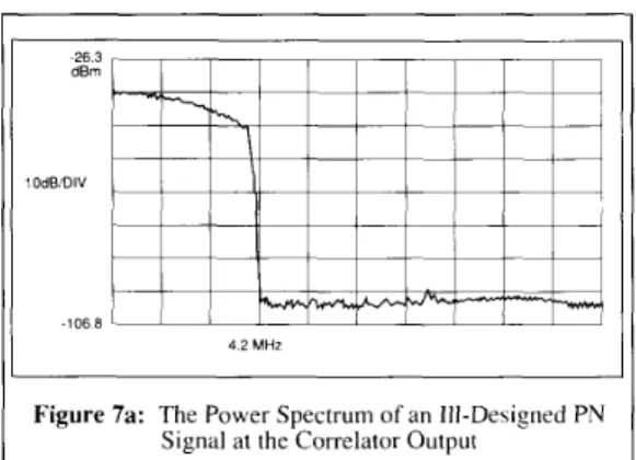
4 2 MHz A T C O R R E I . A T O R ( I + hias. - I + hiaslFigure 7a: The Power Spectrum of an Ill-Designed P N Signal at the Correlator Output
A PN sequence and the associated correlator will be modified in such a way that the product of their frequency spectra has a flat response in order to obtain an exact channel characterization. However, for simplicity in the circuitry, this flat response property should be obtained under the constraint that correlating with the received input only requires N additions or subtractions in each symbol period, with no multiplications. Therefore, the correlator can be cost-effectively implemented for a real-time operation. One can argue that this i s not a concern if the correlation will be done on an off-line basis. However, our concern on the correlator implementation comes from three considerations: I ) future HDTV rets will most probably need to use the real-time correlator output as a means of synchronization, 2) future high-end NTSC sets might want to use the real-time correlator output for precise s y n c h r o n i z a t i o n w h e n the c o n v e n t i o n a l s y n c h r o n i z a t i o n mechanism fails under severely distorted conditions, 3) an NTSC ghost canceller without a new means of synchronization will fail under a severe ghosting condition where the conventional synchronization mechanism does not work. There are other constraints inherent to an NTSC system, although they might not be constraints for an HDTV system. One problem in a typical NTSC system is the DC bias problem in the demodulated signal. This can come from at least two sources: 1 ) a DC bias in a cost reduced synchronous detector of 3 to 4 IRE in magnitude. 2) the uncertainty in the pedestal region of i 2 IRE in magnitude. For this reason, another constraint in channel characterization. for an NTSC system and possibly for some HDTV system, i s to provide a DC blocking effect at the correlator to significantly reduce the DC component. The channel information without DC bias can be used for calculating precise equalizer filter coefficients. Another problem of sending a PN sequence in an NTSC system i s not to confuse a horizontal synchronization pulse or color burst with the strong negative values that a nominal PN sequence would have.
Figure 7b: The Time Domain Correlator Output of an Ill-Designed P N Approach
Before we discuss a “full-fledged“ transmission system. for simplicity in the discussion we will only describe an equivalent discrete model which excludes the analog modulation and demodulation in the system. Later in this paper, we will described how to make the scheme work for two different transmission systems. the NTSC and the spectrum compatible HDTV. The reader is also referred to [5.6.7.X] for details.
There are at least three ways to modify the A(fi and B ( f i spectra to make their product flat. (The combined spectrum of A(f) and B(f) will be referred to as the AB spectrum.) As mentioned above. the discrete spectrum of repeated PN sequences has a DC component which is $T times in magnitude smaller than the rest of the frequency components. A simple modification i s to add a small DC to a nominal PN sequence and amplify the DC component by a factor of ‘iy . The bias constant can be found by the following formula
Now, the GCR (training) frequency response i s A(fJ =
fi
. In this case, the channel characterizer i s the correlator which mimics the modified PN sequence response. Since B(f1 = A(fJ and A(fJ B ( f ) = N+I, the frequency response at the correlator output is flat. For a modified PN sequence of a length of N = 255 symbols the correlation (processing) gain is about 24 dB better than the BTAs approach. When we consider the 3 dB noise enhancement by the (I-D) one-clock difference operation of the BTAs approach, the new scheme is 27 dB better. However. the bias constant is not an integer. The resulting correlator tap coefficients are non-integer.C o r r e l a t i n g with the received G C R signal r e q u i r e s N multiplications-and-additions in each symbol period. Therefore, this approach does not satisfy the circuitry-simplicity constraint. Another possibility of making the AB spectrum flat is for a correlator to mimic the nominal PN sequence response and to modify the PN sequence by amplifying its DC component by a factor of N . The overall D C amplitude becomes N. and the discrete AB spectrum i s therefore flat. Following the above- mentioned approach yields a bias constant
m+
:/
+’
~’
. It is easyto verify that f o r a n y N t h i s bias c o n s t a n t i s 1. The symbol value of this modified PN sequence has only one of the two values (2,O). These two values are normalized to ( I ,U) for simplicity in the discussion. The correlator tap coefficients have one of the two values ( 1
.-
1 ). where the locations of - 1 tap coefficients correspond to the modified PN symbols of a zero value. Since the correlator tap coefficients are either 1 or -1. multiplications in correlating the received signal are not needed. C o r r e l a t i n g with the input requires only N a d d i t i o n s or subtractions in each symbol period. Note that this modified discrete PN sequence does not have negative values to confuse the horizontal synchronous pulse and the color burst.I
\ T TRAYSMITTERI
A T CORRLLATORI
2 The MUSE system uses a sin x/x waveform which assumes a negligible DC bias in the system.
Wang, Chao and Saltzberg: Training Signal and Receiver Design for Multi-path Channel Characterization 799
This approach satisfies all the constraints. It is easy to verify that AV)
BV)
= (N+1)/2. It provides about 21 dB correlation gain. It is 24 dB better than the BTA's approach.Another possibility is to send the nominal PN sequence as the training signal and to have a correlator with a response having d
DC component N times stronger than the rest of its frequency components Now, the correlator tap coefficients have one of the two values (1.0) Correlating with the input requires N/2 additions in each symbol period
l---T- ~ AT CORREI A l ORJ - - ,--J ~ I1 1 ) ( 1 0 ) 4T T R A N F M l l T E R
-
-
-
I
-
.
,
This approach requires the least correlator computation. However, this approach does not satisfy the constraint for an NTSC system where negative GCR values are not allowed and does not provide
a DC blocking effect at the receiver. Nevertheless, this approach can be useful for an HDTV system if this constraint does not apply. In the rest of this paper, we will concentrate on the second approach which satisfies all the constraints.
Figure 8: Comparison between BTA and Our Proposed NTSC G C R
Other well-known sequences such as a polyphase sequence [9,10] can also be used to obtain the correlation gain. A polyphase sequence has nice properties and it might seem to be more attractive than a P N sequence. However, for reasons to be discussed in Appendix A, we determined that a modified PN sequence was more suitable for our applications. Therefore, we will only deal with the modified PN sequence approach. A property of this modified P N sequence i s that when its repetitions are continuously correlated by the correlator,the correlator output results in large peaks separated by quiet zones of N-1 zero values. In the case of transmission over a ghosted channel, the signal corresponding to ghosts will appear in the quiet zones. This permits the multi-path channel response to be precisely characterized with respect to amplitude, phase, and delay. In the next section, we will show some examples. Up to this point, we only considered the discrete PN bequence and correlator operation. In practice, the modified discrete P N sequence has to be properly shaped for transmission. This shaping should provide a flat frequency response over the desired transmission band. For an NTSC system, a lowpass filter with flat passband response and sharp attenuation at the cut-off
80 60 40
2
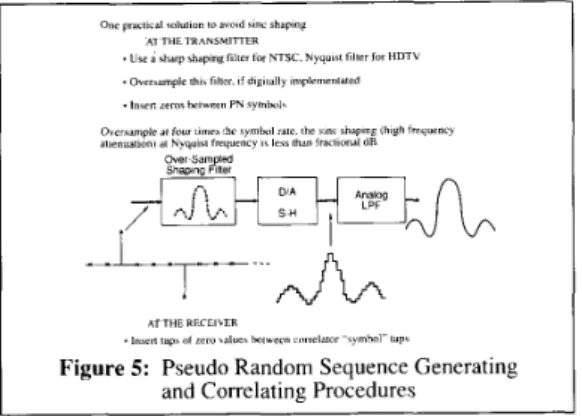
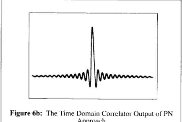
20 0 20 40 0 0 000005 000010 000015 000020 000025 000030 Time (Second1Figure 9: In-Phase Ghosted Training Signal frequency should be used. For an HDTV system, a raised-cosine pulse s h a p i n g filter should be used to avoid intersymbol interference between symbols. It is possible to d o this in the analog d o m a i n . However, f o r accuracy we m i g h t want to implement filter shaping in the digital domain and then convert the digital signal to an analog signal for transmission. In this case, the s a m p l e - a n d - h o l d circuit in a d i g i t a l - t o - a n a l o g ( D / A ) conversion process introduces a step function between any two samples and results in a sin x/x shaping in the frequency domain. To overcome this problem, filter shaping should be operated at a rate several times higher than the symbol rate, and zero values should be inserted between any two discrete PN symbols at the input to the oversampled shaping filter, as shown in Figure 5 . If the oversampling rate is four times higher than the symbol rate, the effect of the sin x/x frequency shaping on the transmitted signal is greatly reduced. The high frequency attenuation on the transmitted signal becomes negligible. At the receiver, for doing d i g i t a l signal p r o c e s s i n g the received signal i s usually oversampled. To avoid sin x/x high frequency attenuation at the correlator operation, the correlator tap coefficients should be properly spaced according to the oversampling rate. If the input signal to the correlator is sampled at twice the symbol rate, the correlator tap coefficients should be spaced by two samples. Conceptually, a null tap is inserted between every two active correlator taps. Figures 6(a) and (b) show the frequency-domain c o r r e l a t o r o u t p u t a n d the t i m e - d o m a i n c o r r e l a t o r o u t p u t ,
2o
1
II li
0 0 000005 000010 000015 000020 000025 0 0 0 0 3 0
Time [Second,
800
I Figure 12a: Create Quiet Zones by Shift-and-Add
IEEE Transactions on Consumer Electronics, Vol. 36, No. 4, NOVEMBER 1990
100 80 60 40 20 0 20 .Signal dirmrccd by 5%. 109. 5% m d 3% ghn%
d -10. I S . 50 and 65 iymhol dclay IaaUani
-60 k
,
I I 10 0 000005 000010 000015 000020 000025 000030
T m e (Second)
Figure 11: Remained Signal After Subtraction, Received by a Stable PI1 TV Receiver
respectively. These can be compared to the results shown in Figures 7(a) and (b) of an ill-designed system where high frequency c o m p o n e n t s are greatly reduced, such that the attenuation is about 13.4 dB at 4.2 MHz.
111. AN ENHANCED NTSC SYSTEM
If a sufficient time span was available, our proposed scheme would repeatedly send the shaped modified PN sequence at the transmitter. Therefore, at the receiver the received sequences could be correlated with its associated response to produce quiet zones for precise multi-path channel response characterization. However, a horizontal synchronization pulse is inserted between any two lines, and it is not possible to send many consecutive PN sequences without interruption. Also, the available bandwidth in the vertical blanking interval is precious. More and more demands for the usage of the VBI are foreseeable. To send repeated sequences is undesirable, if not impossible. As a result, our proposed scheme only involves the insertion of a single PN sequence of 255 symbols transmitted at 7.16 M symbols/second during the vertical blanking interval. In this case, a multi-path delay range of 35.6 p second can be accommodated. At the receiver a new signal is created to mimic the same effect as if repeated sequences were sent at the transmitter. The choice of a
symbol rate of 7.16 M symbols/second is due to a constraint in an NTSC receiver where the standard sampling rate is set at 14.32 MHz. To make it possible for us to design a correlator using only additions in the computation, we have to send a PN sequence at 7.16 M symbols/second which is an integral divisor of the sampling rate at the receiver. Then the tap coefficients can be set to 1 or - 1. When the PN sequence at this symbol rate is shaped for transmission by a low-pass filter with a passband of 4.2 MHz, the overall correlation gain will be reduced by about 2.3 dB. Therefore, the net gain over the BTAs approach is about 21.7 dB. According to a survey by BTA, 92% of ghosts are within a -4 to 26 p second delay range and when extended to -4 to 37 psecond, almost all cases are covered. This generally agrees with what is reported in [3] based on their limited observations in Atlanta, Georgia. While our approach can cover well beyond 92% of ghosts, it falls short by 5.4 pseconds for an almost perfect coverage. Nevertheless, even in the latter case, the picture quality is greatly improved since almost all ghosts are cancelled and only some extremely long ghosts remain on the picture. In Section 3.1, we will propose several ways to extend the ghost delay coverage
L J
-1-
:J-
based on the same principle.
Similar to the BTA’s approach, the transmitted sequence is preceded and succeeded by fixed signals (or at least pair-wise constant between successive repetitions) of duration at least that of the maximum expected multi-path delay. A matching line in a different vertical blanking interval contains a zero pedestal signal in place of the PN sequence, with the same leading and lagging fixed signals. As pointed out before, this can avoid interference from ghosts of the surrounding signals. If the modified PN sequence is placed right after the back porch (or about 2 pseconds after the color burst), about 23 pseconds of a pair-wise fixed signal should be used at the end of the preceding line and about 10 pseconds at the beginning of the succeeding line. If the modified PN sequence is placed right before the front porch (or about 2 pseconds before the horizontal synchronization pulse), about 10 pseconds of a pair-wise fixed signal should be used at the end of the preceding line and about 23 pseconds at the beginning of the succeeding line. Depending on how the VBI lines are used by broadcasters, one placement of the GCR signal could be more favorable than the other one. In Figure 8, we show a comparison between BTAs and our proposed NTSC GCR signals. In this figure, the modified PN sequence is placed right before the front
8000
1
1
G. 40G0il
2000 1/ I 1 1 0Wang, Chao and Saltzberg: Training Signal and Receiver Design for Multi-path Channel Characterization - 801 8000 6000 4000 D 0, 2 2000 0 -2000 0 50 100 150 200 250 300 Sample (T:2)
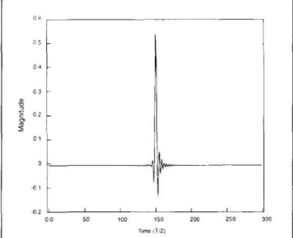
Figure 13: Characterized In-Phase Multi-Path Channel Response
porch. Note that BTA fixes the whole preceding line to obtain a 80
p second interference-free region. (Ghosts with a delay longer than 45 pseconds and shorter than 80 pseconds do not interfere with ghost detection.) A s to be discussed in Section 3.1, our scheme allows us to increase the size of fixed signals in order to significantly increase the ghost delay coverage.
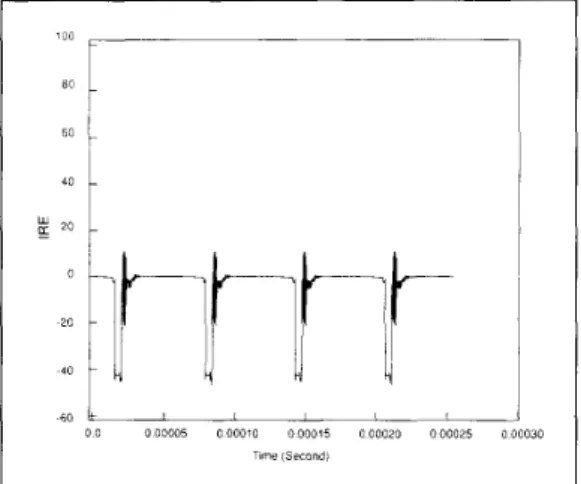
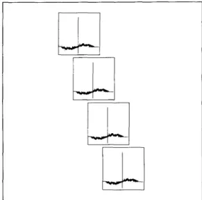
To show another alternative, in the following example, we place the modified PN sequence right after the back porch. At the receiver, matching lines as shown in Figures 9 and I O are subtracted, producing a modified PN sequence and its delayed versions due to multi-path, surrounded by zero signal, as shown in Figure 11. The signals are distorted by 5 % , IO%, 5 % , and 3% ghosts at -10, 25, 50, and 65-symbol delay locations. This new signal is then delayed three times by the length of the sequence, and the delayed sequences added to create four repetitions of the received PN sequence. The result is then fed to a correlator with + I and -1 coefficients. The final correlator output contains four main peaks, at least one pair of which defines a quiet zone during which the multi-path responses can be clearly found. An equivalent approach, but computationally simpler, is to correlate the multi- path distorted PN sequence surrounded by zero signal and to delay the resulting signal at the correlator output three times by the length of the sequence, as shown in Figure 12(a); this new signal is added to create the final output, as shown in Figure 12(b). Figure 12(a) shows that the correlator output associated with a single ghosted modified PN sequence has a peak surrounded by some “sidelobe interferences” due to the transition periods of the correlator operation. Since any two samples of the correlator output separated by N symbols have the same magnitude and an opposite sign, the sidelobe interferences are cancelled after the “shift-and-add” operation. Therefore, the resulting output, as shown in Figure 12(b), has three quiet zones surrounded by sidelobe interferences. In theory, only the second quiet zone is truly quiet since the first and the last quiet zones are interfered by sidelobes of post-cursor ghosts and pre-cursor ghosts, respectively. Figure 13 shows a typical ghosted in-phase response in a single quiet zone. Figure 14 is the in-phase response for a perfect channel. The shift-and-add operation to mimic the transmission of consecutive PN sequences at the receiver would cause about 3 dB noise enhancement. However, when the signal in any two quiet zones are averaged the noise enhancement is about 1 .S dB. This is a penalty paid for our scheme. The net gain over the BTA’s approach is about 20.2 dB. Note that when the discrete modified P N s e q u e n c e is shaped by a low-pass filter with smaller
bandwidth, intersymbol interference results. This causes overshoot and undershoot in magnitude. To avoid excessive overshoot and undershoot, the magnitude of the discrete modified PN symbol is reduced to SO IRE to guarantee that the sending GCR signal does not exceed the transmitter’s linear operation range and the ghosted GCR signal is well within the linear dynamic range of the receiver circuitry. This can be compared to the BTAs wide bar GCR signal which has a sin x/x waveform of about 38 IRE in magnitude before integration and 75 IRE at the leading edge after integration. This is about 2.4 dB in favor of the new approach. Therefore, the net gain of this approach is about 22.6 dB over the BTA’s approach. To further warrant that the received ghosted GCR signal will not be distorted by nonlinearity and that the synchronization pulse separation circuit will not malfunction (accurate synchronization pulse separation before ghost cancelling is needed to determine the GCR signal insertion position), BTA [4] recommended to select the appropriate types of antenna, installation place. height, and direction so as to limit the ghost interference level to be 6 dB down from the direct signal. Further reduction in the GCR signal strength can avoid the possibility of nonlinear distortion in channel characterization. However, this will further reduce the signal-to- noise ratio. Since our scheme provides a significant correlation gain to begin with, we can afford to reduce the GCR signal strength. If the conventional synchronization pulse separation circuit malfunctions, the system fails. In this case, our approach provides a means to achieve precise synchronization using the peak in the real-time correlator output as a reference. If the simplified real-time correlator using only additions is still too complex, an even simpler correlator can be used. This correlator takes sliced signals as binary input and uses exclusive OR logic to match the P N sequence. T h e peak c a n than be used as a synchronization reference. The correlator used for channel characterization can be performed on an off-line basis to further reduce the cost.
Although it might not be needed, our scheme can be further improved by averaging over several 8-field sequences. In 0.25 second, which is still well within the 1.0 second specification of tracking changing ghosts 141, 9 dB improvement in the signal-to- noise can be achieved. Note that for the BTAs approach to obtain the same signal-to-noise ratio it takes about 68 seconds. For areas behind high building and hills the signal is weak. It has been observed that it can take longer than 68 seconds.
Confirming previous results by BTA [4], we also observed that a typical synchronous detector can be affected by phase noise [7].
D B 0 4 O 5
1
0 3 3 2 E 0 2 0 0 1 0 0 1 0 0 50 100 150 200 250 300 Tlme (T!21802 IEEE Transactions on Consumer Electronics, Vol. 36, No. 4, NOVEMBER 1990
1 Figure 15: Spectrum Compatibility HDTV Frame Format
.
First
1 I59 94
Second 1/59 94 Encoded Video sec
*Symbol rate IS about 5.6M symbolslsecond * 127-symbol time span IS about 23 pseconds
Therefore, the accuracy in channel characterization can deteriorate. However, our scheme provides a significant correlation gain so the effect is not severe. It appears as if there were some additional weak ghosts. Those false ghosts have a strength about 32 dB below the direct signal. A picture with those false ghosts will meet target values which are 30 dB below in a weighted measurement (or a subjective evaluation of score 4 based on a CCIR five-step ranking). Since score 4 is perceptible, but not annoying, our scheme allows a receiver to use a cheaper synchronous detector. Even if an ideal synchronous detector is used, the BTA’s approach still has several drawbacks. For example, it provides a prolonged sync pulling duration at the time of power on or channel selection.
Note that for an NTSC system VSB modulation is used. When a ghost has a phase rotation with respect to the direct signal, the phase rotated quadrature component also appears in the inphase correlator output. This might seem to be an interference for channel characterization. In fact, this information is needed if we want to implement a “real” ghost canceller using only the inphase signal as the input, as opposed to a more costly cross-coupled (complex in mathematical sense) ghost canceller using both inphase and quadrature signals as the input. Therefore, only one correlator is used to acquire this complex channel information which includes the inphase channel response and the cross- coupled interference from the quadrature subchannel.
Extending Ghost Delay Coverage
As mentioned above, while our approach can cover well beyond 92% of ghosts, it falls short by 5.4 pseconds for an almost perfect coverage. In this section, several methods that can be used to extend the ghost delay coverage are discussed.
When a long delayed ghost appears in the channel, ambiguity in ghost detection results. For example, a post-cursor ghost delayed by y pseconds , which is longer than the maximum delay coverage, appears in the next quiet zone and is mistaken as a ghost delayed by (y - 35.6) pseconds. Also, a long ghost with a delay slightly shorter than the maximum delay coverage can be mistaken as a pre-cursor ghost. In this case, the multi-path equalizer would not cancel this long delay ghost but instead would create another false ghost. To prevent this from happening, we can change the symbol rate of the PN sequence to accommodate a
larger ghost delay range. For example, a PN sequence of 255
s y m b o l s transmitted at 5.67 M s y m b o l s / s e c o n d would accommodate a ghost delay range of more than 45 pseconds .
Unfortunately, the correlator tap coefficients are not just 1 and - 1. Correlating with the input at a rate of 14.32 MHz requires N multiplications and additions per symbol period to interpolate because of the non-integral ratio between symbol and sample rates.
In the above case, we assume that the “standard’ sampling rate at the receiver (four times of color subcarrier frequency) should not be changed. If we are allowed to change the sampling rate at the receiver to a multiple of 5.67 MHz, such as 17.01 MHz, a simple correlator can still be used.
Note that the leading and trailing sidelobe interferences in Figure 12(b) are deterministic signals and thus, at least in theory, can be eliminated. Also, note that the leading period is not affected by the “shift-and-add” operation. Therefore, only pre-cursor ghosts exist in the leading period. Similarly, only post-cursor ghosts exist in the trailing period. Since almost all pre-cursor ghosts are very strong, most probably they can be detected even with the presence of the sidelobe interference. Even if this is not the case. with some elaboration, the sidelobe interference can be closely reproduced. As one example, the most d a m a g i n g part of the sidelobe interference can be reproduced by convolving the channel response near the first peak with the known sidelobe interference of an ideal channel. Therefore, the leading sidelobe interference can be significantly reduced, so we can easily detect the locations of pre-cursor ghosts. The information can be used to resolve the ambiguity between a long delay post-cursor ghost and a pre- cursor ghost around the second peak in Figure 12(b). This allows channel characterization for pre-cursor ghosts with a delay up to -
35.6 p s e c o n d s . Since post-cursor ghosts longer than the maximum delay coverage do not appear in the first quiet zone, the locations of post-cursor ghosts can be determined. T h e information can be used to identify any long delay ghost in the second quiet zone, which has an absolute delay between 35.6 pseconds and 71.2 pseconds . Note that we assume that ghosts delayed into the second quiet zone do not overlap with the short delay ghosts in their own correct locations and sufficient pair-wise fixed signals are placed before and after the GCR signals. In this case, we can identify ghosts with a delay between -35.6 pseconds and 71.2 pseconds.
Finally, note that if we borrow some ideas from a somewhat more complicated scheme used for SC-HDTV (to be described), the ghost delay range can be extended to -17.8 to 35.6 p second. This requires alternatively sending two PN sequences whose length are 255 and 127, respectively. Line Structure PN1 ot B PN127 Line Structure PN2 of a PN63 01 s PN63 Figure 16
Wang, Chao and Saltzberg: Training Signal and Receiver Design for Multi-path Channel Characterization
1
803
Compare Outpul 01 Combiner During the Frst Training Sequence 10 a Large Threshold and E s f a l s h Oulel Zone
5 For Each Signal Stored m Step 2 Compere l m e to End
01 Quiet Zone with that 01 Each Signal Stared 8nStep 4
OufputAveiage ~ I t h e T w o A m p l i t ~ d e ~ and t h e l m e Betore End 01 Ouel Zone
1 6 7 Bias-Free 4 Correlators
,
4 & Combiner .-) output 8Figure 17: Ghost Ambiguity Resolution Algorithm
Oufpul Amplitude andlime 1r0m Pulse 107 01 Remaimng Signal Stored ~n Step 2
Trade-off Between TV Ghost Cancelling Time And The Usage Of VBI
t o
A concern of many broadcasters is the usage of the VBI resource. VBI is a finite resource and there is an increase in the demand for using VBI for many applications such as Teletext and data transmission. The usage of VBI to transmit the GCR signal is becoming a real concern. Since our new PN approach has a convergence speed that is several hundred times faster than BTAs wide bar GCR signal approach, our new PN approach offers a possibility of reducing the usage of VBI by slightly increasing the TV ghosting cancelling time. For example, the PN training signal can be sent one-tenth as frequently, thereby using one-tenth as much VBI resource, but still offers a speed of convergence that is an order of magnitude faster than BTA's wide bar GCR signal.
OUlput Amplitude and lime from Pulse 209 01
Remaining Signals Sfored in Step 4
As proposed by BTA, in order to provide a wider ghost delay range with limited time span available to the GCR signal, "the subtraction method" is used. For BTAs approach a preceding line should only send pair-wise fixed signals. In our approach with 35.6 psecond ghost delay coverage, the preceding line should have I O p second pair-wise fixed signal and 23 pseconds in the succeeding line. In North America, as authorized by the FCC, line 19 (field 1 and field 2) is dedicated to a fixed vertical interval reference (VIR) signal for automatic color adjustment at the receiver. Line 20 (field 1) is heavily used for channel ID and other information and field 2 carries a testing signal used by the networks. Line 21 (field 1 and field 2 ) sends captioning. Assuming that lines 19-21 cannot be changed for usage and line 18 will be used for broadcasting the GCR signal, BTA's approach requires that line 17 be used to send pair-wise fixed signals. Our approach only requires about 10 pseconds at the end of line 17 to send pair-wise fixed signals, and there are about 18 pseconds in line 18 that can also be used for sending pair-wise fixed signal. Therefore, the effective VBI usage of our approach is less than a line, not to mention the possibility of sending our proposed GCR signal less frequently to significantly reduce the VBI usage. If the ghost delay distribution in a certain area is small (in most locations, it is very probable that ghost delay is less than 26 pseconds ), an individual broadcaster can decide not to impose
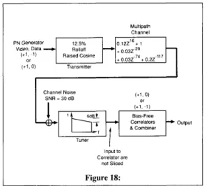
Multipath Channel PN Generator VldeO. Data
I
C y n e l Noise SNR = 30 dB ( + I , 0) or-
I Tuner ''
I
Input to Correlator are not Sliced Figure 18:any constraints on line 17, and our scheme would not be affected. Even if the ghost delay range is more than 36 pseconds and a broadcaster decides not to impose any constraints on line 17, our scheme will only be slightly affected. In this case, the long delayed ghosts from the last 10 p second in the preceding line could corrupt, as noise, the near-by pre-cursor and post-cursor ghosts. Since long delayed ghosts are rare and weak and the near- by ghosts are strong the degradation might be negligible. Therefore, our scheme should perform well without enforcing any constraint on the use of line 17.
Finally, it is also possible to completely eliminate the need of sending pair-wise fixed signals. However, ghosts from the preceding line and signal in the succeeding line will corrupt, as noise, the channel characterization process. It will take many iterations of averaging before precise channel information can be obtained.
Comparison Between T h e BTA's Approach A n d Our Proposed NTSC Approach
Table 1 shows the comparison between the BTAs approach and our proposed NTSC GCR approach
TABLE 1 Comparison
BTA's Proposal Our Proposal 22 6 dB better Against while nnise
Ghost cancelling time Usage of VBI
Tracking airplane nutler Loss of conwntional svnchronution before deghosting
Degrading due to nnchronous detector imperfection Degrading due to non-lmearitv .\gainst interference other than white now
!
__
Fxtreme Slight Not etTectwe Effective
---
Overall complexit)
i
Ghost dela) coverage* The GCR \ignal can be transmitted less frequently to reduce the usage of VBI at * Ah mentioned in Section 3.1, with some elaboration it i s possible for our scheme
a ?mall expense of system convergence.
to extend the ghost delay coverage to -3.5.6 pteconds and 71 2 pteconds.
As reported in [3], the BTA system was unable to correct for ghosts in 7% of their observations, conducted in City Grade service areas. It can be expected that the percentage of failure of the BTA system is higher in remote service areas. Based on the
804 IEEE Transactions on Consumer Electronics, Vol. 36, No. 4, NOVEMBER 1990 140 ,
I
107 lZOt
100c
40 20 0 0 100 200 300 400 500 600lime in Symbol Period
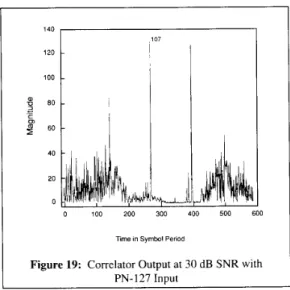
Figure 19: Correlator Output at 30 d B SNR with PN- 127 Input 70 60 50
9
40 c rn9
30-
20 10 0 209 L 0 100 200 300Time in Symbol Period
~
3 500 600
Figure 20: Correlator Output at 30 d B SNR with PN-61 Inuut
comparison made above, it is clear to us that our new approach can greatly improve the system performance and ghost correction coverage. The investments made by customers, broadcasters, chip suppliers, and TV manufacturers can therefore be protected.
IV. A TRAINING TECHNIQUE FOR HDTV The same concept described above can also be used for HDTV applications. However, in most HDTV proposals, av..ilable bandwidth is precious and the amount of time reserved for fixed signals must be kept to a minimum. In this section, we propose an alternative for HDTV applications, if this is desirable. The HDTV format used as an example here is shown in Figure 15.0nly one line of 6 4 ysec duration is used for transmitting the training sequence during each field. Preceding and succeeding lines are used to carry other variable information, so the subtraction scheme outlined above cannot be used. Instead, two different repeated sequences are sent in alternate fields of each frame. Note that an H D T V receiver using Q A M modulation h a s independent inphase and quadrature components, and the equalizer should employ a cross-coupled (complex in mathematical sense) structure. To characterize this complex channel, a PN sequence is sent over either the inphase or quadrature subchannel. Some channel distortion can cause cross-interference between inphase and quadrature components. Therefore, at the receiver two correlators are used to acquire separate inphase and quadrature channel information for use in a complex equalizer. Note that this is different from an NTSC system using VSB where one correlator is used to acquire complex channel information, including the inphase response and the cross-coupled interference from the quadrature subchannel.
The example to be described is capable of characterizing multi- path responses with delays between -4 and 23 ysec., but can clearly be altered to handle other delay ranges. Both sequences are transmitted at a symbol rate of 5.6 MHz., +1 and - 1 in level, shaped as before,and processed at the receiver with a correlator with coefficients of +1 and 0. Another choice is to transmit sequences of +1 and 0 in level, and processed at the receiver with a correlator with coefficients of +1 and -1. The former set of coefficients is illustrated in this paper.
The sequences are shown in Figure 16. The first sequence is of
length 127, repeated twice with partial sequences before and after. The output of its correlator contains two main peaks, but the first 10 y sec. of the interval may not be quiet because of delayed versions of preceding unrelated signals. The remainder of the interval is quiet, but signals appearing here may be either due to post-cursor multi-path delay between 13 and 23 yseconds , or to precursor multi-path.
The second sequence resolves these problems. This sequence is of length 63, repeated five times with additional partial sequences. The last pair of main pulses at the correlator output defines a quiet zone during which a different set of ambiguities exist. In that zone, ghosts due to a delay within 12 yseconds will overlap with post-cursor ghosts delayed from the sequence ahead and with precursor ghosts. However, by comparing the outputs of the two correlators, all ambiguities can be resolved as shown in the flow chart of Figure 17.
A simulated test was run using the channel of Figure 18, which includes noise and an imperfect tuner as well as multi-path. Figure 19 shows the output of the first correlator. The first part of the interval between main peaks is clearly corrupted, but multipath responses are readily extracted from the latter part of the interval, where the noise can be seen to be quite low. The output of the second correlator is shown in Figure 20, where the same multipath s i g n a l s clearly appear. By c o m p a r i n g t h e s e t w o o u t p u t s , a m b i g u i t i e s c a n be resolved a n d t h e c h a n n e l a c c u r a t e l y characterized.
The use of PN training sequences is valuable for more than precise characterization of multi-path. The strong main pulse at the output of the correlator is an excellent signal to be used for synchronization and gain control.
APPENDIX A
V. CONSIDERATIONS OF USING A POLYPHASE
SEQUENCE
Other well-known sequences such as a polyphase sequence [9,10] can also be used to obtain the correlation gain. A polyphase sequence has a frequency response with a equal magnitude values and many different phases which are roots of unity. It has zero autocorrelation between peaks. It has been shown that sequences exist for all lengths. If the length N is odd, an N-phase sequence
Wang, Chao and Saltzberg: Training Signal and Receiver Design for Multi-path Channel Characterization 805
of real values can be constructed; if N is even, 2N phases are needed. For convenience in the discussion, we will refer to these sequences as real polyphase sequences. With a minor extension, we can construct a complex polyphase sequence composed of an i n p h a s e s e q u e n c e a n d a q u a d r a t u r e s e q u e n c e . T h o s e t w o sequences are orthogonal with zero crosscorrelation. In this case the sequence length is doubled. The frequency response of the inphase sequence is constructed by inserting a zero between any two samples of the real polyphase sequence. The frequency response of the quadrature sequence can be constructed in a similar way. The zero values of the two orthogonal sequences are offset by one sample to warrant that the product of the two spectra is zero (disjoint) and therefore, orthogonal. From a time domain point of view, a complex polyphase sequence of length N has an inphase correlation function with two positive peaks of the same magnitude at the (N/2)th sample and the Nth sample, respectively, and a quadrature correlation function with two peaks of different sign and the same magnitude at the (N/2)th sample and the Nth sample, respectively. The other correlation values are zeros. Note that the ghost delay coverage of a complex poly-phase sequence is only half of its length.
For an NTSC system using VSB modulation, a real polyphase sequence can be used. For an HDTV system using QAM with independent inphase and quadrature components ( Q A M is conceptually a complex channel), a complex polyphase sequence of orthogonal components can be used. (We will describe in Section 4 how a real sequence can be used to characterize a complex channel.) A polyphase sequence has nice properties and it might seem to be more attractive than a PN sequence. For example, the length of a real polyphase sequence can be any positive integer, as opposed to a PN sequence where the length needs to be 2n -1, n a positive integer. The frequency response of a polyphase sequence is flat, as opposed to a PN sequence which h a s a s m a l l D C c o m p o n e n t . H o w e v e r , c o r r e l a t i n g with a polyphase sequence requires non-integral tap coefficients. Therefore, it always requires N multiplications and additions in each symbol period. A polyphase sequence has significant n e g a t i v e m a g n i t u d e s which m i g h t i n t e r f e r e with N T S C synchronization pulses and color burst in an existing TV receiver. The correlator associated with a polyphase sequence does not provide a DC blocking effect. For a complex polyphase sequence the ghost delay coverage is only one half of its length. Therefore, it results in degradation for some equalization schemes. Due to the considerations mentioned above, we only deal with the modified PN sequence approach in this paper.
APPENDIX B
VI. THE EFFECT OF HIGH FREQUENCY ATTENUATION
IN GHOST CANCELLATION
Reference [ 11 describes a “forward a l g ~ r i t h m ” ~ which takes the fast Fourier transform (FFT) and inverse FFT of the received reference signal and a “dividing method” to obtain the equalizer tap coefficients. If high frequency attenuation occurs, the tap coefficients are not accurate and the equalizer can’t recover the higher frequency components such as the color signal.
3 The forward algorithm does not imply the use of a FIR filter in the cancellor. In fact, [I] descnbes a FIR (forward) filter to cancel near-by ghosts and a IIR (feedback) filter to cancel far ghosts.
Another method is the “feedback a l g ~ r i t h m ” ~ also described in [ 11. The channel is characterized using the received reference signal in order to obtain the information about where ghosts are located. The LMS (Least-Mean-Squared) adaptive algorithm, which is constrained in the number of tap locations (sparse filter), is then used to fine tune the tap coefficients, with the received reference signal as the input and the original reference signal as the ideal signal. An additional effect of high frequency attenuation is to slow down the speed of convergence of the adaptive LMS algorithm due to the spreading in eigenvalues associated with the input.
It might be worthy of mentioning that the feedback algorithm is much more sensitive to DC offset in the system than the forward algorithm.
There are other filter tap coefficient calculation algorithms [2] which are more suitable for VLSI implementation. They should be used in order to implement a cost-effective ghost cancelling VLSI circuitry.
APPENDIX C
VII. USE OF PN TRAINING SIGNAL FOR OTHER SIGNAL PROCESSING
CO-channel i n t e r f e r e n c e will be a s e r i o u s p r o b l e m f o r simulcasting HDTV and NTSC signals. For example, an HDTV system in this environment experiences strong narrow-band carrier interference from a NTSC channel. The PN approach can provide correlation gain to minimize the effect of this narrow- band interference. This provides several hundred times better narrow-band interference immunity over BTA’s wide bar GCR signal. Ideally, for an HDTV system a fixed comb filter can be used to reduce the NTSC co-channelnarrow-band interference. T h e picture carrier in an N T S C signal can drift by a FCC regulated nominal value, k 1 ~ H Z . ~ If the correlation gain does not p r o v i d e e n o u g h i m m u n i t y f o r very a c c u r a t e c h a n n e l characterization, some type of adaptive noise cancellation technique should be used. An adaptive harmonic (comb) noise canceller [ 1 I ] can be used to mitigate this problem. This adaptive noise canceller can position itself according to the frequency drift in the carrier. However, to properly adapt to a harmonic noise canceller, the main signal should be highly distinguishable in correlation from the narrow-band interference. The PN signal is an excellent candidate for this type of signal processing but BTA’s wide bar GCR signal is not. Our hardware implementation using this adaptive harmonic noise canceller working in conjunction with the correlator shows that when the PN reference signal is corrupted by a narrow-band interference our scheme creates a harmonic notch filter response in the frequency spectrum to cancel this interference. Therefore, it improves the overall performance. There are many more possible signal processing techniques that are applicable to improve the picture quality, and most of them can take advantage of a training signal of the desired correlation property of the PN signal.
4 Similarly. the feedback algorithm does not imply the use of an IIR filter in the canceller.
5 Today’s carriers have a much more stable carrier. The offset is about 100 Hz. Technology I S available to have an even more precise camer with an offset of I Hz.