E L S E V I E R Microelectronic Engineering 41/42 (1998) 125-128 M I C R © E L E C T R O N I C E N G I N E E R I N G T i S i x O y A S A N A B S O R P T I V E S H I F T E R F O R E M B E D D E D P H A S E - S H I F T I N G M A S K I N 2 4 8 N M A N D T H E M O D I F I C A T I O N O F R - T M E T H O D F O R T H E D E T E R M I N A T I O N O F S H I F T E R ' S n A N D k a . . a . • a
Wen-an Loong , Chlh-wel Chen, Ya-hui Chang a, Cheng-mmg Lm , Zheng Cui h and Chien-an Lung c alnstitute of Applied Chemistry, National Chiao Tung University, Hsin-Chu, Taiwan 300, Republic of China bRutherford Appleton Laboratory, Chilton, Didcot, Oxfordshire, OXl 1 0QX, UK
CGroup of Mathematics Education, National I-Lan Institute of Agriculture and Technology, 1-Lan, Taiwan 260, Republic of China
TiSixOy as an absorptive shifter (embedded layer) for attenuated phase-shifting mask (APSM) in 248 nm wavelength is presented. TiSixOy thin film was formed by plasma sputtering of Ti (25-55 W) and Si (200-250 W) under Ar (30 sccm) and oxygen (0.1-0.4 sccm). For required phase shift degree 0 =180 °, calculated thickness dis0 of TiSixOy film is within the range of 87-120 nm depending on its reflectivity R, transmittance T, refractive index n and extinction coefficient k. Taguchi design of experiment has been applied to study the plasma etching selectivity of TiSixOy over APSM's substrate quartz (SIO2), under CI2:NF3=20:30 sccm; 50 W and 60 mtorr, selectivity of 10:1-35:1 was observed. Modifications of reflectivity-transmittance (R-T) method have been developed for the determination of this absorptive shifter's n and k.
1. I n t r o d u c t i o n
We have reported TiNx and TiSix as new embedded materials for APSM [1,2], here we report TiSixOy as another new material suitable for using as an embedded layer for APSM. TiSixOy was formed by plasma sputtering of Ti and Si under Ar and small amount of oxygen. The content of oxygen could manipulate the optical properties of this thin film. By combining the slope method [3] and R-T method [4,5], a modified R-T method which is easy and inexpensive was developed in this report to obtain the n and k of TiSixOy thin film.
2. E x p e r i m e n t a l
The deposition of TiSixOy thin films on substrates of quartz or Si wafer were carried out with an Ion Tech Microvac 450cb sputtering system. The sputtering conditions were as follows: reaction pressure 7.8 mtorr; targets Titanium (Ti) and Silicon (Si); input gas Ar 30 sccm, oxygen 0.1-0.4 sccm; substrate: glass, quartz or Si wafer. For Ti target, DC power 25-55 W, 290V, 0.16 A; for Si target, RF forward 200-250 W, RF reverse 4.2 W, bias -166 V; deposition rate 0.24-0.27 A/sec. Transmittance
0167-9317/98/$19.00 © Elsevier Science B.V. All rights reserved. PII: SO 167-9317(98)00027-6
and reflectivity were taken from a Shimadzu UV- 2501PC double-beam, double-grating UV-VIS spectrometer. Thicknesses were measured from a Dektak 3030 surface profilometer and a Rudolph Research auto EL II ellipsometer. Depth profiles of ions were analyzed by a Cameca IMS-5F Secondary Ion Mass Spectrometer (SIMS) using O: ÷ as ion source under 12.5kV and 3000 mass resolution power. Resistance measurements were performed using a Napson RT-7 resistivity analyzer. Micrographs were taken by a Hitachi S-4000 field emission SEM. Atomic force microscope (AFM) used is Digital Nano Scope 3. The dry etching of TiSixOy and substrate was studied using a Vacutec AB1500S RIE.
3. R e s u l t s a n d D i s c u s s i o n
3.1 D e t e r m i n a t i o n o f n, k
The exact determination of refractive index n of embedded layer is critical for APSM. The methods used are described as follows.
A. Slope Method
The equations used by slope method are listed as follows [3]:
126 W.-a. Loong et al./Microelectronic Engineering 41/42 (1998) 125-128
R=[(n - 1)2+k2]/[(n+ 1 )2+k2] ... eq. 2 dis0 = ~./2(n- 1) ... eq. 3
Where T is transmittance; k:extinction coefficient; ~:wavelength of incident light; d: thickness of thin film; R: reflection of thin film; n: refractive index; d180: thickness of thin film with exactly 180 degree of phase shift of exposure light. The plot of In T (not T %) as a function of film thickness d is linear. From this linearity, the extinction (or absorption) coefficient k is calculated from eq. 1. R% can be calculated as intercept from eq. 1. R% can also be measured directly from an UV-VIS spectrometer equipped with a reflection measurement attachment. The measured R is more reliable than calculated R by our experience. With known R and k, the value of n then could be calculated from eq. 2. With known n, the d~8o could be calculated from eq. 3. However, n obtained from the slope method is not accurate.
B. VASE Method
VASE (variable angle spectroscopic ellipsometer) method measures thin film's ~P and A. The relative equation can be simplified as follows:
p* = tan (W) exp (i 6) = Rp* / Rs*
Where 9" is a complex which indicates the ratio of the complex Fresnel reflection coefficients of Rp* (p- polarized, parallel, in-plane) and Rs* (s-polarized, vertical, out-of-plane); W is related to amplitude ratio of p to s components (0-90°). A is the phase difference between p and s (0-360°). From the data of q-' and A under various angles, the n and k of a thin film can then be calculated from fitted curves. VASE is a good tool for this purpose, however, it is expensive and not generally available with deep uv wavelength extension in most of labs.
C. R-T Method
R-T method [4,5] has much less wavelength limitation as method of VASE. R-T method provides an easy and less expensive alternative. Under the condition of known film thickness d and with measured R% and T% from an UV-VIS spectrometer under 193, 248, 365 nm or other wavelength, the n and k can be found from the intersecting point of plot of contours of constant T% and R% in the n-k plane. However, R% and T% are not monotonic functions o f n and k, there may be more than one intersecting points for the R% and T% contours. Hence, the suitable domain must be chosen to obtain correct n and k of thin film.
D. Our Modified R- T Method
Three modifications to R-T method have been developed. Firstly, a computer program using windows BASIC has been written to do all the necessary calculations. Secondly, value of n generated by slope method was used to to pick up the right domain in this method, hence, speeding up the computation and reducing the data matrix. Thirdly, an approximate correction of measured transmittance (T%) has been applied to the calculation of n and k. Due to the complicate nature of light scattering, straying and reflection on the rough surface of absorptive shifter, the real T% is little higher than measured T% as illustrated in Fig. 1 and should be used in the R-T method. The approximate correction of measured T% is based on the refractive indexes of quartz substrate and absorptive shifter [6].
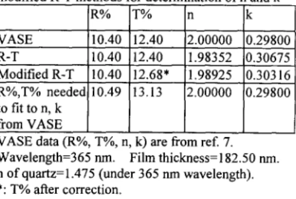
The comparisons of VASE, R-T and modified R- T methods for determination of n and k under i-line (365 rim) from sample TS-09 [7] were summarized in Table 1. After approximate correction, corrected T% (12.68) instead of measured Y % (12.40) was used and both the calculated n, k are closer to values obtained from VASE. The R-T method without our modification resulted in much larger deviation from the results by VASE. Measured R% is a total reflection by using A1203 as external standard. In theory, there is no need to correct the measured R%. However, both corrections of R% (10.49) and T% (13.13) are needed for R-T method in order to fit to the n, k values obtained from VASE. Exact correction of T% and R% needs further and extensive study and is beyond the scope of this report.
Table 1. The Comparisons of VASE, R-T and modified R-T methods for determination o f n and k
R% T% n k VASE 10.40 12.40 !2.00000 0.29800 R-T 10.40 12.40 1.98352 0.30675 ModifiedR-T 10.40 12.68' 1.98925 0.30316 R%,T% needed 10.49 13.13 2.00000 0.29800 to fit to n, k from VASE
VASE data (R%, T%, n, k) are from ref. 7. Wavelength=365 nrn. Film thickness=182.50 nm. n ofquartz=l.475 (under 365 nrn wavelength). *: T% after correction.
W.-a. Loong et al./Microelectronic Engineering 41/42 (1998) 125-128 127 I inc
-.~/
l
Io Reference Beamvjline nlair 24T
1 0¸9
. , Q .
22 ... •
~.~
o7
n 2 i i . • 0,5 k ID 1; ~ / " a r n quartz 1.8 " - - : . I' / ~ N n3 1.6 , , o. Io {) absorptive 0 o. 1 o.2 o.3 o.a
- - shifter O x y g e n F l o w (sccm)
I ( e m b e d d e d Sample layer)
B e a m Fig. 2 The effect of oxygen flow on n and k of TiSixOy film under Ti 40W, Si 250W, Ar 30 sccm.
n I' 0 = I i n c [ 1 - ( n 2 - n 3)21 n 2 + n 3
__I
24 f'i"i ...
]
" - ~ ~ ! ~ ... 1 '09 M e a s u r e d T % = i0 x 1 0 0 % 23 . . . I . . . • 08f
1
Real T % = i' 0 x 100 % n 2 2 0.6°7k
i' o < lo * * o5 2 I ' ' 04 Real T % > Measured T % 25 4O 55 7OFig. 1 Illustration of approximate correction of absorptive shifter's transmittance (T%) on measured T% obtained from double beams uv spectrometer and correction equations used.
~L
~.n.
- - o - - k r - -tl
2 1 7 ~ ' 0.9 - - . . . .I
. . o . . . 0.8 1 2 . J • . . . 0.7K
1 9 0.6 1 8 0.5 150 2 0 0 250 300 Si P o w e r ( W )Fig. 4 The effect of power of Si target on n and k of TiSixOy film under Ti 40 W, Ar/O2=30/0.1 sccm.
Yi P o w e r ( W )
Fig. 3 The effect of power of Ti target on n and k of TiSixOy film under Si 250 W, Ar/O2=30/0.1 sccm.
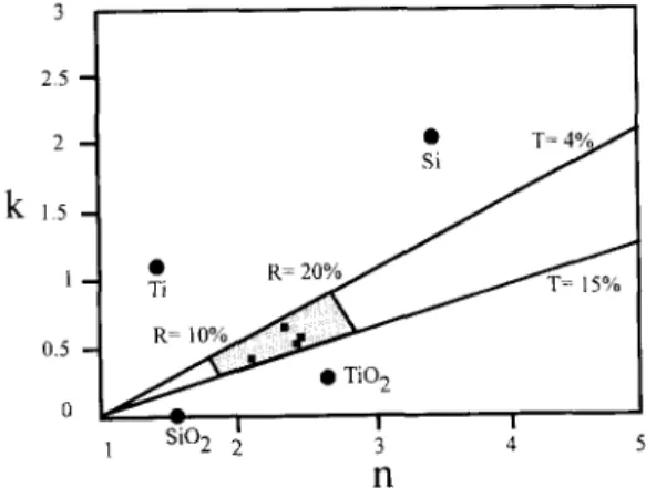
3 2.5 t 2 -- k 1 . 5 - 1 - 0.5 o • T - 4 % j , I J ~ . , , ~ " - • TiO 2 | I I 1 ~ O 2 2 3 4 5 n
Fig. 5 The n, k plane of TiSixOy film under 248 nm. Four black squares are data from this study.
128 W.-a. Loong et al. / Microelectronic Engineering 41/42 (1998) 125-128
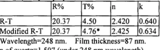
248 nm using modified R-T method, an example was shown in Table 2. n obtained from R-T method was used for the correction of T%. Unfortunately, there is no reliable VASE data to compare with. R% was not corrected.
Table 2. Comparisons of R-T and modified R-T methods for determination of n and k of one of TiSixO v samples ~ared
R% 1"% n Ik
R-T 20.37 4.50 2.420 0.640
Modified R-T 20.37 4.76* 2.425 ~).634 Wavelength=248 nm. Film thickness=87 nm. n of quartz=1.507 (under 248 nm wavelength). *: T% after correction.
3.2 Optical and Physical properties
TiSixOy thin film was formed by plasma sputtering of Ti (25-55 W) and Si (200-250 W) under Ar (30 sccm) and oxygen (0.1-0.4 sccm). For required phase shift degree 0 =180 °, calculated thickness dis0 of TiSixOy film is within the range of 87-120 nm depending on sputtering conditions and its reflectivity R, transmittance T, refractive index n and extinction coefficient k.
For required phase shift degree 0 =180 ° , calculated thickness d from one of the TiSixOy samples prepared is 88.2 nm, and corrected transmittance T% under 248 nm wavelength at this thickness is 4.76 % which is within the useful range for APSM. n 2.425 and k 0.634 were calculated from modified R-T method for this sample.
The oxygen content in TiSixOy film is critical as shown in Fig. 2. The increasing of oxygen content, will decrease the R%, n and k in 248 nm. The transmittance T% at visible wavelength (632.8, 532, 488 run) for optical alignment is 40-50%, suitable for optical alignment if oxygen flow was kept in 0.1-0.2 sccm. Oxygen flow higher than 0.3-0.4 sccm, the T% at visible wavelength will rise to 60-70%, no longer suitable for optical alignment.
TiSixOy films have resistivity (specific resistance) p in the range of 2.4-3.9 f~-cm. It has a good resistance to strong acid and base. By the irradiation of 248 nm deep ultraviolet light for a long time, it's T% increased and R% decreased a little.
The effect of sputtering power of Ti target on n and k was shown in Fig. 3. With higher power, oxidation of Ti occurred, n decreased and k increased. The effect of sputtering power of Si target
on n and k was shown in Fig. 4. With higher power, no oxidation of Si occurred in this case, both n and k increased. The n, k plane of TiSixOy was shown in Fig. 5 which including the window suitable as embedded material in 248 nm. By adjusting the sputtering conditions, the optical properties of TiSixOy could be kept inside this window. The depth profiles of ions of TiSixOy analyzed by SIMS indicated the presence of Ti, Si and O. However, since standard TiSixOy sample is not available; and it is quite difficult for taking RBS spectrum for a thin TiSixOy film on quartz or wafer, the exact composition of TiSi~Oy film was not determined.
3.3 Etching Selectivity
Taguchi method of design of experiment has been applied to study the reactive ion etching selectivity of TiSixOy over APSM's substrate quartz (SiO2). Under C12:NF3=20:30 sccm; 50 W and 60 mtorr, selectivity of 10:1-35:1 was observed from different samples. The roughness of thin films after etching observed by AFM and SEM is satisfactory and it's grain sizes are quite uniform.
4. Conclusions
TiSixOy has low transmittance (<50%) to visible light, optical alignment is possible. It also has small specific resistance, high resistant to strong and hot acid and base, good etching selectivity over SIO2, no need of etching stop layer, therefore, has the potential as embedded material for the fabrication of APSM.
Acknowledgment
This work was supported by the NSC of ROC.
References:
[1] W. A. Loong, T. C. Chen and J. C. Tseng, Microelectronic Engineering, 30, 157 (1996). [2] W. A. Loong, T. C. Chen and J. C. Tseng, and S.
L. Shy, SPIE, 2726, 524 (1996).
[3] K. K. Shih and D. B. Dove, J. Vac. Sci. Technol., B12(1), 32 (1994).
[4] T. C. Paulic, Applied Optics, 25(4), 562 (1986). [5] Z. Cui and P. D. Prewett, Microelectronic
Engineering, 30, 145 (1996).
[6] E. Hecht and A. Zajac, "Optics", McGraw Hill, New York, 1974.