Pseudo-Banyan Optical WDM Packet
Switching System With
Near-Optimal Packet Scheduling
Maria C. Yuang, Po-Lung Tien, and Shih-Hsuan Lin
Abstract—We present a novel pseudo-Banyan opti-cal packet switching system (SBOPSS) for optiopti-cal wavelength division multiplexing (WDM) networks. The system includes a group of pseudo-Banyan space switches together with single-stage downsized fiber-delay-line-based optical buffers. SBOPSS is scalable, with the result that each pseudo-Banyan space switch performs packet switching only for a cluster of wave-lengths. The downsized optical buffers that are shared by output ports via the use of a small number of internal wavelengths result in efficient reduction in packet loss. Essentially, SBOPSS employs a packet scheduling algorithm, referred to as the parallel and incremental packet scheduler (PIPS). Given a set of newly arriving packets per time slot, PIPS deter-mines a maximum number of valid paths (packets) to be scheduled with the current buffers’ state taken into account. The algorithm aims at maximizing the system throughput subject to satisfying three con-straints, which are switch-contention free, buffer-contention free, and sequential delivery. Signifi-cantly, we prove that PIPS is incremental in the sense that the computed-path sets are monotonically non-decreasing over time. We then propose a hardware parallel system architecture for the implementation of PIPS. As is shown, PIPS achieves a near-optimal so-lution with an exceptionally low computational com-plexity, O„円P円Ãlog2„NMW……, where P is the newly-arriving-packet set, N the number of input ports, and M and W the numbers of internal and external wave-lengths, respectively. From simulation results that pit the PIPS algorithm against four other algorithms, we show that PIPS outperforms these algorithms on both system throughput and computational complexity.
Index Terms—Optical packet switching (OPS); wavelength division multiplexing (WDM); fiber delay line (FDL); Banyan network; packet scheduling.
I. INTRODUCTION
O
ptical wavelength division multiplexing (WDM) has been shown to be successful in providing vir-tually unlimited bandwidth to support an ever-increasing amount of traffic for future optical net-works. Future optical networks, especially the metro and local networks, are expected to flexibly and cost-effectively satisfy a wide range of applications having time-varying and high bandwidth demands and strin-gent delay requirements. Such facts result in the need to exploit the optical packet-switching (OPS) [1,2] paradigm that takes advantage of efficient sharing of wavelength channels among multiple connections. Notice that there still exist technological limitations in OPS, such as optical random access memory (RAM) and optical signal processing. Thus, the OPS system we study in this paper employs fiber-delay-line (FDL)-based optical buffers, and almost-all-optical switches in which the control header is processed electronically while the packet payloads remain transported in the optical domain.A general OPS system consists of three basic com-ponents that are crucial to the performance and economy of the system. They are the space switch, the optical buffer, and the wavelength converter [3]. First, the space switches can be categorized into having non-blocking, rearrangeable, or blocking architectures [4]. Traditionally, the nonblocking and rearrangeable switches are mostly used for electronic circuit switch-ing systems. The nonblockswitch-ing switches, such as the crossbar matrix network and Cantor network, can al-ways construct a new connection between the input and the output ports without altering other connec-tions already in the switches. However, the nonblock-ing switches are nonscalable and economically unfea-sible in the optical domain. On the other hand, the rearrangeable switches, such as a Benes network, route new input–output connections by rearranging Manuscript received November 28, 2008; revised March 30, 2009;
accepted May 3, 2009; published July 28, 2009共Doc. ID 112926兲. M. C. Yuang (e-mail: mcyuang@csie.nctu.edu.tw) and S.-H. Lin are with the Department of Computer Science and Information Engineering, National Chiao Tung University, Taiwan .
P.-L. Tien is with the Department of Communication Engineering, National Chiao Tung University, Taiwan.
Digital Object Identifier 10.1364/JOCN.1.0000B1
all other existing connections in the switches. These rearrangeable switches are more scalable than their nonblocking counterparts, but they nevertheless re-quire a more complicated scheduling (or rearranging) algorithm, which causes the switch processing to slow down. The last category, blocking switches, enables self-routing and requires the least number of switch-ing elements among the three categories. Hence, it is the most scalable and most economic class. The price paid, however, is internal contention (blocking) when two packets attempt to access the same internal link in the switch.
Most work done on OPS systems has considered only the nonblocking space switch architecture. The problem to be resolved for such OPS systems is solely the output contentions that are caused if two packets are destined for the same destination. Because of the exceedingly high cost of fast optical switches (and switching elements), we consider the blocking Banyan space switch a promising candidate for future optical networks. To resolve the internal contention problem [4,5] in the electronic domain, numerous methods have been proposed. The most prevailing method, called the buffered Banyan switch, queues contending packets at the input ports through using RAM-based buffers. Such a buffering strategy becomes impracti-cal in the optiimpracti-cal domain. The main goal of the paper is to incorporate a Banyan-like switch architecture to-gether with a fast and high-throughput packet sched-uling algorithm to resolve internal and output conten-tions.
The second component of optical systems, namely, the optical FDL-based buffer, has been successfully applied to resolving contentions in the time dimension under various buffering strategies. Similar to that of electronic switches, the buffering strategy [5] can be categorized into input buffering, output buffering, and shared buffering. While input (output) buffering has a separate buffer for each input (output) port, the shared buffering allows buffers to be shared among multiple inputs and/or outputs. As mentioned previ-ously, because of the lack of RAM-based optical buff-ers, the FDL is currently the only viable buffering means for optical networks. There are two FDL buff-ering structures: feedback or feed-forward [6]. The feedback structure can support dynamic buffering du-rations but at the expense of additional hardware to maintain signal quality [7–9]. By contrast, the feed-forward FDLs support only fixed buffering durations [10,11] but ensure better signal quality. Thus, the feed-forward structure is generally preferred over the feedback-based counterpart.
The third optical-system component, namely, the tunable optical wavelength converter (TOWC), offers an alternative to contention resolution in the space (wavelength) dimension. TOWCs can be realized by
three key methods: four-wave mixing (FWM) [12], cross-gain modulation (XGM) [13], and cross-phase modulation (XPM) [14]. These methods all have differ-ent merits. However, it is worth noting that FWM is particularly attractive due to its being able to convert a group of wavelengths simultaneously and because it is transparent to the modulation format and data rate. Because the use of TOWCs imposes a high cost penalty on OPS systems, much investigation has been carried out to alleviate the cost problem. Some work [15,16] proposes the sharing of a number of wave-length converters, since not all incoming packets re-quire wavelength tuning simultaneously. Other stud-ies have considered more cost-efficient limited-range TOWCs [17,18]. Much work focuses on the combina-tional use of these two ideas to build more economical systems [19–21].
In this paper, we propose a novel pseudo-Banyan optical packet switching system (SBOPSS). The sys-tem includes a group of pseudo-Banyan space switches (PBSs) together with single-stage downsized feed-forward FDL optical buffers. Each PBS is a pseudo-Banyan switch that is of Banyan structure but made from unconventional two-by-two switching ele-ments. Besides traditional cross and bar options, each switching element allows the merging of two packets in two different wavelengths from two inputs to the same output. Moreover, each PBS performs packet switching only for a cluster of wavelengths, yielding a highly scalable system. The economic use of down-sized FDL buffers that are applied on the basis of out-put and shared buffering strategies, as will be shown, results in efficient improvement in system through-put.
Essentially, SBOPSS employs a packet scheduling algorithm, referred to as the parallel and incremental packet scheduler (PIPS). Given a set of newly arriving packets per time slot, PIPS determines a maximum number of valid paths (packets) to be scheduled with the current buffers’ state taken into account. The al-gorithm aims at maximizing the system throughput subject to satisfying three constraints, which are switch-contention free, buffer-contention free, and se-quential delivery. Significantly, we prove that PIPS is incremental, as it is named, in the sense that the computed-path sets are monotonically nondecreasing throughout each time slot. We further propose a hard-ware parallel system architecture for the implementa-tion of PIPS. As will be shown, PIPS achieves a near-optimal solution with an exceptionally low computational complexity, O共兩P兩⫻log2共NMW兲兲, where
P is the newly-arriving-packet set, N the number of
input ports, and M and W the numbers of internal and external wavelengths, respectively. From simulation results that pit the PIPS algorithm against four other
algorithms, we show that PIPS outperforms these al-gorithms on both system throughput and computa-tional complexity.
The remainder of this paper is organized as follows. In SectionII, we present the architecture of SBOPSS. In SectionIII, we describe the PIPS algorithm and for-mally prove the incremental property of the algo-rithm. In SectionIV, we propose the hardware parallel system architecture and derive the computational complexity. Experimental results are then shown in Section V. In Section VI, we then draw comparisons between SBOPSS and several optical space switch structures with respect to hardware cost and signal quality. Finally, concluding remarks are given in Sec-tionVII.
II. SBOPSS—SYSTEMARCHITECTURE
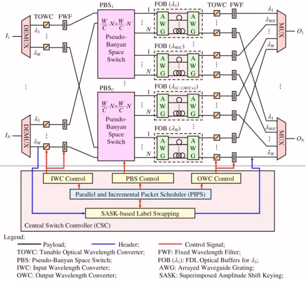
SBOPSS consists of two subsystems (see Fig.1): the optical switching subsystem for optical switching of payloads, and the central switch controller (CSC) for
electronic processing of headers. It is a synchronous system that supports fixed-size packets. Packet head-ers carry the label information and are superimposed-amplitude-shift-keying (SASK) modulated [22] with their payloads. While packet headers are electroni-cally processed by the central switch controller, the payloads travel within the switching subsystem all optically.
The optical switching subsystem consists of four sections: input, space switch, output buffer, and out-put sections. In the inout-put section, there are N inout-put fibers, each carrying W wavelengths, and N⫻W TOWCs. After DEMUX, each TOWC converts the in-put wavelength to an internal wavelength that is as-sociated with a free position in the output buffer for the packet. However, if the system is full, a dump wavelength is converted and the packet is dropped by the filter.
In the space-switch section, there are C PBSs for C wavelength clusters, respectively, where C is the total number of clusters in the system. More specifically,
the kth PBS, i.e., PBSk, accommodates W / C wave-lengths ranging from共k−1兲W/C+1tokW/Cfor each of the
N fibers. This wavelength clustering reduces the size
of each PBS to a scalable N共W/C兲⫻N共W/C兲. Within each PBS, say of size m⫻m, there are 共m/2兲⫻log2m
two-by-two switching elements, each of which can be constructed by four semiconductor optical amplifiers [23]. Each semiconductor optical amplifier can be con-sidered to be an ON–OFF switch to select or unselect the packet, thus forming four different switching de-cisions, namely, cross, bar, and two merging options. Specifically, the merging option allows two packets with different wavelengths to be switched from two in-put ports to the same outin-put port. These two packets ultimately will depart from the system through the same output wavelength and fiber, after receiving dif-ferent delays. Moreover, like Banyan switches, the PBS maintains the self-routing property that allows packets to be uniquely switched according to their out-put port共N兲 and assigned output wavelength 共W/C兲.
The output-buffer section contains W FDL optical buffers (FOBs) for W wavelengths, respectively. Each FOB is shared by all output ports. An FOB is com-posed of a pair of arrayed waveguide gratings and D optical FDLs connecting the arrayed waveguide grat-ings, resulting in a total of B buffer positions, where
B =共D−1兲⫻M, and M is the number of internal
wave-lengths. It is worth noting that a packet entering the FOB at the ith input port will exit the buffer from the
ith output port after receiving a certain delay time
de-termined by the internal wavelength [11]. Thus, for any FOB, an internal wavelength of a packet uniquely determines the delay received by the packet. Finally, in the output section, there are N⫻W FWM-based TOWCs and N output fibers, each carrying W wave-lengths. Because a FWM-based wavelength converter is used that is capable of converting multiple wave-lengths simultaneously, SBOPSS can support the pre-emption of a low-priority packet by a later-arriving high-priority packet [23], which is beyond the main scope of this paper.
In the central switch controller subsystem, headers of simultaneous arriving packets are first superimposed-amplitude-shift-keying-based demodu-lated [22] and received. Their labels are passed to the packet scheduler, PIPS. Serving as the brain of SBOPSS, PIPS determines for each packet the des-tined wavelength and the delay, aiming at maximizing the system utilization subject to satisfying three con-straints. They are switch-contention free, buffer-contention free, and sequential delivery. To avoid am-biguity, we use the term “switch contention” to refer to internal contention throughout the rest of the paper. That means, switch contention occurs when more than one packet carried by the same wavelength at-tempts to pass through the same link within the PBS.
Buffer contention occurs when more than one packet competes for the same FOB position. Notice that, in SBOPSS, packets that are blocked in the PBS or fail to obtain an available FOB position will be inevitably dropped. In the next section, we present the PIPS al-gorithm in detail and formally prove its incremental property.
III. PARALLEL ANDINCREMENTALPACKETSCHEDULER
A. Definitions and Notation
Before delving into the details of the PIPS algo-rithm, we first give notation and definitions that are used throughout the paper. Because packet schedul-ing for different clusters is completely independent, below we discuss the scheduling problem for the sys-tem with one cluster. Let N denote the number of input–output fibers; W the number of input–output external wavelengths (1
I
toWI in the input fiber and 1
Oto W
Oin the output fiber); M the number of internal wavelengths (1 to M); FOBi the optical buffer for wavelength i, where i = 1 . . . W; and D the number of delay lines (including no delay) within each FOB. Each newly-arriving-packet header is associated with the triplicity information (Ii,jI, Ok), where Iiis the in-put fiber,jIis the input external wavelength, and Ok is the output fiber. At the beginning of each time slot, the headers of all newly arriving packets form a header set, P =兵pn兩pn=共Ii,jI, Ok兲n; 1艋n艋兩P兩;1艋i 艋N;1艋j艋W;1艋k艋N其.
To perform packet scheduling, the PIPS algorithm requires the constant update of the FOB states. The state of FOBi is represented by an N⫻D matrix, de-noted FSTATi关Oa, FDLb兴, i=1...W, where each row Oa 共a=1...N兲 corresponds to an input–output port of the FOB, and each column FDLb 共b=0...D−1兲 corre-sponds to a delay line in the FOB. Each entry of the matrix is set to 1 if the corresponding buffer position is occupied and 0 otherwise. Notice that the fact that packets move forward in the delay line after each time slot has elapsed is associated with the left shift of the entries of the matrix.
Definition 1. A valid path for a packet with header (Ii,j I, O k), denoted (Ii,j I, O k,x O, y), is a route within the system that starts from an input port (Ii,jI) of the PBS, through the output port (Ok,xO) of the PBS, to an inlet of an FOB forxO, to a y-corresponded delay line, and finally to the FOB outlet, which is free from being in contention with any packets currently in the buffer, i.e., FSTATx共Ok, FDL共共y−k+M兲mod M兲兲=0.
Definition 2. A sound-path set for a group of newly arriving packets is a set of valid paths Q
⬘
=兵qm兩qm=共Ii,jI, Ok,xO,y兲m; 1艋m艋兩P兩;1艋i艋N;1艋j 艋W;1艋k艋N;1艋x艋W;1艋y艋M其 that satisfies thefollowing three constraints: (C1) all paths in the set are mutually switch- and buffer-contention free; (C2) all packets to which the sound-path set corresponds are buffer-contention free from the packets currently in the buffer; and (C3) the packets belonging to the same connection are sequential-delivery guaranteed.
Notice that a packet may have many valid paths as-sociated with paths lending different delays. Finally, the packet-scheduling problem is formally defined as follows.
Packet-Scheduling Problem Definition. Con-sider a number of simultaneously arriving packets, with the header set P =兵pn兩pn=共Ii,jI, Ok兲n; 1艋n 艋兩P兩;1艋i艋N;1艋j艋W;1艋k艋N其, without any computation-time constraint. The packet-scheduling
problem is to find the largest set of valid paths, referred to as the target sound-path set Q =兵qm兩qm=共Ii,jI, Ok,xO,y兲m; 1艋m艋兩P兩;1艋i艋N;1艋j 艋W;1艋k艋N;1艋x艋W;1艋y艋M其, for a maximal number of packets to be scheduled to simultaneously enter the system. Given a time constraint,
T, the packet-scheduling problem is to obtain within
time T the largest possible sound-path set, referred to as the transient sound-path set Q共T兲 =兵qm兩qm=共Ii,jI, Ok,xO,y兲m; 1艋m艋兩P兩;1艋i艋N;1艋j 艋W;1艋k艋N;1艋x艋W;1艋y艋M其.
A packet will be discarded if its valid path is not in-cluded in the target or transient sound-path set. A dis-carded packet is converted to wavelength0, which in
turn will be discarded through a filter before entering the PBS.
B. PIPS Algorithm
The packet-scheduling problem can be proved to be
NP-complete. In this sequel, we present our PIPS
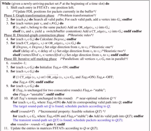
heu-ristic algorithm that finds a near-optimal solution or incrementally returns a feasible solution within a given time constraint. As shown in Fig.2, the PIPS al-gorithm operates in three phases—the graph transfor-mation, directed-graph construction, and iterative self-marking phases—on a slot basis. In the first
phase, the algorithm transforms the packet-scheduling problem into a graph problem according to the following rule. Consider all valid paths for all newly-arriving packets: for each valid path (Ii,jI, Ok, xO, y), a vertex, v共Ii,j
I,O k,x
O,
y兲, is created and drawn
into the undirected graph Gu. Afterward, an edge, CTគedge共v, v兲, is drawn between two vertices vand
vif their corresponding valid paths are in (switch or buffer) contention with each other. Notice that, al-though each packet may have more than one valid path, there is at most one valid path for each packet to be included in any sound-path set. Hence, a special edge, ORគedge共v, v兲, is drawn between two vertices if their corresponding valid paths belong to the same packet, i.e., share the same IiandjI, but using differ-ent delays and/or external wavelengths. The packet-scheduling problem thus becomes finding a maximal set of disconnected vertices in Gu without edges con-necting any two of them.
In the second phase, the algorithm converts the un-directed graph Gu into a directed graph Gd with the edge directions assigned based on two searching heu-ristics in an attempt to maximize the sound-path set. The heuristics provide guidelines based on the Degree of a vertex, which is defined to be the total number of CTគedges (but not ORគedges) connecting to the vertex. Notice that the higher the degree of a vertex, the more paths the vertex (path) is in contention with; the longer the FDL delay of a vertex, the more system re-sources (buffers) are occupied, resulting in a greater possibility that the future arriving packets are blocked. That is, for the edge assigning process, lower-degree vertices are preferred because they contend with fewer vertices (paths), and shorter-delay vertices (paths) are preferred because they leave the system and release resources more quickly. Ultimately, the two heuristics are (Heuristic 1) assigning the edge di-rections from the lower-degree to higher-degree verti-ces and (Heuristic 2) assigning the edge directions from the shorter-delay to longer-delay vertices. In es-sence, Heuristic 1 takes precedence over Heuristic 2.
In the last iterative self-marking phase, each vertex in graph Gditeratively updates the status (Tag) by se-lecting or desese-lecting itself according to the status of its neighboring vertices on a round basis. All vertices are initially marked Tag= ON as being selected. In each round for any vertex, say v, if there exists one neighboring vertex that has an edge directing to ver-tex v and is selected 共Tag=ON兲, vertex v must dese-lect itself共Tagv= OFF兲 to prevent potential contention. Otherwise, vertex v will select itself 共Tagv= ON兲. Es-sentially, as asserted by Theorem 1 (next subsection) for proving the incremental property, if the status of a vertex remains unchanged for two consecutive rounds (the vertex is said to be stable), the status of the ver-tex will no longer be changed. The iteration stops
ei-ther when the status of all vertices remains un-changed within the entire round by the end of a slot time or the requested time constraint共T兲 expires. In the former case, the target sound-path set Q is given as the set of valid paths for the selected vertices. In the latter case, the transient sound-path set Q共T兲 is given as the set of valid paths for the vertices that are selected and stable.
C. Incremental Property
In Theorem 1, we first assert and prove that a ver-tex’s status will no longer change once it is stable. Ac-cordingly, the incremental property is then given and proved in Theorem 2.
Lemma 1. The directed graph, Gd, does not contain
any cycles.
Proof. In the directed-graph construction phase, since Heuristic 1 takes precedence over Heuristic 2, all vertices of Gdare sorted in an absolute order after the two heuristic rules are applied. (Notice that if the vertices have the same degree and delay, they are sorted by the designated ID, as described in the algo-rithm in Fig.2). Accordingly, all edges are directed in the same direction, allowing the Lemma to hold.
Theorem 1. If the status (Tag) of a vertex remains unchanged for two consecutive rounds in the iterative self-marking phase, i.e., the vertex is stable, it will not change in the following iteration rounds.
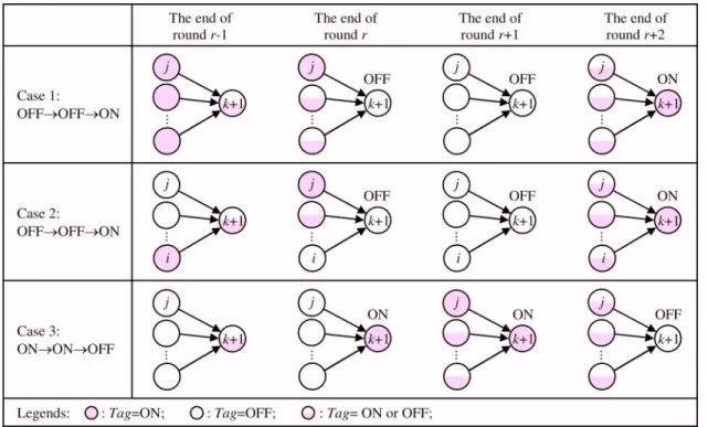
Proof. The proof is performed via mathematical in-duction on the number of vertices in the directed graph Gd. Assume that V is the vertex set of Gd. The basic condition states that the theorem holds for 兩V兩 = 1. If the theorem also holds for 兩V兩=k, we are to prove that the theorem holds for 兩V兩=k+1. Without loss of generality, vk+1is chosen as the vertex that only has inward edges. By Lemma 1, the vertex must exist. Also due to the inductive assumption, vertices v1⬃vk must obey this theorem because the vertex vk+1 will not influence them obviously. Therefore, the proof can be completed by proving that Tagk+1does not produce traces OFF→OFF→ON and ON→ON→OFF during the iterative self-marking phase.
Part 1: First, we show that Tagk+1 will never pro-duce a trace of OFF→OFF→ON. By contradiction, assume that Tagk+1 does indeed produce the trace OFF→OFF→ON from iteration round r to r+2. In this case, there are only two possibilities that can re-alize such a trace, which are illustrated as Case 1 and Case 2 in Fig. 3. That is, for making Tagk+1= OFF in round r, at the end of round r − 1, there must be at least one vertex whose Tag is ON. The main difference between Case 1 and Case 2 is that there exists a non-empty set of vertices that direct to vk+1 with Tag = OFF in Case 2, whereas all vertices are of status ON in Case 1.
Case 1.
1. Round r − 1: assume that Tagk+1= ON or OFF ar-bitrarily, and Tag= ON for every vertex with an edge directing to vk+1. This will imply Tagk+1 = OFF in round r.
2. Round r: to keep Tagk+1= OFF in the next round,
r + 1, there must be a vertex, say vj in Fig.3, di-recting to vk+1, and Tagj is set to ON within this round.
3. Round r + 1: set Tagk+1= OFF because Tagj= ON at the end of round r. To have Tagk+1= ON in the next round, r + 2, all vertices directing to vk+1 must set Tag to OFF within round r + 1.
4. Round r + 2: set Tagk+1= ON because all Tags di-recting to vk+1 are OFF at the end of round r + 1. Now, a contradiction occurs because vertex vj experi-ences a Tagj trace of ON→ON→OFF from iteration round r − 1 to r + 1, violating the inductive assumption we made in the proof.
Case 2.
1. Round r − 1: assume that Tagk+1= ON or OFF ar-bitrarily. There must be a nonempty set of verti-ces with edges directing to vk+1 and Tag= ON, which trigger Tagk+1= OFF in round r. For sim-plicity, in the sequel (and in Fig.3), our illustra-tion includes only one vertex共vi兲 in this set. 2. Round r: in this round, vertex vimust change its
Tag to OFF. Otherwise, it becomes stable by the
inductive hypothesis, and the stability makes it-self remain Tagi= ON in the following rounds; thus Tagk+1 can never be set to ON in round r + 2. However, since it must hold that Tagk+1
= OFF in round r + 1, there must be a vertex (say vertex vj in Fig.3) that was OFF at the end of round r − 1 but is updated to ON in this round. (Note that a situation of having no such vertex is what Case 1 discusses.)
3. Round r + 1: set Tagk+1= OFF since Tagj= ON at the end of round r. In this round, the Tag of each vertex directing to vk+1must be changed to OFF to allow Tagk+1= ON in round r + 2.
4. Round r + 2: set Tagk+1= ON because all Tags di-recting to vk+1are OFF at the end of round r + 1. Now, by the inductive hypothesis made in the proof, all vertices that are unstable (except vk+1) must have the Tag switched continuously between OFF and ON. Recall that all vertices belonging to Gd are initialized with Tag= ON. Thereby, the unstable vertices must have their Tags changed in a synchronous manner. A contradiction occurs, since vi and vj are unstable but with different Tag values at the end of round r − 1. Combining Case 1 and Case 2, we have proved that
Tagk+1does not produce a trace of OFF→OFF→ON.
Part 2. We now show that Tagk+1will never produce a trace of ON→ON→OFF. Again by contradiction, as-sume that Tagk+1produces such a trace from iteration round r to r + 2. Under this scenario, there is only one possibility, which is illustrated as Case 3 in Fig.3.
Case 3.
1. Round r − 1: assume that Tagk+1= ON or OFF ar-bitrarily. To trigger Tagk+1= ON in round r, all vertices directing to vk+1must have Tag= OFF in this round.
2. Round r: set Tagk+1= ON. In order to keep
Tagk+1= ON in the next round, the Tag of each vertex directing to vk+1 must retain OFF in this round.
3. Round r + 1: set Tagk+1= ON. In this round, there must have a vertex, say vj, which is directing to
vk+1, converting its Tagj to ON. This action then triggers Tagk+1= OFF in round r + 2.
4. Round r + 2: set Tagk+1= OFF because Tagj= ON at the end of round r + 1.
By the inductive hypothesis, this case arrives at a con-tradiction because Tagj produces a trace of OFF
→OFF→ON from iteration round r−1 to r+1.
With all three cases reasoned, by mathematical in-duction, the theorem holds for all兩V兩.
Theorem 2. Transient sound-path sets
Q共T1兲債Q共T2兲 if T1艋T2, i.e., Q共T兲 is monotonically nondecreasing over time T. This assertion is referred to as the incremental property of the PIPS algorithm.
Proof. Assume a vertex v苸Q共T1兲 is selected 共Tagv
= ON兲 and stable at time constraint T1. According to
Theorem 1, vertex v is also selected and stable under time constraint T2 if T2艌T1. In other words, v
苸Q共T2兲 and the theorem holds.
IV. PIPS IMPLEMENTATION—HARDWAREPARALLEL SYSTEMARCHITECTURE
In this section, we present the hardware parallel system architecture for the efficient implementation of the PIPS algorithm. We then derive the upper-bound computational complexity of the algorithm.
A. Hardware System Architecture
Given a SBOPSS, we can preconstruct the hard-ware for all legitimate paths, i.e., vertices
v共I i,j I,O k,x O, y兲, where 1艋i艋N; 1艋j艋W; 1艋k艋N; 1
艋x艋W; 1艋y艋M, and all CTគedges and ORគedges connecting these vertices. As depicted in Fig. 4, each vertex is implemented by a hardware subsystem con-sisting of three modules—graph transformation, directed-graph construction, and iterative self-marking—which correspond to the three phases of the PIPS algorithm. The internal interfaces between mod-ules and external interfaces between subsystems are made through control signals (binary), control bus (nonbinary), and data signal (binary), as shown in Fig.
4.
Initially, all subsystems are inactive. On the arrival of a set of packets, P, the graph transformation mod-ule of a vertex determines whether the vertex belongs to Gu (a valid path) for packet set P by matching its (Ii, jI, Ok) with packets in P and checking the empti-ness of the entry FSTATx共Ok, FDL共y−k+M兲mod M兲. If the
matching and checking succeeds, the vertex is in-cluded in Gu, and its corresponding subsystem be-comes activated with active signals sent to the two re-maining modules. Otherwise, the subsystem remains inactive.
Upon having received an active signal, the phase-two directed-graph construction module broadcasts the active signal to its neighboring subsystems. The
Degree value can be computed as the total number of
received active signals from the neighboring sub-systems that are connected via CTគedges. It can be de-rived that, for a SBOPSS with N input–output ports,
M internal wavelengths, and W external wavelengths,
there are at most NMW⫻log2共NW兲 edges connecting to a directed-graph construction module. As a result, the module contains 共1/2兲⫻NMW⫻log2共NW兲 adders, and the Degree can be calculated in parallel in
O共log2共NMW⫻log2共NW兲兲兲. The phase-two module
in-forms other active subsystems of the Degree via con-trol buses. It then determines the edge directions for
Gu by comparing Degree values with its neighboring subsystems in parallel. Once these steps are per-formed, the directed graph Gd is formed. The phase-two module finally triggers the ON–OFF switch in the iterative self-marking module as shown in Fig.4. The ON–OFF switch comprises a number of unidirectional wires, each of which stands for a directed edge point-ing to this vertex. The ON state indicates that the di-rected edge belongs to Gd, while the OFF state means the contrary.
Finally, the phase-three module performs the itera-tive update of Tag on a round basis. The Tag is initial-ized to be ON and is stored in a D flip-flop as shown in Fig. 4. It is noted that both Tag= ON and Flag = “ stable” correspond to a hardware value of 1; and both Tag= OFF and Flag= “ unstable” a value of 0. To update the Tag in the subsequent round, this module passes neighboring Tag values from unidirectional wires through an AND gate after the inversion. The new Tag value is updated and in turn recorded in the D flip-flop. The Flag of a vertex can be determined by logicallyXNOR-ing two consecutive Tags from the inlet and outlet of the D flip-flop. By logicallyAND-ing the
Flag and Tag, one can determine whether the vertex
belongs to the sound-path set or not at the end of each round.
B. Computational Complexity
In this subsection, we derive the computational complexity of the PIPS algorithm. We first assert two crucial properties of Gd, followed by proving in Theo-rem 3 that the maximum number of iteration rounds to finish PIPS computing for any packet set P is
Lemma 2. The following two properties hold for vertices in Gd:
(a) A vertex becomes stable only at the end of odd (even) rounds by having Tag= ON (OFF) in two consecutive rounds.
(b) Each iteration round generates at least one new stable vertex.
Proof. (a) Recall that Tag is initialized to be ON prior to the first iteration round. Unstable vertices switch their Tags from ON to OFF in odd rounds, and OFF to ON in even rounds. Therefore, the second con-secutive ON always appears in odd rounds, and OFF in even rounds. (b) Notice that, as Lemma 1 indicates, there exists no cycle in Gd. The statement certainly holds by only considering unstable vertices in Gd. Thus, before executing the update of the rth round, one can always find one unstable vertex vi that no other unstable vertices direct to it with an edge be-cause of the cycle-free assertion. Therefore, all verti-ces directing to vi are stable before executing the rth round update. These stable vertices keep the same
Tag values in the r−2nd and r−1st rounds. As a result, Tagimust repeat the same Tag value in the rth round as that in the r−1st round. Such an update makes ver-tex via new stable vertex by the end of the rth round, proving that the lemma holds.
Theorem 3. Given a new packet set P, without time constraint, the iterative self-marking phase of the PIPS algorithm completes the computing in O共兩P兩兲 it-eration rounds.
Proof. Given a packet set P, there are at most 兩P兩
newly arriving packets. Therefore, due to the incre-mental property of PIPS (Theorems 1 and 2), the maximum number of selected paths in the target sound-path set, i.e., the maximum number of stable vertices with Tag= ON, is 兩P兩 after completing the PIPS algorithm. By Lemma 2, we know that all verti-ces with Tag= ON will be stable after 2⫻兩P兩−1 rounds. Also, at the end of round 2⫻兩P兩, all vertices in
Gdmust be stable and the PIPS algorithm terminates. If not, a contradiction occurs by having a new stable vertex with Tag= ON at the end of the next round 2 ⫻兩P兩+1. Therefore, the theorem holds.
Now, the first step of the PIPS algorithm in Fig. 2, which involves simultaneous left shifting of all en-tries, requires an O共1兲 computation. In the graph transformation phase, as shown in the hardware sys-tem in Fig.4, each vertex tests whether it belongs to
Gu by matching the newly-arriving-packet set P and checking its related entry of FSTATs, resulting in an
O共兩P兩兲 computation. In the directed-graph
construc-tion phase, the Degree calculaconstruc-tion for all vertices can be carried out in O共log2共NMW⫻log2共NW兲兲兲, and the edge direction can be assigned in O共1兲 by triggering the ON–OFF switch. The iterative self-marking mod-ule performs one round update (step 8) by logically AND-ing the neighboring Tags after the inversion. Similar to calculating the Degree, thisAND-ing action can be performed in O共log2共NMW⫻log2共NW兲兲兲. By
Theorem 3, this iterative phase can be finished in Fig. 4. (Color online) Hardware parallel system architecture.
O共兩P兩⫻log2共NMW⫻log2共NW兲兲兲. Finally, the
near-optimal solution Q is updated into FSTATs in O共兩Q兩兲. Accordingly, the computational complexity共T–兲 can be derived as follows:
T–共兩P兩,N,M,W兲 = O共1兲 + O共兩P兩兲 + O共log2共NMW ⫻ log2共NW兲兲兲 + O共兩P兩 ⫻ log2共NMW
⫻ log2共NW兲兲兲 + O共兩Q兩兲
= O共兩P兩 ⫻ 共log2共NMW兲 + log2log2共NW兲兲兲
= O共兩P兩 ⫻ log2共NMW兲兲.
V. SIMULATIONRESULTS
In this section, we demonstrate and compare the performance of PIPS and five packet scheduling algo-rithms, with respect to system throughput and com-plexity, via simulation results. Since packet schedul-ing for different clusters of SBOPSS is independent, therefore without loss of generality, we assume there is only one cluster in SBOPSS. In the simulations, we assume that there are a total of N⫻W i.i.d. (indepdent and i(indepdentically distributed) input traffic flows en-tering the SBOPSS simultaneously. We also experi-ment with two different traffic arrival distributions— Bernoulli process (BP) and interrupted Bernoulli process (IBP)—to model smooth and bursty traffic, re-spectively. Specifically for the IBP, we adopt a ratio of mean idle to busy periods equal to 1 / 20, correspond-ing to a highly bursty traffic arrival. The traffic load is defined as the mean number of newly arriving packets 兩P兩 divided by the total channel capacity N⫻W, i.e., E关兩P兩兴/共N⫻W兲. The normalized system throughput is defined as the ratio of the mean size of the target sound-path set 兩Q兩 to E关兩P兩兴, i.e., E关兩Q兩兴/E关兩P兩兴.
The five packet scheduling algorithms are the ex-haustive optimal method, JMinD, JMaxS, SMinB, and SMinD. The exhaustive method returns an optimal solution by testing all of the path combinations for the newly-arriving-packet set P. With M internal and W external wavelengths, there are a total of MW + 1 path choices for each packet, where the additional one cor-responds to discarding the packet. In general, unlike PIPS, the remaining four algorithms select a valid path for a single packet each time. For each packet, once a path is selected, it is inserted in the sound-path set. The four scheduling algorithms differ in packet selection and/or insertion processes. JMinD and JMaxS perform path insertion subject to jointly satis-fying constraints (C1) and (C2) given in Definition 2. While JMinD selects minimal-delay paths first, JMaxS favors paths of maximal sharing of FDL buff-ers. More specifically, for each packet JMinD breadth searches a valid path with a minimal delay among FOBs, and JMaxS depth searches a valid path by
fill-ing all buffer positions in an FOBs. By contrast, SMinB and SMinD perform packet insertion by con-sidering the two constraints separately. SMinB aims at minimal blocking within the PBS by searching all valid paths that satisfy constraint (C1) first. All can-didate paths are then tested and inserted only if con-straint (C2) is satisfied. On the other hand, SMinD aims at minimal delay by testing constraint (C2) be-fore constraint (C1).
We first summarize in Table I the computational complexity of the PIPS and five other algorithms. Be-cause all path combinations are considered, the ex-haustive method results in exceptionally high com-plexity, O共共MW+1兲兩P兩兲. JMinD and JMaxS search through a maximum number of M⫻W valid path can-didates for each of the packets in P. Each valid path candidate needs to be tested if it contends with pre-scheduled packets. Accordingly, both algorithms result in a computational complexity of O共兩P兩2MW兲. For
SMinB, the switching process requires O共兩P兩2MW兲 to
perform scheduling satisfying constraint (C1). It takes another O共兩P兩兲 to resolve the buffer contention prob-lem [constraint (C2)], yielding a complexity of
O共兩P兩2MW兲. For all packets in P, SMinD requires O共兩P兩W兲 for examining W output external wavelengths
in order to assign minimal-delay available entries of FOB’s [constraint (C2)]. To resolve switch contentions [constraint (C1)], SMinD sequentially tests whether each packet contends internally with prescheduled packets, yielding a complexity of O共兩P兩2兲. Thus, SMinD
requires a complexity of O共兩P兩2+兩P兩W兲. We can
con-clude that PIPS requires much lower complexity than the remaining four algorithms.
In Table II, we further draw a comparison of nor-malized system throughput between PIPS and all other algorithms under both BP and IBP arrivals. Be-cause of the unmanageable complexity of the exhaus-tive method, we can only attain system throughput for the SBOPSS that is of small size, i.e., N = 2, W = 4, as shown in Table II. The system throughput of PIPS al-most overlaps with that of the optimal method. One can perceive from the results that PIPS returns a near-optimal solution requiring exceptional low com-plexity, regardless of smooth or bursty traffic arrivals. Notice that, as N becomes larger, owing to the switch clustering design, SBOPSS retains a manage-able size of PBSs by increasing the number of clusters. In Table II, we display the throughput of the SBOPSS using two practicable sizes of PBS, 16⫻16 (N=4, W = 4) and 32⫻32 (N=8, W=4). In this simulation, we set D = N = M, yielding buffer sizes B = 12 and B = 56 for the 16⫻16 and 32⫻32 PBS cases, respectively. In general, because constraints (C1) and (C2) are consid-ered simultaneously, PIPS, JMinD, and JMaxS out-perform both SMinB and SMinD. Among all algo-rithms, SMinD undergoes the worst throughput
performance. This is because the switch contention has greater impact on throughput than buffer conten-tion. This also explains the rationale behind the de-sign that the degree-based heuristic rule takes prece-dence over the delay-based rule in the directed-graph construction phase of PIPS. Finally, compared with JMinD and JMaxS, PIPS achieves higher throughput due to the hardware-based parallel implementation of the degree-based heuristic rule. Crucially, we observe in Table II that SBOPSS invariably achieves the throughput under IBP that is nearly as high as that under the BP, justifying the robustness of SBOPSS under bursty traffic.
Furthermore, we demonstrate the impact of the op-tical buffer size on throughput of SBOPSS using the PIPS scheduling algorithm. Traffic is assumed to fol-low the BP model. Again, we adopt two different sizes of PBS, i.e., 16⫻16 (N=4, W=4) and 32⫻32 (N=8,
W = 4). In each case, we use three different buffer
sizes: bufferless 共B=0兲, a smaller buffer size, and a
larger buffer size, as indicated in Table III. We ob-serve a crucial fact in all cases that, compared with the bufferless system, SBOPSS achieves drastic im-provement in throughput by applying only a handful of optical buffers (B = 12 and B = 24). However, as the buffer size grows共B=56兲, the effectiveness of the im-provement is diminished. This fact justifies our eco-nomic use of downsized optical buffers.
VI. ASSESSMENT OFOPTICALSPACESWITCHES We now draw comparisons between SBOPSS and several prevailing optical space switch structures with respect to component counts and output signal qual-ity. Let N be the number of input fibers, M the number of wavelengths in each fiber, and C the wavelength clusters unique to our system, SBOPSS. Table IV de-picts the component counts of space switches under three space switch categories: nonblocking, rearrange-able, and blocking switches. Notice that the TABLE I
COMPARISON OFCOMPUTATIONALCOMPLEXITY
Method PIPS Optimal JMinD JMaxS SMinB SMinD
Complexity O共兩P兩⫻log2共NMW兲兲 O共共MW+1兲兩P兩兲 O共兩P兩2MW兲 O共兩P兩2MW兲 O共兩P兩2MW兲 O共兩P兩2+兩P兩W兲
TABLE II
SYSTEMTHROUGHPUTCOMPARISON
PBS Size Method Load 0.55 0.65 0.75 0.85 0.95 8⫻8 (N = 2, W = 4) Optimal (Exhaustive) BP: 100% BP: 99.94% BP: 99.48% BP: 96.78% BP: 92.3%
IBP: 99.98% IBP: 99.9% IBP: 99.14% IBP: 96.46% IBP: 91.98%
PIPS BP: 99.84% BP: 99.23% BP: 97.66% BP: 95.08% BP: 91.05%
IBP: 99.83% IBP: 99.21% IBP: 97.71% IBP: 94.8% IBP: 90.74%
16⫻16 (N = 4,
W = 4)
PIPS BP: 98.67% BP: 98.26% BP: 96.08% BP: 92.51% BP: 87.13%
IBP: 98.54% IBP: 98.1% IBP: 95.79% IBP: 92.19% IBP: 86.79%
JMinD BP: 98.19% BP: 95.93% BP: 93.14% BP: 92.19% BP: 85.62%
IBP: 97.78% IBP: 95.2% IBP:93.05% IBP: 91.73% IBP: 85.34%
JMaxS BP: 97.91% BP: 95.29% BP: 90.86% BP: 86.72% BP: 81.59%
IBP: 97.78% IBP: 94.98% IBP: 90.93% IBP: 86.29% IBP: 81.11%
SMinB BP: 90.31% BP: 86.39% BP: 80.62% BP: 75.13% BP: 70.54%
IBP: 90.09% IBP: 85.8% IBP: 80.27% IBP: 75.48% IBP: 70.22%
SMinD BP: 70.13% BP: 68.56% BP: 65.74% BP: 63.95% BP: 61.59%
IBP: 70.65% IBP:68.42% IBP: 65.73% IBP: 64.09% IBP: 61.61%
32⫻32 (N = 8,
W = 4)
PIPS BP: 96% BP: 94.06% BP: 91.17% BP: 86.84% BP: 81.96%
IBP: 96.1% IBP: 94.06% IBP: 91.05% IBP: 86.77% IBP: 81.8%
JMinD BP: 94.3% BP: 91.73% BP: 89.33% BP: 85.36% BP: 79.24%
IBP: 94.26% IBP: 91.81% IBP: 89.35% IBP: 85.17% IBP: 79.43%
JMaxS BP: 94.54% BP: 90.16% BP: 84.89% BP: 79.4% BP: 73.94%
IBP: 94.57% IBP: 90.08% IBP: 84.56% IBP: 79.32% IBP: 74.12%
SMinB BP: 85.65% BP: 80.14% BP: 74.16% BP: 68.94% BP: 64.21%
IBP: 85.86% IBP: 79.82% IBP: 74.1% IBP: 68.9% IBP: 64.31%
SMinD BP: 65.32% BP: 62.47% BP: 60.39% BP: 57.57% BP: 54.86%
broadcast-and-select space switch [24] can be con-structed by simpler ON–OFF semiconductor optical amplifier gates instead of the basic two-by-two switch-ing elements. For comparison, in this study we adopt the use of the two-by-two element as a basic element. We have observed in Table IV that SBOPSS and Benes [25] outperform other structures with respect to the number of switching elements. However, for the Benes structure, the price paid is the requirement of complicated scheduling (rearranging) algorithms, causing slower switch processing. Significantly, SBOPSS equips C pseudo-Banyan space switches with size N共W/C兲⫻N共W/C兲 by clustering wave-lengths. Such wavelength-clustering design effectively reduces switch complexity to O共NW⫻log2N兲 by
select-ing C as W / 4 or W / 8.
An optical signal suffers from signal impairment and power loss that are caused by passing a number of switching elements and splitters or couplers, respec-tively. Therefore, we perform three separate studies for broadcast and select, Cantor, and all remaining structures, respectively, due to their uses of different components. Results are summarized in Table V. In general, with splitters and couplers, a 1⫻m splitter or an m⫻1 coupler causes severe power loss, yielding an output power that is 1 / m of the original signal power. Thus, for broadcast and select, the output signal power becomes 1 / N2 after passing through one
split-ter共1⫻N兲, one basic two-by-two element (or ON–OFF gate), and one coupler 共N⫻1兲. For the Cantor switch, the optical signal passes through one 1⫻log2共NW兲
splitter at the switch front and one log2共NW兲⫻1
cou-pler at the switch end, resulting in an output power that is 共1/log2共NW兲兲2 of the input signal power. The
Cantor switch also causes signal impairment from ba-sic switching elements, where the number of baba-sic el-ements is the same as that of the Benes switch. Fi-nally, the signal quality for the remaining structures is solely antiproportional to the number of basic switching elements [26,27]. Thus, we study the signal impairment by counting the number of two-by-two el-ements in the longest (worst) switching path. As a re-sult, SBOPSS achieves the best signal performance among all switch structures.
VII. CONCLUSIONS
In this paper, we have proposed a scalable almost-all-optical packet switching system, SBOPSS. The system incorporates cluster-based pseudo-Banyan op-tical switches and downsized feed-forward FDL buff-ers for the optical switching of packet payloads. Packet headers are electrically processed by a central switch controller, including a parallel and incremental packet scheduler, or PIPS. Through a three-phase al-gorithm, for newly arriving packets per time slot, PIPS determines the target sound-path set, aiming at maximizing system throughput subject to satisfying three constraints, namely, switch-contention free (C1), buffer-contention free (C2), and sequential delivery (C3). PIPS was proved to be incremental in the sense that transient sound-path sets are monotonically non-TABLE III
SYSTEMTHROUGHPUT OFSBOPSS USINGPIPSFORDIFFERENTBUFFERSIZES
PBS Size Buffer Size 0.55 0.65 0.75 0.85 0.95 16⫻16 (N = 4, W = 4) D = 1, M = 4共B=0兲 90.5% 87.57% 84.06% 81.48% 78.8% D = 4, M = 4共B=12兲 98.67% 98.26% 96.08% 92.51% 87.13% D = 8, M = 8共B=56兲 98.67% 98.4% 97% 92.72% 87.5% 32⫻32 (N = 8, W = 4) D = 1, M = 8共B=0兲 86.32% 82.1% 77.81% 74.11% 70.19% D = 4, M = 8共B=24兲 95.84% 93.67% 90.36% 86.31% 81.47% D = 8, M = 8共B=56兲 96% 94.06% 91.17% 86.84% 81.96% TABLE IV
COMPONENT-COUNTCOMPARISON OFSPACESWITCHESWITHSWITCHSIZENW⫻NW
Category Architecture No. of 2⫻2 Switching Elements Splitter No. Coupler No. Nonblocking space switches CrossBar [3] 共NW兲2 0 0
Broadcast and select [24] N2W NW NW
Cantor [4] NW / 2⫻共2 log2共NW兲−1兲⫻log2共NW兲 NW NW
Strictly nonblocking Clos [15] 2NW共2W−1兲+共2W−1兲N2 0 0
Rearrangeable space switches
Rearrangeable Clos [4] 2NW2+ WN2 0 0
Benes [25] NW / 2⫻共2 log2共NW兲−1兲 0 0
decreasing throughout each time slot. We then pro-posed a hardware parallel system for the implementa-tion of PIPS and derived the computational complexity of the algorithm, O共兩P兩⫻log2共NMW兲兲. We drew comparisons between PIPS and five other sched-uling algorithms, including the exhaustive optimal method. The PIPS algorithm was shown to attain a near-optimal solution and invariably to outperform the four scheduling algorithms on both throughput performance and computational complexity under both smooth (BP) and bursty (IBP) traffic arrivals. For the SBOPSS with optical pseudo-Banyan switches of practicable size, 16⫻16 and 32⫻32, PIPS guarantees a minimal throughput of 0.9 under loads of 0.8 and be-low. Finally, we showed that, for the SBOPSS with 16⫻16 共32⫻32兲 PBS under a high load of 0.95, sys-tem throughput is greatly improved from 78.8% (70.2%) with no buffer to 87.13% (81.4%) with B = 12 共B=24兲. However, the throughput no longer improves as the buffer size is increased to B = 56 in both cases. The results justify our economic use of downsized op-tical buffers. Finally, compared with prevailing space switch structures, SBOPSS was shown to include the lowest number of optical component counts and to achieve the best output signal integrity.
REFERENCES
[1] S. Yao, S. Yoo, and B. Mukherjee, “All-optical packet switching for metropolitan area networks: opportunities and challenges,”
IEEE Commun. Mag. vol. 39, no. 3, pp. 142–148, March 2001.
[2] M. Yuang, S. Lee, P. Tien, Y. Lin, J. Shih, F. Tsai, and A. Chen, “Optical coarse packet-swtiched IP-over-WDM network OPSI-NET: technologies and experiments,” IEEE J. Sel. Areas
Com-mun., vol. 24, no. 8, pp. 117–127, Aug. 2006.
[3] G. Papadimitriou, C. Papazoglou, and A. Pomportsis, “Optical switching: switch fabrics, techniques, and architectures,” J.
Lightwave Technol., vol. 21, no. 2, pp. 384–405, Feb. 2003.
[4] S. Li, Algebraic Switching Theory and Broadband
Applica-tions, Burlington, MA: Academic, 2001.
[5] S. Dixit, IP OVER WDM Building the Next Generation Optical
Internet, New York, NY: Wiley, 2004.
[6] M. Chia, D. Hunter, I. Andonovic, P. Ball, I. Wright, S. Fergu-son, K. Guild, and M. O’Mahony, “Packet loss and delay per-formance of feedback and feed-forward arrayed-waveguide gratings-based optical packet switches with WDM inputs–
outputs,” J. Lightwave Technol., vol. 19, no. 9, pp. 1241–1254, Sept. 2001.
[7] Z. Zhang and Y. Yang, “Low-loss switching fabric design for re-circulating buffer in WDM optical packet switching networks using arrayed waveguide grating routers,” IEEE Trans.
Com-mun., vol. 54, no. 8, pp. 1469–1472, Aug. 2006.
[8] S. Liew, G. Hu, and H. Chao, “Scheduling algorithms for shared fiber-delay-line optical packet switches—part I: the single-state case,” J. Lightwave Technol., vol. 23, no. 4, pp. 1586–1600, April 2005.
[9] F. Choa, X. Zhao, X. Yu, J. Lin, J. Zhang, Y. Gu, G. Ru, G. Zhang, L. Li, H. Xiang, H. Hadimioglu, and H. Chao, “An op-tical packet switch based on WDM technologies,” J. Lightwave
Technol., vol. 23, no. 3, pp. 994–1014, March 2005.
[10] T. Zhang, K. Lu, and J. Jue, “Shared fiber delay line buffers in asynchronous optical packet switches,” IEEE J. Sel. Areas
Commun., vol. 24, no. 4, pp. 118–127, April 2006.
[11] W. Zhong and R. Turker, “Wavelength routing-based photonic packet buffers and their applications in photonic packet switching systems,” J. Lightwave Technol., vol. 16, no. 10, pp. 1737–1745, Oct. 1998.
[12] M. Yuang, I. Chao, B. Lo, P. Tien, J. Chen, C. Wei, Y. Lin, S. Lee, and C. Chien, “HOPSMAN: an experimental testbed sys-tem for a 10-Gb/ s optical packet-switched WDM metro ring network,” IEEE Commun. Mag., vol. 46, no. 7, pp. 158–166, July 2008.
[13] K. Obermann, S. Kindt, D. Breuer, and K. Petermann, “Perfor-mance analysis of wavelength converters based on cross-gain modulation in semiconductor-optical amplifiers,” J. Lightwave
Technol., vol. 16, no. 1, pp. 78–85, Jan. 1998.
[14] B. Sarker, T. Yoshino, and S. Majumder, “All-optical wave-length conversion based on cross-phase modulation (XPM) in a single-mode fiber and a Mach–Zehnder interferometer,” IEEE
Photon. Technol. Lett., vol. 14, no. 3, pp. 340–342, March 2002.
[15] F. Yan, W. Hu, W. Sun, W. Guo, Y. Jin, H. He, and Y. Dong, “Placements of shared wavelength converter groups inside a cost-effective permuted Clos network,” IEEE Photon. Technol.
Lett., vol. 19, no. 13, pp. 981–983, July 2007.
[16] V. Eramo and M. Listanti, “Packet loss in a bufferless optical WDM switch employing shared tunable wavelength convert-ers,” J. Lightwave Technol., vol. 18, no. 12, pp. 1818–1833, Dec. 2000.
[17] V. Eramo, M. Listanti, and M. Donato, “Performance evalua-tion of a bufferless optical packet switch with limited-range wavelength converters,” IEEE Photon. Technol. Lett., vol. 16, no. 2, pp. 644–646, Feb. 2004.
[18] G. Shen, S. Bose, T. Cheng, C. Lu, and T. Chai, “Performance study on a WDM packet switch with limited-range wavelength converters,” IEEE Commun. Lett., vol. 5, no. 10, pp. 432–434, Oct. 2001.
[19] V. Eramo, M. Listanti, and A. Germoni, “Cost evaluation of op-tical packet switches equipped with limited-range and full-TABLE V
SIGNAL-QUALITYCOMPARISON OFSPACESWITCHESQITHSWITCHSIZENW⫻NW
Category Architecture
No. of 2⫻2 Switching Elements (Signal Impairment)
Splitter and Coupler (Output/Input Power)
Nonblocking space switches CrossBar [3] 2NW N/A
Broadcast and select [24] 1 1 / N2
Cantor [4] 2 log2共NW兲−1 共1/log2共NW兲兲2
Strictly nonblocking Clos [15] 4W共2W−1兲+2N2 N/A
Rearrangeable space switches Rearrangeable Clos [4] 4W2+ 2N2 N/A
Benes [25] 2 log2共NW兲−1 N/A
range converters for contention resolution,” J. Lightwave
Tech-nol., vol. 26, no. 4, pp. 390–407, Feb. 2008.
[20] H. Li and I. L.-J. Thng, “Cost-saving two-layer wavelength con-version in optical switching network,” J. Lightwave Technol., vol. 24, no. 2, pp. 705–712, Feb. 2006.
[21] V. Eramo, M. Listanti, and M. Spaziani, “Resources sharing in optical packet switches with limited-range wavelength con-verters,” J. Lightwave Technol., vol. 23, no. 2, pp. 671–687, Feb. 2005.
[22] Y. Lin, M. Yuang, S. Lee, and W. Way, “Using superimposed ASK label in a 10-Gb/ s multihop all-optical label swapping system,” J. Lightwave Technol., vol. 22, no. 2, pp. 351–361, Feb. 2004.
[23] M. Yuang, P. Tien, J. Shih, S. Lee, Y. Lin, and J. Chen, “A QoS optical packet-switching system for metro WDM networks,” in
31st European Conf. on Optical Communications, ECOC 2005,
vol. 3, Sept. 25–29, 2005, pp. 351–352.
[24] Z. Zhang and Y. Yang, “Optical scheduling in buffered WDM in-terconnects with limited range wavelength conversion capabil-ity,” IEEE Trans. Comput., vol. 55, no. 1, pp. 71–82, Jan. 2006. [25] Z. Hass, “The staggering switch: an electronically controlled optical packet switch,” J. Lightwave Technol., vol. 11, no. 6, pp. 925–936, June 1993.
[26] O. Ladouceur, B. Small, and K. Bergman, “Physical layer scal-ability of WDM optical packet interconnection networks,” J.
Lightwave Technol., vol. 24, no. 1, pp. 262–270, Jan. 2006.
[27] J. Yu and P. Jeppesen, “Improvement of cascaded semiconduc-tor optical amplifier gates by using holding light injection,” J.