Path Selection with Zone Load-Balance for IEEE
802.16j T-MMR Networks
Yi-Cheng Chan and Tai-Ta Chen
Department of Computer Science and Information Engineering National Changhua University of Education
Changhua, Taiwan
Email: ycchan@cc.ncue.edu.tw and folay911@gmail.com
Abstract—The Path Selection Problem (PSP) is essential for achieving high system capacity in IEEE 802.16j Mobile Multi-hop Relay (MMR) networks. In this paper, we focus on the PSP in IEEE 802.16j transparent MMR (T-MMR) systems, and point out the PSP is tightly bound with spectrum efficiencies and load-balance between resources. In IEEE 802.16 standard family, the resource for cyclic operations is defined as a frame, which can be further divided into multiple zones for MMR operations. Since there exists load-balance problem between zones, a path selection scheme with zone load-balance (ZLB) concept is proposed. It protects system from zone load-balance violation with an average spectrum efficiency set, which can be predicted in a deployment analysis. Besides, we will demonstrate that an optimal zone ratio can be obtained by the analytical scheme as well. The proposed analytical and path selection schemes form a fine-grained bundle for resource allocation in IEEE 802.16j T-MMR networks. Index Terms—IEEE 802.16j, Path Selection, Load-Balance.
I. INTRODUCTIONS
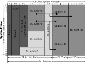
Worldwide Interoperability for Microwave Access (WiMAX) [1] is one of the state-of-the-art technologies for the last mile broadband access in Wireless Metropolitan Area Networks (WMANs). The IEEE 802.16 series [4]−[7] standardize PHY and MAC layers for WiMAX. In particular, the framework of Mobile Multi-hop Relay (MMR) operations for WiMAX is prescribed in the IEEE 802.16j-2009 standard [7], which is for extending coverage, eliminating dead angles and increasing capacity. There are two different modes for MMR operations: Transparent mode (T-Mode) and Non-Transparent mode (NT-Mode). We focus on the Path Selection Problem for IEEE 802.16j Transparent MMR (T-MMR) networks in downlink (DL) direction with at most 2-Hop operations for capacity enhancement. There exists multiple paths between an MMR-BS and an MS, each path is composed by one or two links. There are two types of links: relay links and access links. A relay link is a link between the MMR-BS and a T-RS, and an access link is a link between an MS and a super-ordinate station. An Adaptive Modulation and Coding (AMC) scheme for a link is adopted based on the link quality. The better the quality is, the higher the AMC can be, so is the spectrum efficiency. A feasible DL sub-frame for IEEE 802.16j T-MMR networks is shown in Fig. 1. For 2-Hop DL operations in IEEE 802.16j T-Mode, a DL sub-frame is divided into an Access (DA) and a Transparent (DT) zones. As shown in Fig. 1, The darkest areas are
broacasted bursts containing control messages, the brightest are bursts containing user data transmitted with direct paths, and the rest are bursts containing user data transmitted with relay paths. The relayed data in DA zone corresponds to the transmitted data in DT zone. Note that in a DA zone, resource for relaying can just be on the left-hand side of the thick line, since a T-RS can not receive data during the R-RTG time. In a DA zone, the MMR-BS can transmit data to T-RSs
FCH P re am bl e D L-M A P DL B ur st # 1 (c ar ry in g th e U L-M A P ) DL burst #3 DL burst #4 DL burst #5 DL burst #2 D L bu rs t # 6 S y s te m F ra m e S+2 S+L S+3 S+1 S S ub -c ha nn el L og ic al n um be r
OFDMA Symbol Number
k k+1 k+3 k+5 k+7 k+9 k+11 k+13 k+15 k+17
DL Access Zone DL Transparent Zone DL Sub-frame
DL burst #7
DL burst #8
DL burst #9
DL burst #10
Fig. 1: A Feasible IEEE 802.16j T-MMR DL Sub-frame. and MSs. In the mean time, T-RSs retain and MSs digest the received data, respectively. In a DT zone, the MMR-BS keeps silent in this period. In the other hand, T-RSs relay the retained data to MSs. In WiMAX systems, a user is set to subscribe for QoS connections from the operator, and each connection has minimum guaranteed bandwidth. Hence, an MS has its least bandwidth requirement, denoted as BWreq. The burst transmitted by an access link is designated to an MS. The quantum of data in the burst is the BWreq of the MS. The burst transmitted by a relay link is designated to a T-RS. The quantum of data in the burst is the summation of multiple BWreqs. Based on the standards of IEEE 802.16 series, the atomic unit for bandwidth allocation is a slot. For each link, it consumes slots to carry the data of its burst, and the adopted AMC determines how much data can be carried by a single slot, such that the required slots for each burst can be obtained. The direct access links and the relay links
consume the slots of DA zone, and the access links for the 2ndhop consume the slots of DT zone.
In this section, we outlined a feasible IEEE 802.16j T-MMR system model. The rest of this paper is organized as follows: in section II, the related work is discussed. In section III, an analytical scheme is presented to obtain the optimal zone ratio and in the other hand, to predict average spectrum efficiencies of each link type. Afterward, a novel path selection scheme is introduced to keep decent zone load-balance and spectrum efficiency. The proposed analytical and path selection schemes form a fine-grained bundle for resource allocation in IEEE 802.16j T-MMR networks. Finally, section IV reveals the simulation results and section V sums up the paper.
II. RELATEDWORK
Path Selection Problem is an essential issue for IEEE 802.16 T-MMR systems, since it directly affects the resource consumption. Any inappropriate path assignment worsens the spectrum efficiency or ruins the zone load-balance, such that the system capacity is degraded. Several literatures regarding path selection for IEEE 802.16j MMR networks have been proposed in recent years [8]−[16], they can be categorized into several approaches:
1) Number of Hops (NOH): It assigns a path with the least number of hop-counts to an MS, since a path with more hops may enforce packets experience more queuing, and more resources will be unnecessarily consumed by each link along the path. However, in 2-Hop IEEE 802.16j T-MMR networks, NOH just selects direct paths for MSs, which only consumes the resource of DA zone with low spectrum efficiency. Hence, the loadings between the DA and DT zones will be extremely unbalanced and the system will be saturated quickly.
2) Effective Spectrum Efficiency (ESE) [8]−[12]: The higher the effective spectrum efficiency is, the lower the slots are consumed. Therefore, ESE will select the path which consumes the least slots. However, without concerns for zone load-balance, the obstruction between zones will be generated soon enough to degrade the system capacity. For example, there are 9 DA and 6 DT slots available for an incomming MS. It consumes 3 DA slots if the direct path is assigned to the MS. With a relay path, 2 DA and 2 DT slots are required. ESE will select the direct path due to its less resource consumption. Afterward, it keeps comming MSs with the same situation. In the end, there are 3 MSs can be added into the system. In contrast, a better arrangement can be achieved by assigning relay paths to the 3 MSs. One DA slot can be saved by each assignment, such that the 4thMS can be added into the system with its direct path.
3) Expected Link Throughput (ELT) [13][14]: It strives for throughput as high as possible for an incomming MS such that the path which provides the highest achievable throughput for the MS will be selected. However, ELT does not consider the capacity for the whole system but only the throughput for a single user, which leads to system capacity degradation. For example, there are 8 DA and 5 DT slots available for incoming MSs. The spectrum efficiencies are 12 bytes per
slot (Bps) for the access link of a direct path, and 27 Bps and 18 Bps for the relay link and the access link of a relay path, respectively. Then, the supported bandwidths for the 1st MS are 96 and 90 bytes per frame (Bpf) by adopting the direct path and the relay path, respectively. ELT will assign the direct path to the 1st MS since higher throughput can be achieved. However, for introducing more users into the system, resources for each of them will be allocated just for meeting their minimum bandwidth requirements. Hence, assume the BWreq from the 1st MS is 54 Bpf, then 5 DA slots will be allocated for it by adopting its direct path. Let BWreqs of the 2ndand the 3rdMSs be 36 Bpf and 24 Bpf, respectively. ELT will assign relay paths to both of them due to the selection rule. Afterward, there is 1 DT slot left, which means the system is saturated since there is no DL transmission can be performed without any DA slot. In contrast, a better arrangement can be achieved by assigning relay paths to the first two MSs and a direct path to the third one, so that the 4th MS requiring for 24 Bpf can be added by adopting its direct path. This example demonstrates that ELT may lower the spectrum efficiency due to the greedness of striving throughput for a single MS, regarless of the capacity for the whole system. This situation likely happens when the available resource of DA zone is too sufficient for ELT to make good decisions.
4) Spectrum Efficiency and Load-awareness (SEL) [15][16]: It selects the path which cumulates the least con-sumption, since the higher the unbalance degree is, the sooner the saturation comes. It works properly if all paths were set to be allocated with equal number of slots. However, the resource allocation of OFDMA systems is more flexible than it thought, such that the system capacity may be degraded due to the cumulation. For example: There are 8 DA and 4 DT slots available. It exists two candidate paths for each MS: one direct path and one relay path. The former consumes 4 DA slots, the latter consumes 2 DA and 1 DT slots for its relay and access links, respectively. The 1stMS will be allocated with the relay path based on the rule. But the 2nd MS will be allocated with its direct path, since the relay path costs 4 DA slots (2 consumed by the 1st MS) and 1 DT slot, which consumes more in contrast to the direct path. The 3rdMS can be admitted just by being assigned with the relay path. In contrast, a better arrangement can be achieved by assigning relay paths to all MSs. Two DA slots can be saved such that the 4th MS can be added into the system. This example demonstrates that SEL may lower the spectrum efficiency and violate zone load-balance since it misses something important: unlike wired networks, the resources in OFDMA wireless systems can be flexibly allocated to a path according to its requirements of each link. Due to the flexibility of OFDMA, a popular path deserves more resources if it is worth being selected. As a worthy path is too popular for SEL to select, a miscalculation can be made.
The four approaches may degrade system capacity since they fail to keep decent spectrum efficiency and zone load-balance concurrently. In regard to this, we first propose an analytical scheme to obtain the optimal zone ratio and rational
average spectrum efficiencies (SEs) for each link type. We further propose a path selection scheme to keep zone load-balance to achieve high system capacity by adopting these SEs for calculations.
III. SYSTEMMODELS ANDPROPOSEDSCHEMES
The system model can be devided into two phases which are before and after the system becomes available, respectively. The analytical scheme arranges in phase I and the path selection scheme functions in phase II.
A. Phase I.
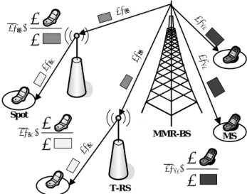
Before the system becomes available, the operator first deploys the super-ordinate stations and figures their coverages. The atomic unit in geography is called “spot”, and its size is defined by the operator. For example, it may be a 1 × 1 m2 square or a circle with 1 m diameter. With a deployment, the Candidate Paths (CPs) can be obtained according to which super-ordinate stations an MS can attach to from a given spot. The AMCs adopted to each link can be further measured or calculated. Therefore, the profiles with CP information of spots can be obtained based on a deployment. By analyzing the spot profiles, an optimal zone ratio can be obtained and the SEs for each link type can be predicted. The concept
MMR-BS T-RS SErr SErr SE da SE da SEra SEra Spot MS Frame DA DT
Fig. 2: Zone Ratio Optimization.
of zone ratio optimization is shown in Fig. 2. A path which has the least consumption is defined as the “local optimal path”. As an MS appears at a spot, it should be assigned with the local optimal path as default. For a relay path, the SErr and SEra are spectrum efficiencies of a relay and an access links respectively. The SEdais spectrum efficiency of a direct access link. Assume the MSs appear at spots in an ideally average manner, and the MS appearing at a spot requests for an average BWreq, which is denoted as BWreq. The squares
above each link represent the resources consumed by each link. Then, the ratio of resource consumptions between the
DA and DT zones can be obtained as follows:
DAalloc =X i∈N BWreq SEDAi (1) DTalloc = X i∈Nr BWreq SEDTi (2) RDA = DAalloc DAalloc+ DTalloc (3) RDT = 1 − RDA (4)
The definitions of the parameters are as follows: 1) N : The set of all spots.
2) Nr: The set of spots using relay paths as local optimal paths, Nr⊆ N .
3) i: The sequent number of spots.
4) SEDAi: The slot efficiency in DA zone for spot i with its local optimal path.
5) SEDTi: The slot efficiency in DT zone for spot i with its local optimal path.
6) DAalloc: The overall allocated slots in DA zone.
7) DTalloc: The overall allocated slots in DT zone.
8) RDA: The zone ratio for DA zone.
9) RDT: The zone ratio for DT zone.
SErr MMR-BS T-RS SErr SE da SE da SEra SEra MS Spot SEda=
SErr =
SEra =
Fig. 3: Average Spectrum Efficiency Prediction. Afterward, the SEs are predicted for three different link types: SErr, SEra and SEda. The SErr and SEra are average spectrum efficiencies of relay and access links of relay paths respectively. The SEda is the average spectrum efficiency of direct access links. The concept of SE prediction is shown in Fig. 3. An SE is calculated by dividing the transmitted data with the consumed resource. The darker MSs in Fig. 3 are assigned with direct paths and the brighter ones are assigned with relay paths as their local optimal paths. The resources consumed by different link types are differentiated with different depths of gray level.
The SEs can be more formally obtained as follows: SEda = BWreq· nd P i∈Nd BWreq SE DAi = nd P i∈Nd (SE DAi) −1 (5) SEra = BWreq· nr P i∈Nr BWreq SE DTi = nr P i∈Nr (SE DTi) −1 (6) SErr = BWreq· nr P i∈Nr BWreq SE DAi = nr P i∈Nr (SE DAi) −1 (7)
The definitions of the parameters are as follows:
1) Nd: The set of spots using direct paths as local optimal paths, Nd⊆ N .
2) nd: The number of set Nd. 3) nr: The number of set Nr.
4) n: The number of set N , n = nd+ nr.
As the analysis is completed, the system is ready to be switched from phase I to phase II.
B. Phase II.
In this phase, the introductions for incoming MSs will be performed. The system first obtains the CP information and BWreq of an MS. For each CP, the SEs obtained in phase I are adopted to rationally predict achievable capacity, which is taken as the degree of zone load-balance (ZLB). The CP which has the highest ZLB degree will be selected, so that the proposed path selection scheme is named as “ZLB”. For a
FCH P re am bl e D L-M A P DL B ur st # 1 (c ar ry in g th e U L-M A P ) Currently Allocated Required by CPk Allocated in the Future with
SErr
Allocated in the Future with SEda C ur re nt ly A llo ca te d S y s te m F ra m e S+2 S+L S+3 S+1 S S ub -c ha nn el L og ic al n um be r
OFDMA Symbol Number
k k+1 k+3 k+5 k+7 k+9 k+11 k+13 k+15 k+17
DL Access Zone DL Transparent Zone DL Sub-frame Currently Allocated Required by CPk Allocated in the Future with
SEra
Fig. 4: Virtual Allocations for System Capacity Estimation. given CP, the required slots of each zone can be obtained, and by adopting the SEs, the available slots except the required ones are used to estimate the achievable capacity in the future. Rationally, the resources for relaying should be fully utilized, since the relaying is meant to improve the spectrum efficieny and any resource for relaying not being used is taken as a wastage. Therefore, the resources which can be used for relaying should be drained out first. The resources of DA
and DT zone are virtually allocated with spectrum efficiency SErr and SEra, respectively. Afterward, the rest of available resource of DA zone shall be virtually allocated for direct access with spectrum efficiency SEda. The ZLB degree for CPk of the incoming MSj can be clarified as pseudo codes in Algorithm 1 and parameters in the algorithm are defined in Table I.
Property Parameter Description
Spectrum Efficiency
SEda Average SE of direct-access links. SEra Average SE of relay-access links. SErr Average SE of relay-relay links. SEDAk
Spectrum Efficiency of DA slots allocated for the MS assigned with CP k.
SEDTk
Spectrum Efficiency of DT slots allocated for the MS assigned with CP k.
Resource
DAavl The available DA slots in the current time.
DTavl The available DT slots in the current time.
DAreqk The DA slots requried byadopting CP k. DTreqk
The DT slots required by adopting CP k.
DAf ut k
The DA slots allocated for future usage.
DTf ut k
The DT slots allocated for future usage.
Metric
Γd k
Estimated capacity for direct access in the future. Γrk
Estimated capacity for relaying in the future.
Γk
Estimated system capacity in the future, taken as the ZLB degree of the CP k.
TABLE I: Parameters of ZLB Path Selection Scheme.
Algorithm 1 Calculate ZLB degree Γk for CPk of M Sj Require: CPk can satisfy the BWreq of M Sj
if CPk∈ CPdirectthen DAf utk ← DAavl− DAreqk DTf utk ← DTavl else DAf utk ← DAavl− DAreqk DTf utk ← DTavl− DTreqk end if Γrk← min{(SErr· DAf ut k ), (SEra· DTf ut k )} Γdk ← SEda· (DAf utk− Γrk/SErr) Γk ← Γrk+ Γdk return Γk
IV. SIMULATIONRESULTS
The decent deployments, system parameters and assump-tions will be revealed first in this section. Afterward, we evaluate system capacity for approaches mentioned in section II compared with our proposed path selection scheme. the results show that the path selection with ZLB can achieve the highest system capacity among 10,000 simulations in average. Besides, the optimal zone ratio can be indeed obtained by the proposed analytical scheme.
For the flexibility of simulations, we design a new way to construct the platform. First of all, we assume a decent number of spot types. For example, there are basically four spot types in our assumptions:
1) Spot Profile A: Spots of this profile type are more suitable for direct access. There are plenty of reasons for this condition such as: spots of this type are very close to the MMR-BS with few interferences and signal losses. The direct path is the local optimal path of this spot type since it has the least consumption.
2) Spot Profile B: Since there exists multiple paths with the least consumption as the same as the direct path, it is hard to tell whether the spots of this profile type are suitable for either direct access or with relay, after all, it could be both. Any reason for this condition could be proposed in any rational assumption, such as: a spot of this type could be either close or far to the MMR-BS and other T-RSs at the same time. The local optimal paths of this spot type are the direct path and other relay paths with the same consumption.
3) Spot Profile C: Spots of this profile type are more suitable for access with relay. There are plenty of reasons for this condition such as: spots of this type are closer to T-RSs with fewer interferences and signal losses than the MMR-BS. One or multiple relay paths with the least consumption could be the local optimal paths for this spot type.
4) Spot Profile D: Spots of this profile type can only communicate with the MMR-BS such that the direct paths are local optimal for spots of this type. This condition is usually caused by the spots of this type are out of coverage of all super-ordinate stations but the MMR-BS.
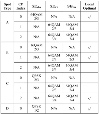
Since we only take spot profiles into consideration, there is no absolute topology in our simulation model. A given spot profile set can be represented by any rational scenario. The spot profiles are shown in Table II. We assume that the numbers of spots for each type are the same, and the probabilities for an MS appearing at each spot are equal. Infinite MSs arrive with one kind of these 4 spot profiles in equal probability. The MSs continue to join with their own BWreq, until the first blocking, the capacity accumulated by BWreq of admitted MSs is taken as the metric for examining and giving credits to a examined path selection scheme. An MS appears a given spot adopts the spot profile such as the CP list. The BWreq from an MS can vary from 384Kbps to 1.152Mbps. The PUSC permutation is adopted since it is more flexible for bandwidth allocation. In DL PUSC, two symbol time form a slot time, and one slot time by one logical
Spot Type CP Index SEda SErr SEra Local Optimal A 0 64QAM 2/3 N/A N/A √ 1 N/A 64QAM 2/3 64QAM 3/4 2 N/A 64QAM 3/4 64QAM 3/4 B 0 16QAM 2/3 N/A N/A √ 1 N/A 64QAM 2/3 64QAM 2/3 √
2 N/A 64QAM3/4 16QAM3/4
C
0 QPSK
2/3 N/A N/A
1 N/A 64QAM2/3 64QAM3/4
2 N/A 64QAM 3/4 64QAM 3/4 √ D 0 QPSK1/2 N/A N/A √
TABLE II: Four Spot Profile Types.
channel forms a logical slot, which is the atomic unit for bandwidth allocation. Since there are 46 data symbols, there are 46/2 = 23 slot time. With 30 logical channels, the number of logical slots for data transmissions is 23 × 30 = 690. The first two slot times are reserved for Message-Overhead such as: FCH, DL-MAP, UL-MAP, R-MAP and other broadcast control messages. Thus, there are 630 slots left for data transmissions. Table IV demonstrates the capacity achieved
Parameter Value
Time Domain
Useful Symbol Time (Tb=1/f) 91.4 µs Guard Time (Tg=Tb/8) 11.4 µs Symbol Duration (Ts=Tb+Tg) 102.9 µs
Frame Duration 5 ms
Number of Data Symbols 46
Frequency Domain
Operating Frequency 2.5 GHz
Channel Bandwidth 10 MHz
Sampling Frequency (Fp) 11.2 MHz
FFT Size (NFFT) 1024
Sub-carrier Frequency Spacing 10.9375 kHz
DL PUSC
Null Sub-carriers 184 Pilot Sub-carriers 120 Data Sub-carriers 720 Logical Sub-channels 30
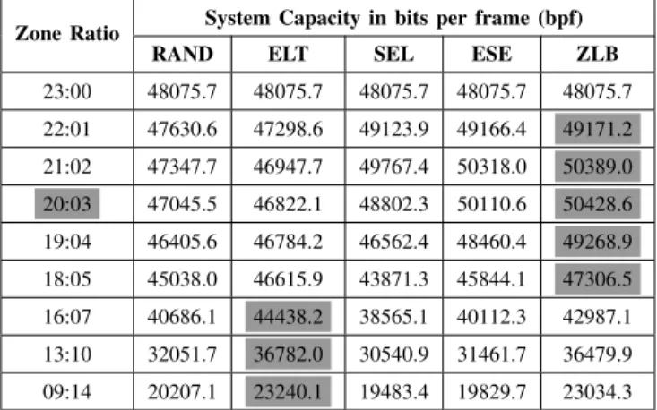
TABLE III: Parameters of the System Model. by adopting different path selection schemes. Gray fields in the table highlight the highest capacity among the schemes in a zone ratio setting. The optimal zone ratio can be obtained with 1 to 4 in advance, which is highlighted with gray field in
the zone ratio settings. The simulation results demonstrate that the proposed path selection scheme can achieve the highest capacity with the optimal zone ratio obtained by the proposed analytical scheme. Even in other zone ratio settings, ZLB still achieves magnificent system capacity.
We did not implement the NOH approach into the platform, since it always select direct path for an incoming MS. Hence, the achievable system capacity by adopting NOH will be just as the same as the IEEE 802.16e Mobile single-hop system, which has no characteristic and meaning to an IEEE 802.16j T-MMR system. Instead, we implement random (RAND) ap-proach for comparisons, since it has chance to select different paths for MSs in a random manner. ESE works well in the most but extreme cases because it takes overall spectrum efficiency without zone load-balance awareness. For SEL, due to its consumption cumulation strategy, it even worsens the system capacity in contrast to ESE. As we expected, due to the greediness of ELT, the more resource of DA zone is, the worse the miscalculation is, even RAND can beat it in high zone ratios. Although ELT can achieve the highest capacity with low zone ratios, however, these settings extremely degrade the achievable capacity already.
Zone Ratio System Capacity in bits per frame (bpf)
RAND ELT SEL ESE ZLB
23:00 48075.7 48075.7 48075.7 48075.7 48075.7 22:01 47630.6 47298.6 49123.9 49166.4 49171.2 21:02 47347.7 46947.7 49767.4 50318.0 50389.0 20:03 47045.5 46822.1 48802.3 50110.6 50428.6 19:04 46405.6 46784.2 46562.4 48460.4 49268.9 18:05 45038.0 46615.9 43871.3 45844.1 47306.5 16:07 40686.1 44438.2 38565.1 40112.3 42987.1 13:10 32051.7 36782.0 30540.9 31461.7 36479.9 09:14 20207.1 23240.1 19483.4 19829.7 23034.3
TABLE IV: System Capacity in Different Zone Ratio Settings.
V. CONCLUSIONS
This paper is proposed for path selection problem in IEEE 802.16j T-MMR networks. First of all, we outlined the sys-tem and point out the drawbacks of the four conventional approaches, which do not concurrently take care of spectrum efficiency and zone load-balance well. The spectrum efficien-cies and available resources for each zone are essential to ease and balance the load among zones. We measure the zone load-balance by calculating the ZLB degree of a given CP, which is the estimated system capacity in the future based on the virtual assignment with the CP. Since the proposed path selection scheme selects paths with zone load-balance concept, it is simply named as ZLB. For evaluating our theories, we also propose a decent system model, which is divided into two phases for clarity. Since ZLB must cooperate with a decently predicted spectrum efficiency set, we additionally propose an analytical scheme to obtain the set by constructing spot profiles
based on a given scenario. Further more, we notice that an optimal zone ratio can be obtained during the analysis. The analytical and path selection schemes are corresponding to the system model phase I and II respectively. The system capacity achieved by each scheme before system saturation is evaluated, where the saturation is defined as the first blocking event in this paper. The simulation results confirm our theories in this paper, such that the proposed analytical and path selection schemes form a fine-grained bundle of resource utility for IEEE 802.16j T-MMR systems.
REFERENCES [1] WiMAX Forum, http://www.wimaxforum.org/.
[2] IEEE 802.16 Working Group on Broadband Wireless Access Standards, http://ieee802.org/16/.
[3] IEEE 802.16’s Relay Task Group, http://ieee802.org/16/relay/. [4] “IEEE standard for Local and Metropolitan Area Networks Part 16: Air
Interface for Fixed Broadband Wireless Access Systems,” IEEE 802.16-2004, October 2004.
[5] “IEEE Standard for Local and Metropolitan Area Networks Part 16: Air Interface for Fixed and Mobile Broadband Wireless Access Systems Amendment 2:Physical and Medium Access Control Layers for Com-bined Fixed and Mobile Operation in Licensed Bands and Corrigendum 1,” IEEE 802.16e-2005, February 2006.
[6] “IEEE standard for Local and Metropolitan Area Networks Part 16: Air Interface for Broadband Wireless Access Systems,” IEEE 802.16-2009, May 2009.
[7] “IEEE Standard for Local and Metropolitan Area Networks Part 16: Air Interface for Broadband Wireless Access Systems Amendment 1: Multiple Relay Specification,” IEEE 802.16j-2009, June 2009. [8] S.S. Wang, H.C. Yin, Y.H. Tsai and S.T. Sheu, “An Effective Path
Selection Metric for IEEE 802.16-based Multi-hop Relay Networks,” 12th IEEE Symposium on Computers and Communications 2007, pp. 1051-1056, 1-4 July 2007.
[9] S.S. Wang, H.C. Yin and S.T. Sheu, “Symmetric Path Selection in IEEE 802.16 Multi-hop Relay Networks with Error Prone Links,” 4th IEEE International Conference on Circuits and Systems for Communications 2008, pp. 807-811, 26-28 May 2008.
[10] B. Wang and M. Mutka, “Path Selection for Mobile Stations in IEEE 802.16 Multihop Relay Networks,” IEEE International Symposium on World of Wireless, Mobile and Multimedia Networks 2008, pp. 1-8, 23-26 June 2008.
[11] H. Zeng and C. Zhu, “System Design and Resource Allocation in 802.16j Multi-hop Relay Systems under the User Rate Fairness Constraint,” IEEE International Conference on Communications 2009, pp. 1-8, 14-18 June 2009.
[12] W.H. Park and S. Bahka, “Resource Management Policies for Fixed Relays in Cellular Networks,” Computer Communications, vol. 32, no. 4, pp. 703-711, 4 March 2009.
[13] D.M. Shrestha, S.H. Lee, S.C. Kim and Y.B. Ko, “New Approaches for Relay Selection in IEEE 802.16 Mobile Multi-hop Relay Networks,” Lecture Notes in Computer Science, vol. 4641/2007, pp. 950-959, August 2007.
[14] S. Ann, K.G. Lee and H.S. Kim, “A Path Selection Method in IEEE 802.16j Mobile Multi-hop Relay Networks,” 2nd International Confer-ence on Sensor Technologies and Applications 2008, pp. 808-812, 25-31 August 2008.
[15] K.P. Shih, S.S. Wang and C.Y. Lien, “A High Spectral Efficiency and Load-Aware Metric for Path Selection in IEEE 802.16j Multi-hop Relay Networks,” IEEE Symposium on Computers and Communications 2009, pp. 61-66, 5-8 July 2009.
[16] Y.S. Chen, C.C. Lin and S.D. Wang, “A Traffic-Aware Routing Algo-rithm for IEEE 802.16j Multi-hop Relay Networks,” 4th International Conference on Communications and Networking in China 2009, pp. 1-10, 26-28 August 2009.