Real-time Audio Streaming Using the Adaptive Redundant Scheme over Wireless IP Networks
20
0
0
全文
(2) 1. Introduction. Although the current real-time audio streaming mechanisms are well-developed and performs well in traditional wired networks, they fail to achieve good performance in wireless/mobile networks [9, 1]. Two main issues that make wired streaming mechanisms ill-functioned in wireless networks are (1) the bandwidth of wireless networks are smaller than that of traditional wired networks and (2) the different cause of packet loss [16, 7]. In traditional wired networks, packet loss is mainly caused by network congestion. In wireless networks, the unreliable transmission media is the main cause of random packet loss [9,21,24]. The characteristic of random packet loss that exists in the wireless network environment also makes the congestion determination by loss-rate invalid. Thus, an error control mechanism that can meet wireless network’s characteristics should be adopted to form smooth presentations [14, 17, 8]. A feasible error control method is to have redundant information in a packet. Let packet i contain audio frame i. Using the redundant information method, packet i can contain some former frames i-1, i-2, etc, which normally use lower quality of codecs than that for frame i. In this way, when packet i-1 or i-2 is lost, audio frame i-1 or i-2 still can be recovered from packet i. In this paper, we propose an adaptive media dependent redundant scheme for the error control. There are two sending modes in our proposed scheme. One is called ”redundant mode” and the other one is called ”duplicated mode”. Let a packet i can contain three audio frames i, i-1, and i-2. In the redundant mode, frame i use a codec of better quality than that for frames i-1 and i-2. In the duplicated mode, frames i, i-1, and i-2 use the same codec, which has lower quality than that for frame i used in the redundant mode. The ”redundant” mode may give better quality of sound but consumes more bandwidth, while the ”duplicated” mode gives lower quality of sound but consumes less. The two modes are selected depending on the networking situation. In the wireless network environment, the bandwidth is small and each connections’s acquired bandwidth is changeable, which depends on the no. of connections originated from the corresponding base-station. To tackle this problem, we adopt a flow control scheme in our streaming mechanism. Since the random loss caused by unreliable transmission media of the wireless environment makes congestion determination by loss-rate fail, we use the round-trip time (RTT) to determine the networking situation [12]. The RTT determination of networking situation is by comparing on average RTT with the maximum RTT. Two thresholds named ”upper-ratio” and ”lower-ratio” are set. When the average RTT exceeds the upper-ratio multiplies the maximum RTT, the networking situation is set to congested. When the average RTT is under the lower-ratio multiplies the maximum RTT, the networking situation is set to unloaded. The transmission mode is switched from ”redundant” to ”duplicated” when the networking situation is determined to be congested. The transmission mode is switched from ”duplicated” to ”redundant” when the networking situation is determined to be unloaded. We call our proposed scheme that adopts the aforementioned error and flow control mechanisms ”REDUP”. A 3-tier architecture [27] is generated using REDUP. In the 3-tire architecture, an intermediate component called wireless gateway is developed. The main functions of the wireless gateway are (1) transcoding media and (2) dealing with wireless/wired streaming integration. The function of transcoding media is to transform all of the media that are 2.
(3) in wired networks into a format that can be used in wireless networks. An example is as follows. In wired networks, since the capacity of bandwidth is enough, an MP3 music stream that is 128 kbps bit-rate can be transmitted to peer clients. The MP3 music stream is too big to be transmitted in wireless networks. Thus, the wireless gateway transcodes the MP3 music stream and mixes it with the voice stream to lower down the bandwidth requirement. Since different error control and flow control methods are required in wired networks and wireless networks, the wireless gateway adopts the required mechanisms to process the streams from wired networks to wireless network and process the streams from wireless network to wired networks. The remaining part of this paper contains the detailed description of our proposed scheme. In Section 2, related works are briefly introduced. In Section 3, the 3-tire system architecture is introduced. In Section 4, a complete description of the proposed REDUP scheme is presented. In Section 5, simulation results of the proposed scheme are given. Conclusion remarks are given in section 6.. 2. Related Works. Due to the characteristics of the wireless/mobile networks, multimedia streaming over wireless/mobile networks is not trivial. In this Section, we give a brief survey of currently proposed approaches for error control and flow control for wireless/mobile networks.. 2.1. Error Control. The occurrence of packet loss is mainly due to congestion in some intermediate nodes in wired networks. On the contrary, the occurrence of packet loss is mainly due to media’s unreliability in wireless/mobile networks. Two main approaches to solve the packet loss problem in the wireless/mobile networks are (1) the retransmission approach and (2) the redundant approach. The retransmission approach is to retransmit lost packets when packet loss occurs. The redundant approach is to transmit some redundant information that is embedded with the normal packet transmission. Since we’re dealing with audio streaming that is associated with the real-time requirement, we adopt the redundant approach because the retransmission approach causes too much delay. Two categories of the redundant approach are (1) the media independent one and (2) the media dependent one. Media Independent Redundant Approach The media independent category, e.g. the Forward Error Correction(FEC) [20], uses some mathematic computation to do the error recovery. When packets are sending, some additional packets are being made and are sending. When the normal packets are lost, the additional packets can be used to do the error recovery. A typical example is the Rizzo’s algorithm [20]. The Rizzo’s algorithm uses a form of the (n, k) block erasure code, which uses linear algebra metric multiplication to count for the redundant information. The (n, k) block erasure code transmits n packets while trying to send k packets, in which n is larger than k and the n-k packets are generated by using a mathematical algorithm and are used for recovering lost packets. 3.
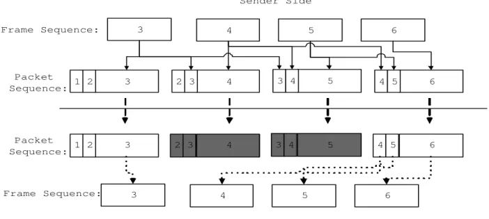
(4) Sender Side 3. Frame Sequence:. 4. 5. 6. Packet 1 2 Sequence:. 3. 2 3. 4. 3 4. 5. 4 5. 6. Packet 1 2 Sequence:. 3. 2 3. 4. 3 4. 5. 4 5. 6. Frame Sequence:. 3. 4. 5. 6. Receiver Side. Figure 1: The functional flow chart of the redundant method.. Media Dependent Redundant Approach The other redundant approach is media dependent. In the media dependent catagory, the sender encodes outgoing data using different codecs, in which different codecs use different encoding rates and give different qualities, An example is to adopt GSM and G.723 codecs, in which the GSM codec uses 13.4 kbps bit-rate while the G.723 codec uses 7.6 kbps and thus the GSM codec encodes audio data with higher quality than G.723. Figure 1 depicts the general functional flow chart of an illustrated media redundant method. In Figure 1, audio frames 3, 4, 5, and 6 are encoded by two codecs. The smaller blocks are the lower bit-rate codec’s encoded data and the larger blocks are the higher bit-rate codec’s encoded data. The smaller blocks are the redundant blocks which are used for recovering from errors. In Figure 1, gray blocks denote lost blocks, which means audio packets 4 and 5 are lost. Using the redundant approach, the lost audio frames 4 and 5 can be recovered by the redundant information contained in the following packets. Though the audio quality may be lower than that of using the lower bit-rate codec, users still can get the information that is needed. The redundant approach can be used for recovering lost packets in an environment that may lose packets occasionally, e.g. wireless/mobile networks. In order to get better recovery rate, some methods were proposed to find a better combination of codecs. Here, ”better” combination means the combination can give a higher recovery rate. Bolot proposed a way to find the ”better” combination of codecs [3]. Bolot’s algorithm calculates a ”reward” value for each combination of codecs. The ”reward” value that is calculated by using Formula (1) can reflect the recovery rate gained by the combination. The USF algorithm was proposed later to solve some problems that Bolot’s algorithm didn’t take into consideration, which are the bursty loss and the cyclical problems [14]. 4.
(5) reward =. packet loss rate after reconstruction packet loss rate before reconstruction. (1). Wireless/mobile networks usually have much smaller bandwidth than that of the wired networks. The redundant approach adds more traffic. Thus, in addition to considering the recovery rate, the bandwidth consumption rate should also be taken into consideration. The RCCS approach tries to find out a ”better” combination of codecs for the redundant mechanism by considering not only the ”reward” value but also the ”penalty” value [8]. The ”penalty” value is calculated by using Formula (2). The combination of codecs that maintains larger ”reward” and smaller ”penalty” is the better combination. penalty =. end to end delay after reconstruction end to end delay before reconstruction. (2). Unlike the media independent mechanisms, the use of media dependent redundant mechanisms has the advantage of low-latency, in which only a single-packet delay is added [15]. It makes the media dependent redundant mechanism to be suitable for interactive applications, where large end-to-end delay cannot be tolerated.. 2.2. Flow Control. The most usual way to determine whether a network is congested is by packet loss detection. It is proposed in [19] that currently existing flow control protocols for packet loss can be roughly categorized into two approaches: (1) sender-based additive increase and multiplicative decrease (AIMD) [22,5] and (2) model-based flow control [23,11]. The sender-based AIMD approach adopts the similar control scheme as that of TCP. Using the sender-based AIMD flow control approach, the receiver needs to send back ACK packets to the sender whenever packets are received. The sending rate is adjusted according to the receiving situation at the receiver side. Upon packet loss, the sender decreases its sending rate by a determined window; the sending rate slowly increases when the packet receiving situation becomes better. These kind of mechanisms are stable because of their fairness of dropping and raising sending rate. The model-based flow control (MFC) approach uses formulas that are derived by using the queuing model to calculate the current network throughput and then to determine the sending rate. Those formulas are usually made up with packet loss rate and round trip time (RTT). These mechanisms are easily to be adopted because they simply calculate throughput by a well-formed formula, but these mechanisms may be inaccurate because the determining of packet loss-rate inaccuracy and the well-formed formula may not be universally hold. Flow control mechanisms that are proposed for traditional wired networks are not suitable in the wireless environment. The main reason is that the packet loss behaviors in the wireless networks and in the traditional wired networks are very different. For the sender based AIMD, the sender drops the sending window because of losing packets of the congestion in some intermediate nodes along the path. In the wireless environment, packet loss is mainly resulted from the unreliable media. Thus, in the wireless networks, dropping sending window upon single packet loss may cause the sending rate down and 5.
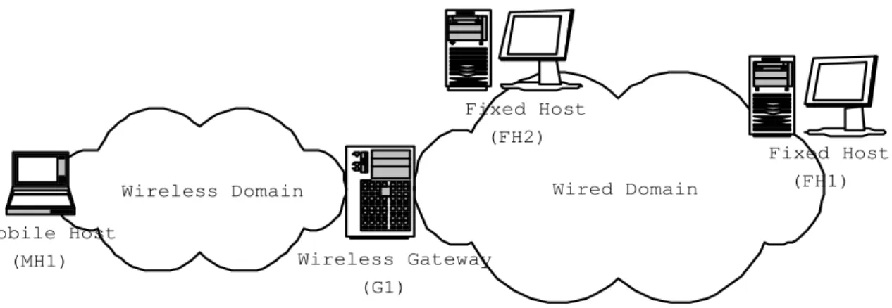
(6) Fixed Host (FH2) Wired Domain. Wireless Domain Mobile Host (MH1). Fixed Host (FH1). Wireless Gateway (G1). Figure 2: The 3-tire system architecture.. the outcome performance is not desirable. Considering of the MFC approach, the corresponding formula is composed of RTT, packet size, and lose-rate. If packet loss-rate information gathered in the wireless networks is directly being used in the formula, the resulted throughput is approximate to 0 because of the unexpected wireless losses are taken into consideration. New flow control mechanisms are proposed to dealing with the problem mentioned. The WTCP schemes [21,24] and the LDA scheme [4] were proposed to solve the problem by maintaining sending and receiving rates to determine the losses should belong to channel fading or congestion. For the MFC category, there are also new queuing models being proposed to calculate the throughput in wireless networks [10]. In addition to loss-rate, other mechanisms are also proposed to determine the network congestion in other ways. A flow control mechanism proposed by using round-trip time (RTT) to determine network status and adjusting sending rate according to the status was proposed in [12]. In the proposed approach, RTCP packets are used for calculating the round-trip time in every 5 seconds. Then, the average round-trip time is calculated and compared with the maximum round-trip time determined in the network. Congested status is determined when packet loss occurs and when the average round-trip time exceeds the upper ratio of the maximum round-trip time. Unloaded status is determined when the average round-trip time is lower than the lower-ratio of the maximum round-trip time. When the congestion status is determined after the round-trip time comparison, a TCP-like mechanism is adopted to adjust the sending rate of the sender. In [26, 25], a special value called relative one-way trip time (ROTT) is calculated for determination of the path status. A start threshold and an end threshold are formed. When ROTT exceeds the start threshold, the network status is said to enter into the congestion status. The congestion status is remaining until the ROTT is determined to be lower than the end threshold.. 3. System Architecture. Figure 2 depicts the system architecture of our 3-tire audio streaming system. Three main components of our system architecture are (1) fixed host clients, (2) mobile host. 6.
(7) clients, and (3) the wireless gateway. Two audio streams that a fixed host client can send and receive are (1) voice stream and (2) music stream. The mobile host client can only send/receive voice stream because of the bandwidth limitation in the wireless/mobile environment. In our current implementation, we adopt (1) GSM for voice and MP3 for music over wired networks, and (2) GSM for wireless networks. Thus, a wireless gateway should be allocated in the boundary of the wired networks and wireless networks in order to allow the communication between a fixed host client and a mobile host client. The main function of the wireless gateway are (1) media transcoding and (2) wired/wireless streaming integration. Transcoding A fixed host has the ability to send an MP3 music stream to the peer client that is in the wired networks. Since the wireless environment usually has smaller bandwidth than the wired environment, a mobile host in the wireless networks cannot accept the MP3 stream because of the small bandwidth of the wireless link. In order to let the mobile host clients can hear the music transmitted from fixed host clients, the wireless gateway transcodes music streams from the MP3 format to the GSM format and mix the transcoded stream with the voice stream. In this way, the bandwidth is saved from the original 141 kbps to 13 kbps, in which MP3’s bit-rate is 128kbps and GSM’s bit-rate is 13kbps. Wired/wireless streaming integration Due to the different characteristics of wired networks and wireless networks, different error control methods and mechanisms are required for dealing with the erroneous condition. The main reason for error occurrence in the wired networks is congestion and the main reason for error occurrence in the wireless networks is packet loss or packet garbling. The wireless gateway takes the role of being the streaming integration. That is, when audio packets are from wired to wireless or from wireless to wired, the wireless gateway adjusts the corresponding error control method and mechanism accordingly. The main difference between wireless audio streaming and wired audio streaming are as follows: (1) In the wired environment, packet loss is mainly resulted from congestion. Thus, it’s not reasonable to put more overhead into a congested network to gain error recovery. But it may be reasonable to put more overhead to gain recovery in wireless networks. The main reason is that the wireless environment is defaulted a lossy environment and thus packet loss does not mean the the wireless network is congested. (2) In the wired environment, the buffering mechanism is used to smooth jitters and re-ordering incoming packets. In the wireless environment, there is no network layer. Thus, no reordering is needed. But, because of the error recovery mechanism, buffering control is still needed for waiting for recovery frames.. 4. The Proposed Scheme - REDUP. In this Section, we describe our proposed scheme called REDUP, which adopts a ”redundant” mechanism and a ”duplicated” mechanism, in detail. Both ”redundant” and ”duplicated” mechanisms send the same audio packet twice or more times to make sure that the receiver side has more possibility to receive the corresponding audio packet. The main difference between the two mechanisms is that the ”redundant” mechanism uses 7.
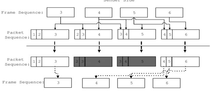
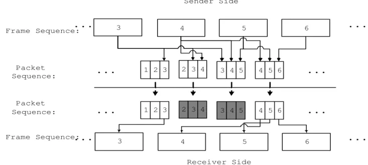
(8) Sender Side 3. Frame Sequence:. 4. 5. 6. Packet 1 2 Sequence:. 3. 2 3. 4. 3 4. 5. 4 5. 6. Packet 1 2 Sequence:. 3. 2 3. 4. 3 4. 5. 4 5. 6. Frame Sequence:. 3. 4. 5. 6. Receiver Side. Figure 3: The functional flow chart of the ”redundant” mechanism. two encoding codecs while the ”duplicated” mechanism uses only one encoding codec.. 4.1. Error Control. Two types of codecs that are defined in our scheme are master and slave. The master codec has a better quality codec and has a higher priority for playing. The slave codec has a lower quality codec and is used only when the master codec’s encoded data is lost. Two audio encoding codecs that are adopted in our scheme are GSM and G.723.1. The bit-rate of the GSM and G.723 codec are 13.4 kbps and 7 kbps respectively. In our proposed scheme, we have the GSM codec to be the master codec and the G.723 codec to be the slave codec. Figure 3 depicts the general functional flow chart of the redundant mechanism. In Figure 3, the large blocks contain the master codec’s encoded data and the smaller blocks, which are called redundant blocks, contain the slave codec’s encoded data. The number of slave blocks can be set by the application systems. The more redundant blocks are sent, (1) the more opportunities the lost data can be recovered, but on the contrary, (2) the more bandwidth is consumed and the more packet waiting time is needed to do error recovery. Thus, a compromise should be derived. In our application, the outgoing packet which contains both the master and slave encoded frames are wrapped following the standard RTP payload format defined in [17]. The ”duplicated” mechanism do error recovery in time by using additional data information. It is similar to the ”redundant” mechanism except that the ”duplicated” mechanism uses only one codec to encode audio data. That is, each frame is sent x times using a single codec. Figure 4 depicts how the ”duplicated” mechanism works, in which each frame is sent 3 times and the gray blocks denote lost packets. When some packets are lost, the receiver can recover the data as long as one packet containing the same 8.
(9) Sender Side. .... 3. Frame Sequence:. 4. 5. 6. Packet Sequence:. .... 1 2 3. 2 3 4. 3 4 5. 4 5 6. .... Packet Sequence:. .... 1 2 3. 2 3 4. 3 4 5. 4 5 6. .... Frame Sequence: .... 3. 4. 5. 6. Receiver Side. Figure 4: The functional flow chart of the ”duplicated” mechanism.. frame is received. In our proposed method, we use G.723 codec, i.e., the codec that is used as the slave codec in the ”redundant” mechanism, for the duplicate mechanism.. 4.2. Flow Control. A main feature of wireless/mobile networks is that the bandwidth of those networks are smaller than traditional wired networks. Most proposed error control mechanisms recover lost frames by sending additional information alone with the original data. Thus, these error control mechanisms put more traffic into wireless networks and make the small bandwidth wireless network have more chance to be congested. For some wireless networks, e.g., GPRS cellular network, the bandwidth of them are so small that those audio packets with original frames and error control data are sometimes too big to fit in. In this kind of small bandwidth wireless networks, we adopt a flow control mechanism to adjust our sending rate depending on network status in order to avoid the network from being congested. One way to determine whether current networks are congested or not is by the lossrate. When a base-station is congested, the incoming packets are dropped because there are not enough bandwidth for sending them. Thus, packet loss-rate can reflect to the congestion status of the base-station. This determination of base-station congestion is however not suitable for our system. This scheme fails because of the sending buffer maintained in the base-station. At the early time of congestion, since the queuing buffer is big enough to save those audio packets that exceeds the sending rate of the base-station, no packet loss can be detected. Packets are lost after a while when the sending buffer of the base-station are full - the sending rate of the base-station keeps lower than that of the sender and finally the buffer becomes full. In other words, it need some period of time to identify the congestion and the packet loss situation. 9. .... ....
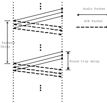
(10) .... Audio Packet. ACK Packet. .... N Packets Delay. Round trip delay. ... Figure 5: Round-trip delay calculation.. In our proposed scheme, we use round-trip delay for the determination of network congestion status. When the base-station is congested, the sending rate of the basestation drops, and the round-trip delay of each packet is therefore prolonged. Thus, prolonged round-trip delay can reflect to the network congestion status. In order to prevent frequently adjusting sending rate because of the frequent change of the status, ACK packets are only sent once in a period. In order to prevent ACK packets being lost, redundant ACK packets are also sent to ensure the sender receives at least one of them and the redundant number is set to the same number of redundant number used in the error control scheme. UDP packets are used to calculate round-trip delay because of the current TCP’s invalid performance in wireless networks. TCP cannot reflect the true round-trip time in our system because of the following reasons: (1) TCP retransmits lost packets, therefore the calculated round-trip time includes the retransmission time. (2) TCP drops the sending rate even when the rate-independent losses of packets are determined. Packet loss is rate-independent because the loss is caused by unreliable transmission media not by congestion. 3 ACK packets are sent in order to make sure that the ACK packets can be received in the sender, and only one ACK is used to calculate round-trip delay amount the 3 ACKs. Figure 5 depicts the calculation of the round-trip delay. 3 possible statuses that the networks may be in are (1) congested, (2) normal, and (3) unloaded. When current status is congested, the sending rate is dropping down to save bandwidth. No operation is taken in the normal status. The sending rate is raising when the status is unloaded. In our scheme, we adopt the network detection scheme that was proposed in [12]. The status is determined by comparing avarage round-trip time (RTT) with the maximum RTT. Two defined ratios are UpperRatio and LowerRatio. When the average RTT exceeds UpperRatio multiplies maximum RTT, the network status is set to. 10.
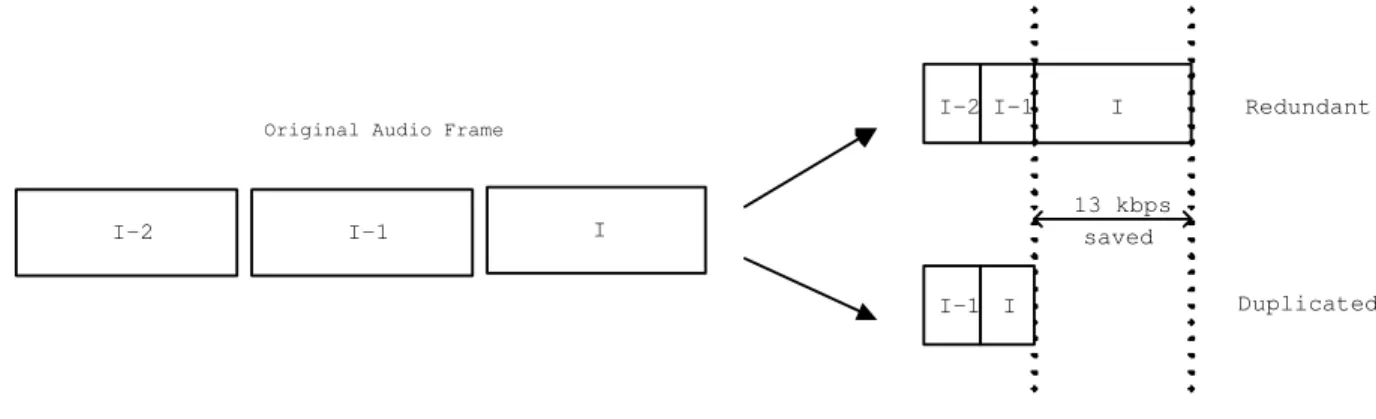
(11) AvgRTT = 0.25AvgRTT + 0.75CurRTT MaxRTT = max(CurRTT, maxRTT) CongestedBound = UpperRatio * MaxRTT UnloadedBound = LowerRatio * MaxRTT IF AvgRTT > CongestedBound THEN Network_Status = Congested ELSE IF AvgRTT < UnloadedBound THEN Network_Status = Unloaded ELSE Network_Status = Normal END IF Figure 6: Determination of current network status by RTT.. congested, and when average RTT is lower than LowerRatio multiplies maximum RTT, the network status is set to unloaded. The rests are set to normal status. Thus, larger LowerRatio is set, the more aggressively the sender tries to get back to a higher sending rate. The smaller UpperRatio is set, the more frequent the sender tries to slow down the sending rate. Figure 6 depicts the algorithm for the network determination. The average RTT is calculated by applying a smoothing factor 0.75 to the current RTT, because we want to put a heavy weight on current RTT for rapid tracing the network change with infrequent ACK feedbacks.. 4.3. The REDUP Mechanism. As that is described in the previous subsections, the ”redundant” mode has the potential to give higher quality sound and the ”duplicated” mode can consume smaller bandwidth. Thus, in the proposed REDUP scheme, the ”redundant” mechanism is used as the initial default mechanism because we want to maintain better quality while the environment can meet the need. But, when the networking situation of the wireless networks becomes worse, we can lower the bandwidth requirement by switching from ”redundant” to ”duplicated”. In the proposed scheme, when switching from ”redundant” to ”duplicate”, the master codec encoded data frames are discarded. Thus, the bandwidth saved is 13 kbps (the bit-rate of GSM codec). Figure 7 depicts the two sending modes of the system. The flow control mechanism controlls the sending rate by selecting which mode is going to be used. When RTT information tells that the current network is in the congested status and the current mode is ”redundant”, the system enters a status preparing to drop down to the ”duplicated” mode. When RTT information tells that the current network is in the unloaded status and the current mode is ”duplicated”, the system enters a status preparing to raise up to the ”redundant” mode. The reason that the system enters a preparing period but not directly switches mode is because only one RTT information may not correctly reflects a long term status. Therefore, in our proposed REDUP scheme, 11.
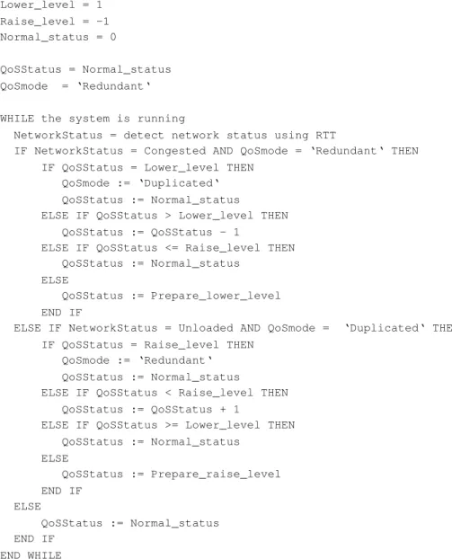
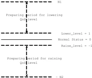
(12) I-2 I-1. I. Redundant. Original Audio Frame. I-2. I-1. 13 kbps saved. I I-1 I. Duplicated. Figure 7: The two transmission modes.. we switch modes only when the same network condition is detected by RTT information for a defined number. Figure 8 depicts the algorithm of our proposed REDUP scheme. In the proposed REDUP scheme, the value of N1 (N2) is set to the start value of the preparing period for raising (dropping) the QoS mode. Variable QoSStatus indicates the current QoS selected status. Figure 9 depicts the meaning of the QoSStatus variable in all ranges. When the value of QoSStatus is in the preparing period for dropping, the QoSStatus value is decreasing each time the congested networking status is determined. When the QoSStatus value is equal to ”Lower level”, i.e. the average RTT exceeds the upper ratio multiplies the maximum RTT for N1 continuous RTT measurements, the QoS mode switches from ”redundant” to ”duplicated”. Similarly, when the value of QoSStatus is in the preparing period for raising, the QoSStatus value is increasing each time the unloaded networking status is determined. When the QoSStatus value is equal to ”Raise level”, i.e. the average RTT is under the lower ratio multiplies the maximum RTT for N2 continuous RTT measurements, the QoS mode switches from ”duplicated” to ”redundant”. Every networking status inconsistency will interrupt current preparing period and reset the QoSStatus value to normal status. Thus, the larger the values of N1 and N2 are set, the more precise the QoS status reflects to the long term networking status, but the slower the system reacts to the congestion or unloaded network status.. 5. Performance Evaluation. We have performance analysis of the proposed REDUP scheme in a GPRS simulation environment provided by Ericsson Mobility World (EMW) in Taiwan. Figure 10 depicts the network configuration of the EMW GPRS simulation environment. The simulated cellular networks can simulate random loss caused by channel fading and background users competing in the same cell. We setup a sender-to-receiver delay of 300 ms in order to give a smooth presentation of the real-time audio streaming. Each audio frame in our system contains 60 ms of audio data. This encoding length is selected because the GSM codec needs at least 20 ms of audio data per audio frame and G.723.1 codec needs at least 30 ms of audio data per audio frame. Thus, the lowest common multiple that is 60 ms for each audio 12.
(13) Prepare_lower_level = Nl Prepare_raise_level = -N2 Lower_level = 1 Raise_level = -1 Normal_status = 0 QoSStatus = Normal_status QoSmode = ‘Redundant‘ WHILE the system is running NetworkStatus = detect network status using RTT IF NetworkStatus = Congested AND QoSmode = ‘Redundant‘ THEN IF QoSStatus = Lower_level THEN QoSmode := ‘Duplicated‘ QoSStatus := Normal_status ELSE IF QoSStatus > Lower_level THEN QoSStatus := QoSStatus - 1 ELSE IF QoSStatus <= Raise_level THEN QoSStatus := Normal_status ELSE QoSStatus := Prepare_lower_level END IF ELSE IF NetworkStatus = Unloaded AND QoSmode = ‘Duplicated‘ THEN IF QoSStatus = Raise_level THEN QoSmode := ‘Redundant‘ QoSStatus := Normal_status ELSE IF QoSStatus < Raise_level THEN QoSStatus := QoSStatus + 1 ELSE IF QoSStatus >= Lower_level THEN QoSStatus := Normal_status ELSE QoSStatus := Prepare_raise_level END IF ELSE QoSStatus := Normal_status END IF END WHILE. Figure 8: Pseudo code for the REDUP algorithm.. 13.
(14) N1. Preparing period for lowering QoS level. Lower_level = 1 Normal Status = 0 Raise_level = -1. Preparing period for raising QoS level. - N2. Figure 9: The meaning of QoSStatus variable.. The wireless gateway. Sender. Ethernet Receiver. Simulated Wireless Link. GPRS simulator. Figure 10: The network configuration of the EMW GPRS simulation environment.. 14.
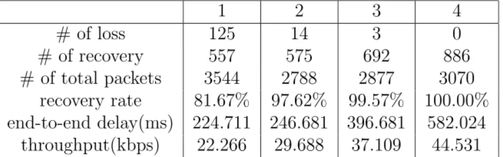
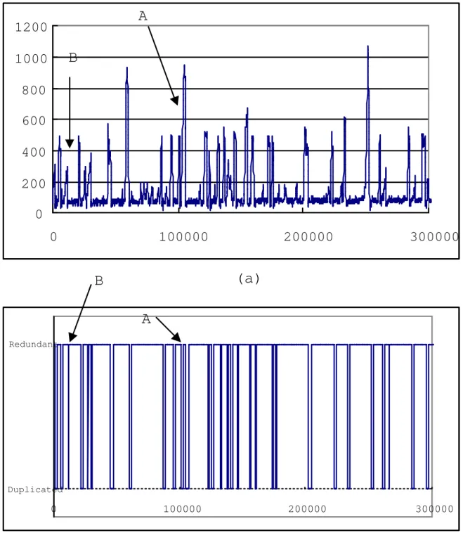
(15) 1 # of loss 125 # of recovery 557 # of total packets 3544 recovery rate 81.67% end-to-end delay(ms) 224.711 throughput(kbps) 22.266. 2 14 575 2788 97.62% 246.681 29.688. 3 3 692 2877 99.57% 396.681 37.109. 4 0 886 3070 100.00% 582.024 44.531. Table 1: The behavior of different numbers of redundant frames. frame is adopted. The number of redundant frames per packet affects the buffer length at the receiver side and this information also affects the buffering delay. The buffering length equals the number of redundant frames per packet plus one in order to wait for frame recovery at the receiver side. The limit sets for the number of redundant frame is therefore 4 because 4+1 frames with 60 ms audio data reaches the limit of our desired 300 ms delay. Table 1 lists the recovery rate and end-to-end delay for different networking configurations for selecting the good combination of codecs. Because of the bandwidth limitation in GPRS cellular network, the end-to-end delay becomes quite large when the number of redundant frames is more than 2 per packet. In the following simulations of testing REDUP parameters, the number of redundant frames per packet is therefore set to 2. Figures 11 to ?? are simulation results for different values of parameters N1 and N2 that for the oscillation control. The ACK period of these simulations is set to 300 ms, which is the buffering length, in order to have fast response to the networking situation for the real-time characteristic. Figure 11 depicts the results when N1 and N2 are both set to 1. The two parameters are set to one implies that the sending rate is adjusted every time a change of the networking situation is changed. Figure 11-(a) shows the sender to receiver delay and Figure 11-(b) shows the error control mode. The average sender to receiver delay is 148.433 ms, the maximum delay is 1071 ms, and the minimum delay is 20 ms. Since N1 and N2 are both set to 1, the mode changes very frequently, i.e., the system is very sensitive to the networking situation. For example, around the A pointed area, the mode changes to the duplicated mode and changes back to the redundant mode right away because the bandwidth has been released. But when switching back to the redundant mode, the system suddenly encounters another lack of bandwidth situation and changes back to the duplicated mode again. In the B pointed area, the system switches to the duplicated mode even though the delay just exceeds the threshold a little for a short time and switches back to the redundant mode right away. Figure 12 depicts the simulation results when N1 and N2 are both set to 3. Figure 12-(a) shows the sender to receiver delay and Figure 12-(b) shows the error control mode. The average sender to receiver delay is 244.880 ms, the maximum delay is 1402 ms and the minimum delay is 130 ms. In the E pointed area, the wide gap shows the sending mode remains in the duplicated mode for a longer time, which is caused by the larger value of N2. In the F pointed area, there are several impulse delays which exceed upperthreshold but the sending mode remains in the redundant mode, which is because of the oscillation control that ignores those single events. 15.
(16) A. 1200. B. 1000 800 600 400 200 0 0. 100000. 200000. 300000. 200000. 300000. (a). B A Redundant. Duplicated. 0. 100000. (b) Figure 11: Sender to receiver delay with N1=1 and N2=1, (a) sender to receiver delay, (b) error control mode.. 16.
(17) 1600 1400 1200. E. 1000 800. F. 600 400 200 0 0. 100000. F. 200000. (a). 300000. E. Redundant. Duplicated. 0. 100000. 200000. 300000. (b) Figure 12: Sender to receiver delay with N1=3 and N2=3, (a) sender to receiver delay, (b) error control mode.. 17.
(18) Settings N1(1)N2(1) N1(2)N2(5) N1(3)N2(3) N1(5)N2(6). Average delay 148.433 363.794 244.880 349.944. Maximum delay 1071 1191 1402 1301. Minimum delay recovery rate 20 95.23 240 97.61 130 97.29 230 93.54. Table 2: The comparison of different settings to REDUP. Table 2 shows the simulation results for different N1 and N2. From this table and Figures 11 to 12, we know that when N1 and N2 are set to 3 gives good trade-off between sender to receiver delay and mode switching. Although setting N1 and N2 to 1 gives the lowest average end-to-end delay, the frequent mode switching makes the whole system unreliable. The average end-to-end delay of setting the N1 and N2 to 3 is under the desirable limit of 300 ms, and the mode switching is not as frequent as that was in N1 and N2 setting to 1 scenario. Although the duplicated mode should give lower recovery rate because its number of redundancy frames is smaller, through the simulations we see the recovery rate is maintain in a value around the recovery rate the redundant mode should give. Thus, for the results of our scheme, we are trying to maintain the same recovery rate and to shorten the end-to-end delay that may be prolonged because of the error control.. 6. Conclusion. Two main characteristics in the wireless/mobile network environment are its (1) more unreliable transmission media and (2) lower bandwidth. In this paper, we have proposed an audio streaming scheme for dealing with the characteristics. For the more unreliable transmission media concern, packets are lost occasionally and these losses cannot be categorized to congestion. Thus, we adopt the media dependent redundant approach to recover lost frames. For the lower bandwidth concern, we adopted the approach of transcoding and mixing higher bit-rate streams, e.g., MP3 streams, with the voice stream for saving bandwidth, and then a flow control mechanism is used to adapt the sending rate to the wireless/mobile network’s situation. Round-trip time (RTT) is used for determining the current network situation. By adopting the above two methods, an adaptive redundant scheme called REDUP containing two audio sending modes, which are called ”redundant” mode and ”duplicated” mode, have been proposed in the paper. The two sending modes are formed by giving different combinations of codecs. Through the simulation results, which is executed in Ericsson EMW Taiwan, the proposed REDUP scheme can select a suitable sending mode without affecting the error recovery capability and can be adapted to the current networking situation.. References [1] M.G. Arranz, R. Aguero, L. Munoz, and P. Mahonen, ”Behavior of UDP-based Applications over IEEE 802.11 Wireless Networks”, Proceedings of 12th IEEE International Symposium on Indoor and Mobile Radio Communications, VOL.2, pp.72-77, 2001. 18.
(19) [2] S. Biaz and N. Vaidya, ”Discriminating Congestion Losses from Wireless Losses Using Inter-arrival Time at the Receiver”, Proceedings of IEEE Symposium on Application-Specific Systems and Software Engr. and Techn., pp. 10-17, 1999. [3] J. C. Bolot and A. Vega-Garcma, ”Control Mechanisms for Packet Audio in the Internet,” Proceeding of the IEEE INFOCOM, pp. 232-239, 1996. [4] S. Cen, P. C. Cosman, and G. M. Voelker ”End-to-end Differentiation of Congestion and Wireless Losses”, submitted to ACM/IEEE Trasnactions on Networking, 2002. [5] S. Cen, C. Pu, and J. Walpole, ”Flow and Congestion Control for Internet Streaming Applications”, Proceedings of Multimedia Computing and Networking, pp. 250-264, 1998. [6] S. Floyd and F. Kevin, Router Mechanisms to Support End-to-End Congestion Control, Technical Report of Network Research Group, Lawrence Berkeley National Laboratory, 1997. [7] L. Huang, S. Kumar, and C.C.J. Kuo, ”Adaptive Resource Allocation for Multimedia Services in Wireless Communication Networks”, Proceedings of International Conference on Distributed Computing Systems Workshop, pp. 307 -312, 2001. [8] M. K. Ji, S. H. Lee, T. Choi, S. H. Park, J. G. Kang, and K. D. Chung: ”Selecting an Audio Redundancy Codec Combination for Error Control in Internet Telephony.”, Proceedings of ICPADS 2001, pp. 645-652, 2001. [9] B. Leslie and M. Sandler, ”Packet Loss Resilient, Scalable Audio Compression and Streaming for IP Networks”, Proceedings of the 2nd International Conference on 3G Mobile Communication Technologies, pp. 119 -123, 2001. [10] S. Lu, T. Nandagopal, and V. Bharghavan, ”A Wireless Fair Service Algorithm for Packet Cellular Networks”, Proceedings of the 4th Annual ACM/IEEE International Conference on Mobile Computing and Networking, pp. 10-20, 1998. [11] J. Mahdavi and S. Floyd, ”TCP-Friendly Unicast Rate-Based Flow Control”, Note sent to end2end-interest mailing list, 1997. [12] S. Na and J. Ahn, ”TCP-Like Flow Control Algorithm for Real-Time Applications”, Proceedings of IEEE International Conference on Networks, pp. 99-104, 2000. [13] T. Ott, J. Kemperman, and M. Mathis, ”Window Size Behavior in TCP/IP with Constant Loss Probability”, Proceedings of the 4th IEEE Workshop on the Architecture and Implementation of High Performance Communication Systems (HPCS97), pp. 167- 182, 1997. [14] C. Padhye, K. Christensen, and W. Moreno, ”A New Adaptive FEC Loss Control Algorithm for Voice over IP Applications,” Proceedings of the 19th IEEE International Performance on Computing and Communication Conference, pp. 307-313, 2000.. 19.
(20) [15] C. Perkins, O. Hodson, and V. Hardman, ”A Survey of Packet Loss Recovery Techniques for Streaming Audio,” IEEE Network, VOL. 12, NO. 5, pp. 40-48, 1998. [16] F. Peng, S. Cheng, and J. Ma, ”An Effective Way to Improve TCP Performance in Wireless/mobile Networks”, Proceedings of EUROCOMM on Information Systems for Enhanced Public Safety and Security, pp. 250 -255, 2000. [17] C. S. Perkins, I. Kouvelas, O. Hodson, V. Hardman, M. Handley, J.-C. Bolot, A. Vega-Garcia, and S. Fosse-Parisis, ”RTP Payload for Redundant Audio Data”, IETF Audio/Video Transport Working Group, RFC2198, 1997. [18] V. Paxson, ”End-to-End Internet Packet Dynamics”, Proceedings of ACM SIGCOMM, pp. 86-92, 1997. [19] I. Rhee, V. Ozdemir, and Y. Yi. TEAR, ”TCP Emulation at Receivers-Flow Control for Multimedia Streaming”, Technical Report, Department of Computer Science, NCSU, 2000. [20] L. Rizzo, ”Effective Erasure Codes for Reliable Computer Communication Protocols”, ACM Computer Communication Review, VOL. 27, NO. 2, pp.24-36, 1997. [21] K. Ratnam and I. Matta, ”WTCP: an Efficient Mechanism for Improving TCP Performance over Wireless Links”, Proceedings of the 3rd IEEE Symposium on Computers and Communications, pp. 74-78, 1998 [22] R. Rejaie, M. Handley, and D. Estrin, ”RAP: an End-to-end Rate-based Congestion Control Mechanism for Realtime Streams in the Internet”, Proceedings of IEEE INFOCOM, pp. 1337-1345, 1999. [23] D. Sisalem and H. Schulzrinne, ”The Loss-Delay Adjusment Algorithm: a TCPfriendly Adaptation Scheme”, Proceedings of Workshop on Network and Operating System Support for Digital Audio and Video,pp. 215-226, 1998. [24] P. Sinha, N. Venkitaraman, R. Sivakumar, and V. Bharghavan, ”WTCP: a Reliable Transport Protocol for Wireless Wide-Area Networks”, TIMELY Group Research Report, 1999. [25] Y. Tobe, H. Aida, Y. Tamura, and H. Tokuda, ”Detection of Change in One-Way Delay for Analyzing the Path Status”, Proceedings of the 1st Passive and Active Measurement Workshop, pp. 61-68, 2000 [26] Y. Tobe, Y. Tamura, A. Molano, S. Ghosh, and H. Tokuda, ”Achieving Moderate Fairness for UDP Flows by Path-Status Classification”, Proceedings of the 25th Annual IEEE Conferenc on Local Computer Networks, pp. 252-261, 2000. [27] B. Yao; W.K. Fuchs, ”Proxy-based Recovery for Applications on Wireless Handheld Devices”, Proceedings of the 19th IEEE Symposium on Reliable Distributed Systems, pp. 2-10, 2000. [28] Y. Zhang, V. Paxson, and S. Shenker, ”The Stationarity of Internet Path Properties: Routing, Loss, and Throughput”, ACIRI Technical Report, 2000. 20.
(21)
數據
+7
相關文件
Is end-to-end congestion control sufficient for fair and efficient network usage. If not, what should we do
Microphone and 600 ohm line conduits shall be mechanically and electrically connected to receptacle boxes and electrically grounded to the audio system ground point.. Lines in
The main conjecture for CM elliptic curves over totally real fields. We study the cyclotomic main conjecture of Iwasawa theory for E which relates the size of Selmer groups to
Wang, Solving pseudomonotone variational inequalities and pseudocon- vex optimization problems using the projection neural network, IEEE Transactions on Neural Networks 17
Then, we tested the influence of θ for the rate of convergence of Algorithm 4.1, by using this algorithm with α = 15 and four different θ to solve a test ex- ample generated as
Define instead the imaginary.. potential, magnetic field, lattice…) Dirac-BdG Hamiltonian:. with small, and matrix
We propose a primal-dual continuation approach for the capacitated multi- facility Weber problem (CMFWP) based on its nonlinear second-order cone program (SOCP) reformulation.. The
We have also discussed the quadratic Jacobi–Davidson method combined with a nonequivalence deflation technique for slightly damped gyroscopic systems based on a computation of
