This content has been downloaded from IOPscience. Please scroll down to see the full text.
Download details:
IP Address: 140.113.38.11
This content was downloaded on 24/04/2014 at 15:08
Please note that terms and conditions apply.
Fabrication of a double-sided micro-lens array by a glass molding technique
View the table of contents for this issue, or go to the journal homepage for more 2011 J. Micromech. Microeng. 21 085020
(http://iopscience.iop.org/0960-1317/21/8/085020)
Keng-Souo Chang
, Hsiao-Yu Chou
and Chang-Pin Chou
1System Control and Integration Division, Instrument Technology Research Center,National Applied Research Laboratories, Hsinchu, Taiwan
2Department of Mechanical Engineering, National Chiao Tung University, Hsinchu, Taiwan
E-mail:msyz@itrc.narl.org.tw
Received 11 April 2011, in final form 13 June 2011 Published 12 July 2011
Online atstacks.iop.org/JMM/21/085020 Abstract
In recent years, micro-lens arrays (MLAs) have become important elements of optical systems. One function of MLAs is to create a uniform intensity of light. Compared with one-sided MLAs, the uniformity of light intensity increases with double-sided MLAs. MLAs fabricated by glass can be used in higher temperature environments or in high-energy systems. Glass-based MLAs can be fabricated by laser machining, photolithography, precision diamond grinding process and precision glass molding (PGM) technologies, but laser machining, photolithography and precision diamond grinding process technologies are not the perfect approach for mass production. Therefore, this paper proposes a method to fabricate a mold by laser micro-machining and a double-sided MLA by a PGM process. First, a micro-hole array was fabricated on the surface of a silicon carbide mold. A double-sided MLA using two molds was then formed by a PGM process. In this paper, the PGM process parameters including molding temperature and molding force are discussed. Moreover, the profile of a double-sided MLA is discussed. Finally, a double-sided MLA with a diameter of 20 mm, and lenses with a height of 52 μm, a radius of 851 μm and a pitch of 700 μm were formed on glass.
(Some figures in this article are in colour only in the electronic version)
1. Introduction
Micro-lens arrays (MLAs) are widely used in optical systems [1, 2], such as liquid crystal displays (LCDs), focal-plane elements, color filters and micro-scanners. MLAs can shape the light and create a uniform level of energy intensity. Compared with one-sided MLAs, double-sided MLAs, with a suitable optical design, increase the uniformity of the light intensity. Previous studies presented methods to fabricate MLAs: Popovic et al in 1988 and Hutley in 1990 used reflow methods [3, 4]; Lee and Han used bulk micro-machining in 2001 [5]; Cox et al used an ink-jet printing method [6]; Sizinger and Jahns used a gray scale method in 1999 [7]; Lee
et al used a LIGA technique in 2002 [8]; and Park et al used a UV light forming technique in 1999 [9]. All these methods used polymer materials.
Because high temperature phenomena are produced in high-energy systems, glass is preferred over polymer
materials. Several methods exist for fabricating a glass MLA: a precision diamond grinding process, laser machining, photolithography and a PGM technique [10,11]. Although the diamond grinding process is precise, it is not time efficient. The laser machining and photolithography technologies are not the perfect approach for mass production. The PGM technique has several advantages, such as a short cycle time, high accuracy and high profile freedom. Therefore, the PGM technique is an ideal method to quickly fabricate MLAs for mass production. The upside and underside surfaces of MLAs can be fabricated simultaneously using the PGM technique, thereby avoiding the alignment errors of double-sided MLAs. The manufacture of the mold used in the PGM process is expensive and usually requires a long processing time. Therefore, this paper presents the fabrication of a high-quality silicon carbide (SiC) mold using the laser micro-machining (LMM) process. Compared with the diamond grinding process, the LMM process is cheaper and faster. The
J. Micromech. Microeng. 21 (2011) 085020 C-Y Huang et al
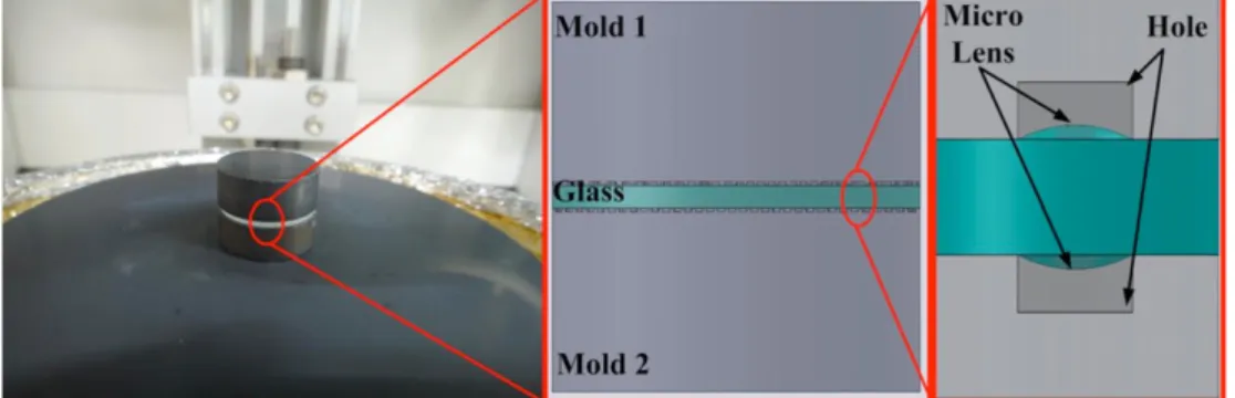
Figure 1.Diagram of glass molding.
Figure 2. Experiment flow chart.
dimensions of the micro-structure, such as the pitch, depth and shape, can all be easily adjusted in each kind of design.
2. Experiment
The micro-hole array with a diameter of 500 μm, depth of 200 μm and pitch of 700 μm on the SiC mold was made using a UV laser (AVIA 355-14, Coherent Inc.). Due to the surface tension effect, a double-sided MLA, using soda lime glass as the material, was made from two molds using the PGM system (207 HV, Toshiba). Figure 1 shows the molding diagram. The profiles of the double-sided MLA were measured using a confocal microscope (VK9700, keyence). The optical performance of the double-sided MLAs depended on the profile, for example, on the radius and height. These parameters needed to be controlled during the PGM process. Figure2shows the flow chart of the experiment.
2.1. Materials
The materials used in the PGM process require a high rigidity at high temperatures, which are usually above 600◦C. Therefore, SiC, tungsten carbide and glassy carbon have been widely used. The SiC molds with a diameter of 20 mm and thickness of 10 mm were used in this research. Soda lime glass is flat, thin and cheap, and was applied in this research to fabricate double-sided MLAs. The soda lime glass has a diameter of 20 mm and thickness of 1.2 mm.
2.2. Laser micro-machining technique
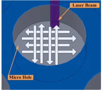
SiC, a hard, brittle and sintered material, is usually manufactured by a grinding process or diamond milling. These two processes possess processing limits that make fabricating micro-structures difficult. The spot size of lasers, such as the 30 μm UV laser, is very small and is therefore ideal for making micro-structures. The recast layer is fabricated on the metal using the laser, but is not produced with sintered materials. Therefore, a laser is an appropriate device for making a micro-hole array on the SiC mold. Figure3shows the recast layer on the metal. The laser scanning speed is an important parameter; optimal speed can obtain a high-product quality and decrease the processing time and cost. This research analyzes the profiles of micro-holes by varying laser speeds from 50 to 500 mm s−1. A UV laser with a wavelength of 355 nm and the output energy of 14.3 W was used in this experiment. The laser scanning type is bidirectional with a cross which is shown in figure4.
2.3. Precision glass molding technique
The PGM process has advantages, such as high precision, short cycle time and high profile freedom, and is widely used in high-precision mass-produced optical elements. The steps of the PGM process include heating the glass preform to the molding temperature, and then mold pressing the glass preform with a set molding force. After cooling to room temperature, the profile on the mold transforms to glass. In general, the cycle time of glass elements smaller than 20 mm in diameter only requires 18 min. In the PGM process, molding temperature and molding force are important parameters, which affect the quality of the glass. The temperature and force of the PGM process were set at 615–660 ◦C and 250–370 N in this experiment, respectively. To avoid bubbles or voids generated on the surface of double-sided MLAs, the process was performed in a vacuum.
3. Results and discussion
This paper fabricates double-sided MLAs with a micro-hole array. Therefore, the dimensions of the hole affect the profile of the lens. According to the experimental results, the lens radius increases with the diameter of the hole. A very large hole diameter causes the upper surface of the lens to be flat, not
Figure 3.After the laser process (a) with a recast layer on the metal and (b) without a recast layer on SiC.
Figure 4. Schematic diagram of the laser processing path type.
curved. But a very small hole diameter leads to the splitting of the glass structure and the clogging of holes during the PGM process. Therefore, a hole diameter of 500 μm was used in this research. The following sections discuss the effects of laser scanning speed, molding temperature and molding force on the double-sided MLA profile.
3.1. Effect of laser scanning speed
An increased laser scanning speed leads to a decrease in processing time and cost. A high speed causes a decrease in laser energy per unit area and, therefore, a decrease in hole depth. Exceeding the speed determined by the limit of the scanning mirror leads to an insufficient overlap area, and hence, the holes on the SiC mold are unacceptable for the discontinuous profile. If the speed is too slow, the laser energy per unit area increases and leads to an increase in roughness on the SiC surface.
The relationship between the laser scanning speed and the depth of the hole is shown in figure5. The hole depths were measured using a precision confocal microscope. After evaluating the processing time and quality of holes, a laser
Figure 5. Relationship between the laser scanning speed and depth of hole.
scanning speed of 400 mm s−1was selected at an output energy of 14.3 W. A photograph of the mold is shown in figure6. The diameter is 20 mm for the SiC mold and 500 μm for each hole.
The different micro-hole array on the SiC mold can be obtained by the simple adjustment of laser parameters. Figure7shows the different diameters and pitches of micro-hole arrays on the SiC mold. Moreover, the alignment position of the upside and underside lens can be adjusted by alignment fixture that can be designed on the molds.
3.2. Effect of molding temperature and molding force
When the molding temperature range was controlled between 615 and 660◦C, the adhesion of the glass material decreased with increased temperature. Therefore, the glass material was easily deformed at higher temperatures. A higher molding temperature led to a longer cooling time and higher consumption of energy. A very low temperature led to poorly formed or broken glass. Therefore, the optimal molding temperature is important in the PGM process. Figure 8
J. Micromech. Microeng. 21 (2011) 085020 C-Y Huang et al
Figure 6.Micro-hole measured by precision confocal microscope.
(a) (b)
Figure 7.Micro-holes on SiC mold with (a) 500 μm in diameter and 700 μm in pitch, (b) 400 μm in diameter and 600 μm in pitch.
Figure 8. Relationship between the molding temperature and radius/height of the double-sided MLA.
shows the relationship between the molding temperature and the radius/height of the double-sided MLA. The height of the double-sided MLA, including both the upside and underside lens, increased as the molding temperature increased from 615 to 660 ◦C. The underside lens is higher than the upside lens. Because the mold is placed directly on the molding machine, as shown in figure 1, the heating method of the underside mold is not only radiation but also
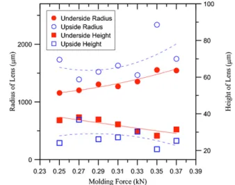
Figure 9. Relationship between the molding force and radius/height of double-sided MLAs.
conduction. This phenomenon causes the temperature of the glass underside to be higher than the upside. The temperature difference leads to the underside lens being higher than the upside lens. Because the diameter of the hole is fixed at 500 μm, an increase in the lens height creates a decrease in the lens radius.
Figure 9 shows the relationship between the molding force and the radius/height of the double-sided MLA. A
(a) (b)
(c) (d)
(e)
Figure 11.(a) Photograph of the double-sided MLA, (b) 200×, (c) 400× and (d) 1000×.
molding force between 0.25 and 0.37 kN was selected in this research at a molding temperature of 630◦C. Compared to the molding temperature, the effect of molding force on the lens height is unclear. The difference in the lens height is only 16 μm between the maximum and minimum. An increase in the lens height also leads to a decrease in the lens radius.
The cross-sectional photograph of the double-sided MLA is shown in figure10. After the PGM process, the double-sided MLA was fabricated on soda lime glass. Figures10(a) and (c) are 400× photographs and figure10(b) is 200× using
a confocal microscope. Figure11(a) shows a photograph of the double-sided MLA; figures11(b)–(d) are for 200×, 400×
J. Micromech. Microeng. 21 (2011) 085020 C-Y Huang et al
The lens dimensions are 851 μm in radius, 460 μm in width, 52 μm in height and 700 μm in pitch.
4. Conclusions
This paper has presented the fabrication of a double-sided MLA on soda lime glass using a laser and a PGM process. Compared with the grinding process, the PGM process with a cycle time of 18 min was more time-efficient. By analyzing the experimental results, profile charts of the lens with respect to laser scanning speed, molding temperature and molding force were obtained. The experiment showed that the double-sided MLA had dimensions of 851 μm in radius, 460 μm in width, 52 μm in height and 700 μm in pitch.
References
[1] Peter Y A, Herzig H P and Dandliker R 2002 Micro-optical fiber switch for a large number of interconnects: optical design considerations and experimental realizations using microlens arrays IEEE J. Sel. Top. Quantum Electron.
846–57
[2] Borrelli N F, Morse D L, Bellman R H and Morgon W L 1985 Photolytic technique for producing microlenses in
photosensitive glass Appl. Opt.242520–5
[3] Popovic Z D, Sprague R A and Connell G A N 1988 Technique for the monolithic fabrication of microlens arrays Appl. Opt.271281–4
[4] Hutley M C 1990 Optical techniques for the generation of microlens arrays J. Mod. Opt.37253–65
[5] Lee C S and Han C H 2001 A novel refractive silicon microlens array using bulk micromachining technology
Sensors Actuators A8887–90
[6] Cox W R, Chen T, Hayes D J W, Royall C, Ting C and Donald J H 2001 Micro-optics fabrication by ink-jet printing Opt. Photonics News1232–5
[7] Sizinger S and Jahns J 1999 Microoptics (Germany: Wiley-VCH)
[8] Lee S K, Lee K C and Lee S S 2002 A simple method for microlens fabrication by the modified LIGA process J. Micromech. Microeng.
12334–40
[9] Park E H, Kim M J and Kwon Y S 1999 Microlens for efficient coupling between LED and optical fiber IEEE
Photonics Technol. Lett.11439–41
[10] Chen Y, Yi A Y, Yao D, Klocke F and Pongs G 2008 A reflow process for glass microlens array fabrication by use of precision compression molding J. Micromech. Microeng.
18055022
[11] Firestone G C, Jain A and Yi A Y 2005 Precision laboratory apparatus for high temperature compression molding of glass lenses Am. Inst. Phys.
76063101