A Retargetable Code Generation Methodology for Embedded Systems
6
0
0
全文
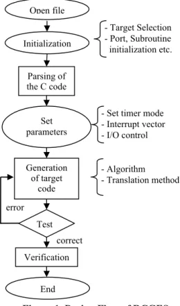
(2) Int. Computer Symposium, Dec. 15-17, 2004, Taipei, Taiwan.. Regarding synthesis tools for HSC (HardwareSoftware Codesign), Parkinson et al [2] developed a tool to translate sections of C code into behavioral VHDL. Similarly, Rettberg [3] proposed a useful flowchart based on the state flow models with multiple input and a single output for code generation. In 2002, Chung et al [4] not only created a framework for the optimization of embedded software but also presented algorithms and a tool flow to reduce the computational effort of programs. By using a simple tree pattern matching algorithm for code generator, Chen [5] used a simple tree pattern matching algorithm in the code generator to reduce the matching time by 69% effectively. Leupers [6] provided a survey of methods and techniques dedicated to efficient code generation for embedded processors. Lee [7] had introduced the Interrupt Time Petri Nets (ITPN) model and the Interrupt-Based Quasi-Dynamic Scheduling (IQDS) algorithm to model embedded systems with interrupt property and find task schedules with time constraints. However, this work lacks flexibility and productivity, i.e. except for 8051 micro-controller code generation for others embedded systems may fail. Hsiung [8] proposed a Time-Extended QuasiStatic Scheduling algorithm (TEQSS) to synthesize real-time embedded software code through a set of Time Complex-Choice Petri Nets. TEQSS mainly focused to meet memory and time constraints but did not address retargetable code generation for embedded systems. In 2004, Lee and Hsiung [9] proposed an Embedded Software Synthesis and Prototyping (ESSP) methodology to solve the software synthesis, software verification, code generation, and system emulation. Manohar and Bhatia [10] proposed a tool for automated code generation in designing user interfaces on character terminals and designed a user interface tool for designer to solve problems on complex library call. This tool lacks of facilitation because it did not support mouse events. Charot and Messe [11] proposed a flexible code generation framework for the design of application specific programmable processors and used library modules to achieve flexible compilation passes such as code generation and scheduling. The framework consists of two levels, one was retargeting modules that defined compilation flow, and the other allowed user to select and link modules from the library for building a compiler. Unfortunately, the library was incomplete when the paper was published.. 3.. Retargetable Methodology. Code. applications, retargetable code generation for embedded systems is seen as the most significant issue that most researchers are eager to solve. However, many programs are still written in assembly code to meet constraints such as execution time, code size, and power consumption. But there is no doubt that assembly code lacks flexibility, efficiency, and productivity. As solution, we proposed a translation methodology that combined XML (eXtensible Markup Language) tree and Binary tree to develop retargetable embedded software. The proposed methodology was successfully applied to 8051-based and PIC-based embedded processors as described the following sections.. 3.1. Design Flow of Retargetable Code Generation for Embedded System The RCGES design flow is shown in Fig. 1. There are six design steps in RCGES which are listed as following: Step (1), Initialization: choosing the type of processor in target embedded system, initialization and setup input/output ports for embedded processor. Step (2), Parsing: parsing syntax, variables, keywords, operator and operand. Step.(3),\Set Parameters: design a user friendly interface for setting interrupt vector, timer and I/O interface in retargetable embedded processors. Step.(4),.Translate the source C code into the embedded C code by RCGES algorithm for target Open file Initialization. - Target Selection - Port, Subroutine initialization etc.. Parsing of the C code. Set parameters. - Set timer mode - Interrupt vector - I/O control. Generation of target code. - Algorithm - Translation method. error Test correct. Generation. Verification. The increased applications of embedded systems have resulted in code generation becoming more and more important. In order to cope with the variety of. End. Figure 1. Design Flow of RCGES. 766.
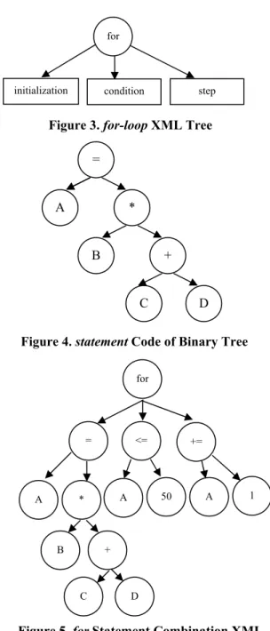
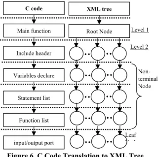
(3) Int. Computer Symposium, Dec. 15-17, 2004, Taipei, Taiwan.. processor in embedded system. Step.(5), Test: the output code from code generation algorithm of RCGES be tested by Keil C Compiler [12] and HI-Tech compiler [13] depending on 8051-based and PIC-based embedded systems, respectively. Step (6) Verification: we use two kinds of emulation platform, 8051 and PIC16F of WINICE [14] series, to verify the two generation codes, respectively.. which includes three parameters: initialization, condition, and step statement. The for-loop code will be translated into XML tree which is shown in Figure 3. Regarding to the operation statement, it will be translated into Binary Tree. For example, a statement A=B*(C+D) be represented by a Binary tree which is shown in Figure 4. Figure 5 shows the combination of XML and Binary Tree. Then, front, main program and subroutine are essential to be translated into trees. A GUI will be used to set the input/output port parameters depending on target embedded systems. Finally, an XML tree will be constructed automatically as shown in Figure 6.. 3.2. Translation Method We propose a translation method to transform a source C code into a embedded C code. The proposed translation method combines XML tree and Binary tree. The main reason of choosing XML tree for translation method in this work is that XML is a language for describing others language. Therefore, an ANSI C code can be translated into a XML tree. XML is an eXtensible Markup Language that designed to improve the functionality of the Web by providing more flexible and adaptable information identification. In other words, XML is a kind of markup language to help different types of document to describe its data structure and facilitates data exchange among variety of systems. A specific definition of XML tree is shown as below and an example of XML tree is provided in Figure. 2. z Root Node: a node without any parent nodes in a tree map, such as node A. z Leaf Node: a node without any child nodes, such as nodes D, E, F, G, H, I, J, and K. z Non-terminal Node: meaning non-leaf Node, such as node B and C. z Degree: the number of child node in a node. For example, the degree of B Node is 2. z Level: the total of levels from Root Node level to Leaf Node level. For example, A Node is in level 1, B to G Node are in level 2, and H to K are in level 3. z Height (Depth): the maximum level number of a tree. For example, the height in Fig. 2 is 3. For example, there is a for-loop in ANSI C code. Level 1. A. 3.3. Code Generation Algorithm In the process of developing the software, the. for. initialization. step. condition. Figure 3. for-loop XML Tree = A. * B. + C. D. Figure 4. statement Code of Binary Tree for. =. A. <=. 50. A. *. +=. A. 1. Level 2. B. C. D. I. J. E. F. B. G. Level 3. H. +. C. K. D. Figure 5. for Statement Combination XML Tree and Binary Tree. Figure 2. A Simple XML Tree. 767.
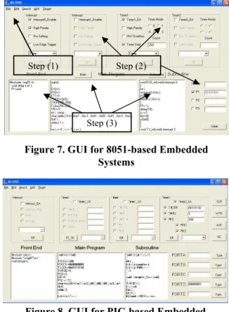
(4) Int. Computer Symposium, Dec. 15-17, 2004, Taipei, Taiwan.. C code. XML tree. Main function. Root Node. system such as input/output initial value, interrupt and timer enable/disable, etc. Step (3) is the parameter setting of interrupt, time, and input/output depending design requirement. The core of parsing program is performed in step (4) to step (6). The algorithm has to check what kind of the token such as keyword, comment, head file of the C code, etc., or a variable. In step (7), we transfer token into equation or flow control equation. For example a = b + c, where a, b, c, =, and + are also a token. Step (8) is mapping parameters, such as interrupt, timer, variable type, input/output and subroutine of interrupt or timer, into a program code. Step (9) is a function of translation. During the period of translation of ANSI C code into embedded C code, both XML tree and Binary tree is used to build for RCGES which handles some statements between variables of ANSI C code and input/output port of embedded C code, such as variables mapping, selection, and loop functions.. Level 1 Level 2. Include header Nonterminal Node. Variables declare. Statement list. Function list. input/output port. Leaf N d. Figure 6. C Code Translation to XML Tree program code is automatically generated based on the different target embedded systems. Therefore, the system designers will only be required to import an ANSI C code and the retarget embedded C code will be generated by our proposed code generation algorithm. The difference of ANSI C code and embedded C code is that the former needs to add some parameter setting such as input/output port, timer, interrupt. The code generation algorithm of RCGES is shown in Table 1. The purpose of code generation algorithm is automatically generation embedded C code from ANSI C code. In Table 1, step (1) opens the source file and assigns a name for output file. Step (2) is to set the initial condition of embedded. 3.4. Graphical User Interface of RCGES In our RCGES methodology, a graphical user interface (GUI) is supported for the selection of an embedded processor and the setting of parameters. The GUI of 8051-based and PIC-based embedded systems is shown on Figure 7 and Figure 8, respectively. The main operation has three steps which are described as follows: Step.(1) is to open a file and select the target processor: designers should open a source code from the menu ‘File’ and select target processor. Step.(2) is to set the initial condition of embedded processor including the parameter of interrupt, timer, input/output port. Interrupt mode includes int0, int1 and trigger by low-level or negativeedge. In timer0 and timer1, designers can also set timer priority and the amount of counter. Step.(3) is to generate and display retargetable embedded software.. Table 1. Code Generation Algorithm Procedure Code_Generation Begin Open_file( ); (1) Initialization(); (2) Parameter_Setting( );//Set the interrupt, vector, timer, I/O port type, etc. (3) While( file is not ending) (4) GetToken(); //get the variable from the file (5) if(token = = keyword)//include, int, char, while for (6) {if(Token= = Selection) //if, case, else…etc. Selection ( ); //parsing if, else, and get the condition else if(Token= = Loop) //while, for … Loop (); //get the loop times, and ending condition else if ( Token= = HeadFille) //include Headfile( ); //get the head file else if (Token = = Declare) Declare ( ); //store the variable, array, and subroutine, else Comment ( ); }// end of if else Variable ( ); End;//end of While (7) Statement ( ); (8) Translation ( ); (9) End;//end of Begin End;//end of Procedure. 4. Embedded System Examples In this section, we use two embedded system examples to illustrate our translating methodology: LED display control of advertisement (LDCA) and four phases stepping motor control (FPSMC). The experiment environment of embedded system include three parts which are GUI on Figure 7 and Figure 8 for parameter setting of embedded systems, two compiler namely Keil C compiler and PIC C compiler for producing executable specification code and WINICE emulation board with 8051 and PIC for testing embedded software functionality. The WINICE emulation board specification includes a 80(C)51/52 CPU (Central Processing Unit), 16MHz working frequency, 64 K-byte program memory, 64 K-byte data memory and parallel transmission port. 768.
(5) Int. Computer Symposium, Dec. 15-17, 2004, Taipei, Taiwan.. interface. The specification of PIC emulation board is 16F877 CPU, 20MHz working frequency and 8 kword memory. In this experiment, timer, interrupt and input/output port functionality is tested when system is in initialization state. When all of functionality is work correctly, two embedded system examples are illustrated by RCGES. The first example is a LED display control of advertisement that system function is 8 LED turning on sequentially from left to right or from right to left controlled by interrupt or timer in embedded system. Therefore, system designer firstly edit an ANSI C code as main program which is shown in Table 2. Then designer use our proposed graphical user interface to set parameter such as initialization, interrupt, timer mode or input/output value for system constraints. Applying the RCGES to generate code for 8051-based embedded system is shown on Figure 7. The same method is applied to PIC-based embedded system then the generation code is shown on Figure 8. Main program define a set of table for either P1 base on 8051 or PROTD base on PIC output which waiting for interrupt or timer mode. If interrupt is ‘0’, then LED will turn on from left to right sequentially. In contrast, if Timer mode set to ‘0’, LED will turn on from right to left. The partial embedded C code of the first example for 8051based and PIC-based system is shown in Table 3 and Table 4, respectively. Furthermore, initial values, interrupts and timer mode are also generated by RCGES. Another example is a four phase stepping motor control (FPSMC). The function of FPSMC is using interrupt and Timer to control the direction of motor. If Timer mode set to ‘0’, the motor turns clockwise. If interrupt is ‘0’, the motor turns counterclockwise. Because the page limited, we show the partial generation code in Table 5 and Table 6 for 8051based and PIC-based embedded system, respectively. The output embedded C code from RCGES is compiled using Keil C and Hi-Tech C to generate execution code for 8051-based processors and PICbased processors, respectively. WINICE emulation board of 8051 and PIC-16/17 are used to verify. Step (1). Step (2). Step (3). Figure 7. GUI for 8051-based Embedded Systems. Figure 8. GUI for PIC-based Embedded Systems Table 3. Partial Embedded C Code of LDCA for 8051-based Embedded Systems #include <reg51.h> void delay ( int ) ; int k=2000; char OUT=0x80; P1=11111111; main() {ET1=1;PT1=1;TMOD=0x02;TH0=(256-250); TL0=(256-250); TR1=1;EX0=1;PX0=1;IE0=1;int i , temp ; char table [ 8 ]={ 0xe7 , 0xc3 , 0x81 , 0x00 , 0x81 , 0xc3 , 0xe7 , 0xff } ; while ( 1 ) {for ( i = 0 ; i <= 7 ; i ++ ) {P1 = table [ i ] ;delay ( 10000 ) ;}}}. Table 4. Partial Embedded C Code of LDCA for PIC-based Embedded Systems. Table 2. ANSI C code for LED Display Control of Advertisement. #include <pic.h> #include "cnfig877a.h" void delay(int) ; void main(void) {TRISD=0x00; PORTD=0b00000001; T2CON=0b01111110; TMR2IE=1; PEIE=1; GIE=1; PR2 = 155; char table[8]={0xe7,0xc3,0x81,0x00,0x81,0xc3,0xe7, 0xff} ; while (1){for(i=0;i<=7;i++ ) {PORTD=table[i] ;delay (10000) ;}}}. # include < stdio.h > # include < stdlib.h > void delay(int) ; main() {int i,temp; char table[8]={0xe7,0xc3,0x81,0x00,0x81,0xc3,0xe7, 0xff} ; while (1) { for(i=0;i<=7;i++ ) {temp=table[i] ; delay (10000) ;}}} void delay(int count) {int i,j; for(i=0;i<count;i++ ) for(j=0;j<1500;j++ ) ; …}. 769.
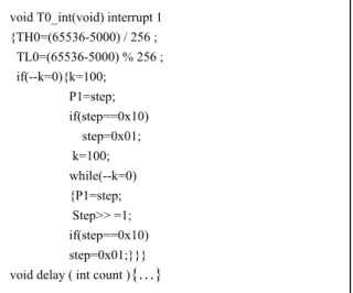
(6) Int. Computer Symposium, Dec. 15-17, 2004, Taipei, Taiwan.. Table 5. Partial Embedded C Code of FPSMC for 8051-based Embedded Systems. advertisement (LDCA) and four phases stepping motor control (FPSMC), on WINICE emulation board. In the future, we will focus on the automatic code generation of ARM-based and DSP embedded systems.. void T0_int(void) interrupt 1 {TH0=(65536-5000) / 256 ; TL0=(65536-5000) % 256 ; if(--k=0){k=100;. References. P1=step; if(step==0x10). [1]. step=0x01; k=100; while(--k=0). [2]. {P1=step; Step>> =1; if(step==0x10) step=0x01;}}}. [3]. void delay ( int count ){…}. Table 6. Partial Embedded C Code of FPSMC for PIC-based Embedded Systems [4]. void delay(int count){ int i,j; for(i=0;i<count;i++ ) for(j=0;j<1500;j++ ){ ; }}. [5]. void interrupt isr_Sevr (void){ TMR2IF=0; if (--k=0) {k=100; PORTD=step; if (step==0x10). [6]. {step=0x01; k=100; while(--k=0). [7]. {PORTD=step; step>>=1; if (step==0x10) {step=0x01; }}}}}. RCGES feasibility. The experiment result has shown that the generation embedded C codes by RCGES can be checked the correction through SW compiler verification or emulation board such as 8051 and PIC of WINICE. In case of external circuit examples, we not only download the generation code of RCGES into retargetable embedded systems, but also verify circuit functionality.. [8]. 5. Conclusion and Future Work. [10]. [9]. A retargetable code generation methodology, namely RCGES, was proposed to solve automatically generation embedded C code and provide a GUI for the parameter setting of embedded processors. The XML tree and Binary tree were successfully used as an interface for translating C programs for appropriate embedded processors in RCGES. We have shown the feasibility through two embedded system examples, LED display control of. [11]. [12] [13] [14]. 770. R. Leupers, “Code Generation for Embedded Processors,” In Proceedings of the 13th International Symposium on System Synthesis, pp. 173-178, Sep. 2000. M. F. Parkinson, P. M. Taylor and S. Parameswaran, “C to VHDL Converter in a Codesign Environment,” Spring Conference on VHDL International Users Forum, pp. 100-109, 1994. A. Rettberg, E. Erpenbach, J. Tacken, C. Rust and B. Kleinjohann, “Compilation of Flow Diagrams into Target Code for Embedded Systems,” In Proceedings of the Second International Workshop on Compiler and Architecture Support for Embedded Systems (CASES'99), Washington, D.C. USA, 1999. E.Y. Chung, L. Benini, G. DeMicheli, G. Luculli and M. Carilli, “Value-Sensitive Automatic Code Specialization for Embedded Software,” IEEE Transactions on Computer-Aided Design of Integrated Circuits and Systems, pp.1051-1067, 2002. T.S. Chen, F. Lai and R. J. Shang, “A Simple Tree Pattern Matching Algorithm for Code Generator,” In Proceedings of the 9th Annual International Computer Software and Applications Conference, COMPSAC, pp. 162-167, Aug. 1995. R. Leupers, “Compiler design issues for embedded processors,” Journal of Design & Test of Computers, IEEE, vol. 19, no 4, pp. 51-58, 2002. T.-Y. Lee, P.-A. Hsiung, I-M. Wu, C.-C. Tsai, and W.-T. Lee, “The Design of a Synthesis Tool for Interrupt-based Real Time Embedded Software,” In Proceeding of the International Conference on Informatics Cybernetics and Systems (ICICS’2003, Kaohsiung, Taiwan), pp. 1284-1289, Dec. 2003. P.-A. Hsiung, T.-Y. Lee, and F.-S. Su, “Formal Synthesis and Code Generation of Real-Time Embedded Software Using Time-Extended QuasiStatic Scheduling,” In Proceedings of the 9th AsiaPacific Software Engineering Conference (APSE’02), IEEE Computer Society Press, pp. 395-404, Dec. 2002. T.-Y. Lee and P.-A. Hsiung, “Embedded Software Synthesis and Prototyping,” IEEE Transactions on Consumer Electronics, vol. 50, no. 1, pp. 386-392, Feb. 2004. N. Manohar, M. P. S. Bhatia, “A tool for automated code generation for designing user interfaces on character terminals,” In IEEE Proceedings SoutheastCon 2001, pp. 155-159, Mar.-Apr. 2001. F. Charot and V. Messé, “A flexible code generation framework for the design of application specific programmable processors,” In Proceedings of the Seventh International Workshop on Hardware/Software Codesign, pp. 27-31, Mar. 1999. http://www.keil.com/c51/. http: //www.htsoft.com. http://www.microtime.com.tw/product/product.htm..
(7)
數據
+2
相關文件
introduces a methodology for extending regular classification algorithms to cost-sensitive ones with any cost. provides strong theoretical support for
Hence, code for each non zero AC coefficient is composed of a basecode (corresponding to runlength/category) and a code corresponding to offset in.. Standard tables vs
In this paper, we provide new decidability and undecidability results for classes of linear hybrid systems, and we show that some algorithms for the analysis of timed automata can
Elements of Computing Systems, Nisan & Schocken, MIT Press, www.nand2tetris.org , Chapter 1: Compiler II: Code Generation slide
Extend the syntax analyzer into a full-blown compiler that, instead of passive XML code, generates executable VM code. Two challenges: (a) handling data, and (b)
Experiment code often includes messy scripts for various settings in the paper – useful for reviewers Software: for general users. One or a few reasonable settings with a
• tiny (a single segment, used by .com programs), small (one code segment and one data segment), medium (multiple code segments and a single data segment), compact (one code
Second, the 80186 object code (Real Mode, Large Model) generated using the Borland C/C++ compiler is compatible with all 80x86 derivative processors from Intel, AMD or Cyrix..
