IEEETRANSACTIONSON INDUSTRIALELECTRONICS,VOL.IE-29, NO. 4, NOVEMBER 1982
Design
and
Implementation
of
a
Fully Digital
DC
Servo
System Based
on a
Single-Chip
Microcomputer
PEI-CHONG TANG, SHUI-SHONG LU, AND YUNG-CHUN WU
Abstract-A single-chip microcomputer is used to design a fully
digital dc servo system to replace the conventional analog circuits.
Thismicrocomputer performsthreemain tasks: thefiringcontrol ofa
three-phase full-wavethyristordual converter; thecompensationfor thenonlinearandloading effectin theconverter; andcompensations ofposition loop and rate loop. With nocurrentfeedback and min-imum components, this dc servo system provides fast transient re-sponseandhigh reliability.
I.INTRODUCTION
M ICROPROCESSOR applications in the industrial control are increasing rapidly in recentyears. For the
thyristor-driven dc servo systems, several
microprocessor-based
designs have beenimplementedtoreplace
the conventionalanalog
anddiscrete digital circuits
[1
]-[3]
. Ohmae eta!.[1
] used abit-slice microprocessor system to
design
aspeed
regulation
sys-tem by adual-mode currentloop-control
method. Chan etal.[2]
-[3] used an 8-bit microprocessor system to control thespeed and position of a dc motor
by
a different currentloop-controlled method. In the case of
thyristor-driven
dc servo systems, the criticalproblem
is to find an easy way to compensate the nonlinear andloading
effect ofthyristor
con-verter. From this point of view, the methodsproposed
by OhmaeandChanetal. areunsatisfactory.
Recently, Tang, Lu, and Wu
[4]
proposed a cascadenon-linear compensation scheme to compensate the nonlinear and
loading
effect of thyristor converter. In this scheme, no currentloops wererequired and simple computing algorithmswere used. Thus, the microprocessor-based controller design
was simplified in both hardware and software. In
addition,
it was shown that this compensated thyristor-driven dc servo system could be regarded as a quasi-linear system. Thus, the
control-loop design was simplified. In another paper,
Tang,
Lu, and Wu[5]
introduced a microprocessor-based firing scheme to provide maximumfiring
range with minimumfiring delay. This scheme used minimum components and no ad-justment was required. In this paper, asingle-chip microcom-puter isused toimplement a fast-response thyristor-driven dc servo system based on these two schemes. This circuit usesfullydigital components with minimum hardware.
II.HARDWARE DESCRIPTION
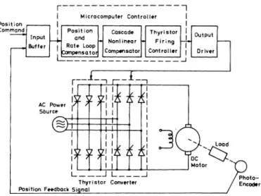
The schematic diagram of the dc servo system based on a
single-chip microcomputer is shown in Fig. 1. The three-phase
full-wave thyristordual converter is composed oftwelvesilicon
Manuscriptreceived April 21, 1981; revised March 9, 1982. P. C. Tang is with the Institute of Electronics Engineering, National
ChiaoTung University,Hsinchu, Taiwan, Republic of China.
S.S.Luis with theDepartment of Mechanical Engienering, National TaiwanUniversity,Taipei, Taiwan, Republic of China.
Y. C.Wu is with the Department of Control Engineering, National
ChiaoTung University, Hsinchu,Taiwan,Republicof China.
ji I, I; ~ > Load
II
j otorL..._W L___
Thyristor Converter itionFeedbackSignal
Fig. 1. Block diagram of the position servo system.
controlled rectifiers(SCR's). This converterisused to drive a
separately excited dc motor in a four-quadrant operation. The motor field is maintained constant. One incremental
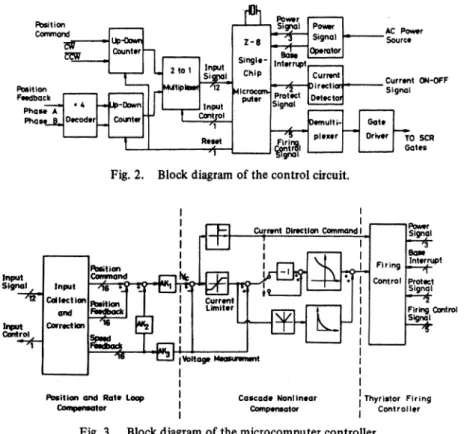
photoencoderis coupled to themotor shaft as the only feed-back transducer. Two-phase outputs of the photoencoder are used to generatethe position and the derived-speedfeedback. Uponreceiving the pulse-train-like command, this control cir-cuit will control both speed and position of the thyristor-driven dc motor. The block diagram of this fully digital
circuitisshowninFig.2 anddescribedbelow. A. Input Buffer
Input buffer functions as the interface among command,
photoencoder, and the single-chip microcomputer. For the purpose oftracking-system applications, command inputs are two pulse-train signals. One is the clockwise command and the other is thecounterclockwise command. By using three
divide-by-sixteen up-down counters, the position command is
obtainedby integrating these pulse-train signals.
Outputs of the incremental photoencoder are two-phase
pulse-train signals. The phase difference between them is
about
900.
After the multiply-by-four decoder, thesetwo-phase signals are decoded to clockwise and counterclockwise signals. Then, the position feedback is obtained by using the 12-bit up-down counter similar to the one used for position command. A microcomputer-controlled 12-bit two-to-one
multiplexer is used to read in the digitized position command and feedback. This multiplexeris desired in order to decrease thenumber ofmicrocomputerI/O required.
B.MicrocomputerController
The microcomputer used is
Zilog
Z8single-chip
micro-computer. The Z8 microcomputer introduces a new level of0278-0046/82/1100-0295$00.75 © 1982 IEEE
IEEETRANSACTIONS ONINDUSTRIALELECTRONICS, VOL. IE-29, NO. 4, NOVEMBER 1982
Fig.2. Blockdiagramofthecontrol circuit.
Position and Rate Loop cascade Nonlinear IThyristor Firing
Compwetor I Compensator I Controller
Fig.3. Blockdiagramofthemicrocomputercontroller.
sophistication
ofsingle-chip
architecture with 2Kbytes
ofinternal
ROM,
124bytes
ofon-chip
RAM,
twoprogrammable
8-bittimers, and 32 bitsofprogrammable
I/O.
The block
diagram
of themicrocomputer controller
isillustrated in
Fig.
3. Thefunctions
performed by
themicro-computer will be detailed in the next section. Becausemost
complex
works are executedby
microcomputer
software,thehardwaresarejustbuffersanddrivers. C
Output
DriverThe output driver functions as the interface between
the
thyristor
dual converter and thesingle-chip
microcom-puter. The design of the output driverisbased onthe workby
Tang,
Lu, and Wu[5].
Thethree-phase
ac sourcesignals,
digitized
by
using the powersignal
operator, are sent to themicrocomputer for
firing
control. In each600,
ofac source, the base interrupt signalis generated at each zerocrossing
of the three-phase ac source. This signal is used tosynchronize
themicrocomputer andacsource.The current direction detector is used to detect the
bi-direction current ON-OFF signals. These ON-OFF
signals
are sent tothemicrocomputer
forcrossoverdamage
protectionofthyristordual converter.
The
demultiplexer
andthegatedriverareusedtodistributethe SCR
firing
signals to each gate of chosen SCR's. These SCRfiring
signalsare generatedby
themicrocomputer under the control of afiring
controlsoftware.III.SOFTWAREDESCRIPTION
Most functions of the servo controller are performed by the microcomputer software. As shown in Fig. 3, there are
three main tasks in the microccomputer software
which
in-cludes position and
rate-loop
compensation,cascade nonlinearcompensation,andthyristor
firing
control.A.Position and
Rate-Loop
Compensation
The
position
and rate-loop compensator compares theposition
command and feedback, then generates avoltage
command VC as its output. The first important job is to
obtain the correct position, command, and feedback. Be-cause the
length
ofhardware counterisonly 12bits, theover-flow of counter
happens
frequently. To correct theoverflow errorofthe counter,the foLlowing
code correctiontechnique
isused.
Due to the
frequency
response ofthephotoencoder,
it is assumedthat theinput signal frequency
is less than 700kHz.
In one
period
of360-Hzsamplingtime,themaximumnumberintegrated by
thecounterisless than 2047 pulses,which can be handledby
an 11-bit counter. Thus, the remaining bit in the 12-bitcounterisusedtocheck theoverflow of 11-bit data,and the software counter can then be constructed by
inte-grating
these overflows. In thisway,
the 16-bit position com-mand and feedback are constructed by combining the 4-bit softwarecounterandthe12-bithardwarecounter.By differentiating
the position feedback, the speed feed-back is obtained for rate-loop compensation. Due to the linearrelationship
between themotorspeed and the inducedEMF,
the speed signal canbe usedasthevoltage measurementby
multiplying a gain constantAK3. The other twoparam-eters, AK1 and
AK2,
are used to construct a proportionalcontrollerwith innerrate
loop.
B. CascadeNonlinearCompensation
The cascade nonlinear compensation is based on the design
by Tang,
Lu,
and Wu [4]. Using the difference between the voltage command and voltage measurement as a new param-eter, the firing-angle command is obtained by searching twotables. One isusedtogetthefiring angle underthe continuous current mode and the otheris used tomodify thisfiringangle 296
TANG et al.: DESIGNANDIMPLEMENTATIONOFSERVO-SYSTEMBASEDON A MICROCOMPUTER
External
Torque Cowmrand
Input
Fig.5. Linear modelofthepositionservo.
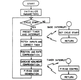
Fig. 4. Flow chart of themicrocomputercontroller. underthe discontinuouscurrent mode. In addition to the com-pensation ofnonlinear and loadingeffect in thethyristordual converter, the difference between the voltage command and voltage measurement canbe limited toasafe regionsothatit
functions as a current limiter. The sign of this voltage
dif-ference is also used asthecurrent direction command forthe
thyristor dual converter. Thus, the cascade nonliner compen-sation software computes the thyristorfiring angle and
direc-tion commands used for thethyristor firingcontrol.
C Thyristor FiringControl
This controller is based on the design by Tang, Lu, and
Wu [5]. The flowchart is shown in Fig. 4. The control cycle has a period of about 2.7 ms and is synchronized with the
ac source. At the start ofeach control cycle,the firing-angle
command calculated in last control cycle is used to set the delay time of thetimer, then the microcomputer proceedsto
calculate the next firing angle command. When the timer
counts down to zero, a signal is generated to interrupt the main process, and the SCR firing signals are sentto fire the chosenSCR's.
IV. SERVO SYSTEM DESIGN
The overall system is a nonlinear, sampled-data control
system. The sampling rate is 360 Hz and the maximum de-lay time including computing time and firing delay is two
sampling periods, about 5.5 ms. The exact analysis of the overall system is difficult, but the approximate solution is simple [4]. Because the system time constantis muchgreater
than the sampling periodanddue to thelinearizationeffect of the cascade nonlinear compensation, the overall system can
be approximated to a linear and continuous control system.
Thus, most of the design methods based on the linear and
continuous control theory can be applied to this micro-computer-based dcservosystem.
One ofthe simplest methods usedis aproportionalcontrol
with inner rate loop, as shown in Fig. 5. The step-by-step
design from inner loop to outer loop is chosen tosolve this problem. In the experiment, the motor used is a 0.5-kW
permanent magnet dc motor (90 V, 15 A, 3000 rpm). The only feedback transducer is a photoencoder with 2000 ppr.
With a 200-V peak-to-peak ac source and the parameters
AKl,
AK2,
andAK3 set at0.039,5.45,and0.98,respectively,theopen-loop gainis
43.3/s.
V.EXPERIMENTALRESULTS ANDDISCUSSIONS
Theopen-loopstep response of the uncompensatedthyristor
dual converter is shown in Fig. 6(a). Because of the semi-conductor characteristics of SCR's, no decelerating torque is applied to the motor during the transcience from high speed to low speed. The settling times in each transcience of ac-celeration and deac-celeration areapproximately 220 ms and 660 ms, respectively. With the use of the cascade nonlinear com-pensator, the transient response is improved in both tran-sience of acceleration and deceleration. The settling time of compensated thyristor dual converter is about 160 ms for both acceleration and deceleration, as shown in Fig. 6(b). In the experiments, the current limiter in the cascade nonlinear compensator is set at about 5 A to show its effect. As is evident from Fig. 6(b), both theacceleration anddeceleration are limited by this current limiter. If theopen-loopcommand change is so small that the current limit does not occur, asin the case ofFig. 6(c), the transient response are very fast and the same for both acceleration and deceleration. The settling time inthis case is about 40 ms.
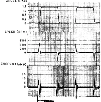
As can be seen fromFig. 6, thebenefitofthecascade non-linear compensation is obvious. With the use of the cascade nonlinear compensation, the step responses of the rate loop and the position loop are showninFigs. 7and8, respectively. The settling time of the rate-loop response andthe
position-loop response are about 80 ms undertheconditionofcurrent limiting. The transient responses are the same in both direc-tions. Because only a simple proportional controller is used
for the rate loop,there is some steady-state error in the
rate-loop
response,asshowninFig.7.For atype-1 controlsystem,
nosteady-state error exists in the response of position loop if there is no external torque.
The memory used in this system is about 1.4K bytes and
the maximum computing time in one control cycle is about 1.5 ms, as shown in Table I. In most servo control systems, some complex controllers are usually used to achieve the
higher performance, such as a lead-lag compensator, a PID controller, or a second-order compensator. The on-line
cap-ability in the microcomputer used in this system is so small that a morecomplexcompensator can also beimplemented.In
addition, the fully digital organization and microcomputer software control make it easy to link this system with other microcomputer systems. Thus, this system can be part of a computer network for adaptive control, automatic testing, automatic design, or other processes for industrial application needs.
IEEETRANSACTIONSONINDUSTRIAL ELECTRONICS, VOL. IE-29, NO. 4, NOVEMBER 1982 ANGLE(RAl 1. 1. 0. 0. SPEED (RPM 60 4 01 2 0 CURRENT(AMF D1) .6 .8 4 0
4,
I
t
-t'. t 44.-
t_..."L.--I';.. L;:1.,
-KL[
''_
II,
. 0oOr 1[1htli-; -L Jg8__ _ . I|XI § - .: 41 !,!,1 |s |lti !,,-I-...t*I t ) 1 5 10 S 0I I
II
,E .-I
Fig. 8. Step responseofposition loop;positioncommand from 0 rad
to1.57 rad.
TABLE I
LIST OF MEMORYANDTIME USED (b) 1200 800 400 0k I. .{t' 'It, Ut!["t K r lfl 1t-jt'!: (c)
Fig. 6. Stepresponseofthecompensatedthyristordualconverter with dc motor. (a) Without cascade nonlinearcompensator; firing-angle command from 1000 to 60°. (b) With cascade nonlinear
compen-sator; voltage command from 6 V to 70 V. (c)With cascade
non-linearcompensator;voltage commandfrom12Vto24 V.
Fig. 7. Step response of rate loop; rate command from 180 rpmto
1400rpm.
memory used(kbytes) time used(ms)
position and rate compensation 0.41 1.05
cascode nonlinear compensot ion 0.52 0.1
(including tables)
thyristor firing control 0.2 0.4
(including tables)
initialization program 0 27
total 1.4 1.55
z8 provided 2.0
sampling period 2.77
reserved for futureuse 0.6 1.22
VI.CONCLUSION
The quasi-linearization effect of a compensated thyristor
dual converter based on the principle of cascade nonlinear
compensation proposed by Tang, Lu, and Wu is confirmed by the experiment. Also, the equivalent effect of current
limitingispossiblethrough software control without usingany
currentfeedback.
With minimum hardware and good performance, this single-chip microcomputerdesignissuitable forafast-response
high-power dcservosystem forindustrialcontrol.
REFERENCES
[ ] T. Ohmaeetal.,"Amicroprocessor-controlled fast-responsespeed
regulator with dual-mode current loop for DCM drives," IEEE
Trans.Ind.Appi., vol. IA-16, pp. 388-394, May 1980.
[2] Y. T. Chanetal.,"AMicroprocessor-based currentcontrollerfor
SCR-DC motor drivers," IEEE Trans. Ind. Electron. Contr.
In-strum., vol. IECI-27, pp. 169-176, Aug. 1980.
[3] J. B. Plantetal., "Microprocessorcontrolofpositionorspeedof
an SCR-DC motor drive:' IEEE Trans. Ind. Electron. Contr.
Instrum., vol. IECI-27, pp. 228-234,Aug. 1980.
[4] P. C. Tang et al., "A cascade nonlinear compensation of the
thyristor dualconverterfor DCmotordrives," tobe published. [5] P. C. Tangetal., "Microprocessor-based design ofafiring circuit
forathree-phase full-wave thyristor dualconverter," IEEETrans.
Ind. Electron., vol. IE-29, pp. 67-73, Feb. 1982.
SPEED(RPM) SPEED (a) CURRENT F'7 I...I ,,.
JItL-V2
t .I..., ,Wn
SPEED(RPM) CURRENT(AMP)I5
101
'-iF
L.:;
.'" F I.,I'.-..-..]1. 1. 1 1::. .. 4 I Its. !., .. -LL-.1 ., kw"-,._.. ...S --! _ _,X .,..z I .i 298tii-i"II.;--
!-I '. Li .1