Nano-photonic Boxes to Modify Black-body Radiation for Visible
Light Emission
Cha-Hsin Chao
a, Cen-Shawn Wu
a, Ching-Fuh Lin
*a,ba
Graduate Institute of Electro-Optical Engineering
b
Graduate Institute of Electronics Engineering and Department of Electrical Engineering
National Taiwan University, Taipei, Taiwan, ROC.
ABSTRACT
The fabrication of metallic photonic boxes and their emission properties with black-body radiation at high temperatures are reported. Black-body radiation is modified to enhance the visible spectrum using photonic boxes of about 200 nm. With the structure of resonant cavity and the significantly enhanced density of states at specific wavelengths, the enhanced blue light is observed and it has the peak intensity at 400 nm with 90nm spectral width. Other visible spectra can also be enhanced by simply increasing the size of photonic boxes. Due to the high temperature operation, formation of metallic grain on the surface of photonic boxes is also discussed.
Keywords: Black-body radiation, photonic boxes, visible spectrum, illumination efficiency, resonant cavity, density of
states..
1. INTRODUCTION
Energy consumption has been being increasingly important to human beings nowadays. How to Increase illumination efficiency is very attractive for the concern of energy consumption. Nevertheless, the illumination efficiency remains low because the visible spectrum of black-body radiation at 2500K occupies only 5% of the total radiation energy. 1 Most energy emits in the infrared region that makes it difficult to have a desirable visible light emission at low temperature.
State-of-the-art research on photonics crystal offers the possibility to modify black-body radiation for the enhancement of emission in infrared spectrum. 2-6 However, enhancement in visible spectrum using photonic crystals has not been deeply explored yet. In addition, the physics of the enhancement is still not well understood due to the complication of photonic crystals. Here we report that the metallic photonic boxes structure can enhance black-body radiation in the desired visible spectrum range. Black-body radiation is modified to enhance the visible spectrum using photonic boxes of about 200 nm. The enhanced blue light has the peak intensity at 400 nm with 90nm spectral width. The spectral width is governed by the variation of the box size and it can be controlled by fabrication condition.
The metallic photonic box is just like a resonant cavity. The electromagnetic (EM) waves oscillate in the metallic cavity and then emit from the thin top metal, so we can easily design different box sizes for different wavelengths. In addition, spectrum of black-body radiation will be suppressed in long wavelength range because wavelength longer than cut-off wavelength cannot exist in a resonant cavity, just analogous to the band gap of photonic crystal. The photonic boxes have an infinite band gap for wavelength longer than the cut-off wavelength. In addition, we can only see narrow range spectrum with particular modes of wavelengths. As a result, light intensity in the visible light band is enhanced several times.
Due to the high temperature operation during the experiment, we observe that there are some metallic grains formed on the surface of the photonic boxes. Top metal thin layer is to cover the photonic boxes to make EM waves resonate inside it. Although the topology of the top layer won’t change the property of the photonic boxes, it still has some influence. The thick metallic grain will block some part of radiation emitted from the photonic boxes. The surface treatment of the metallic photonic boxes is also discussed in this work.
The physics of visible-light enhancement photonic boxes can be easily explained by the significantly enhanced density of states (DOS) at a certain spectrum as a result of photonic boxes. Total radiation of the photonic boxes can be regarded as having two components. One is the photonic boxes themselves, the other is the surrounded metal which
* E-mail: cflin@cc.ee.ntu.edu.tw
Photonic Crystal Materials and Devices IV, edited by Ali Adibi, Shawn-Yu Lin, Axel Scherer, Proc. of SPIE Vol. 6128, 61281N, (2006) · 0277-786X/06/$15 · doi: 10.1117/12.645346
= •7=•, Sicinal A InLens
200 nm photoresist
metal dielectric
silicon
corresponding to the conventional black-body radiation. 7 The DOS of the photonic boxes can be simulated with Gaussian functions, which have the center wavelengths calculated with the theorem of the EM resonant cavity. Thus we can get the radiation energy and the radiation spectra of the photonic boxes at different temperatures.
As a result, light intensity in the visible light band is enhanced several times. No complicated materials corresponding to different visible light are needed, showing a great advantage over visible LED or OLED.
2. FABRICATION PROCESS
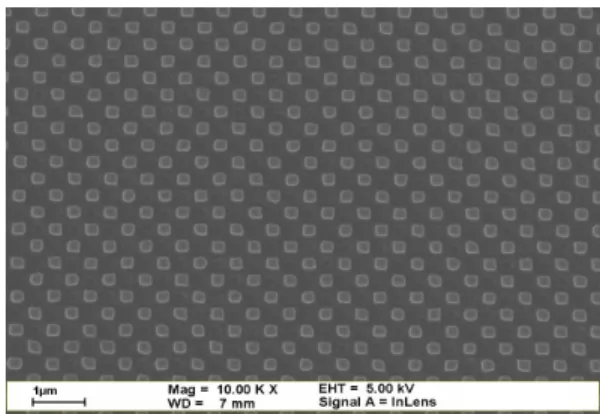
A schematic diagram of designing the metallic photonic boxes is illustrated in Fig 1. The metallic photonic box here is defined by a dielectric box surrounded by metal outside. The fabrication procedures are described as follows. First, metal Cr/Au/Pt with the thickness of 10 nm, 20nm, and 100 nm was sequentially evaporated on the Si substrate, respectively. Spin-on glass (SOG) was then spun on top of the Pt metal with 6000 rpm rotation speed. Then the sample is cured at 175°C, 275°C and 475°C with 1min, 1min and 40min time period by rapid thermal annealing (RTA), respectively. After the thermal treatment, this SOG layer has a thickness of 220 nm and the refractive index of 1.4. Afterwards, photoresist (PR) was spun on the SOG. Immersion interference photolithography (IIPL) using a 351 nm Argon ion laser was applied twice to create two dimension periodic patterns on the PR. The patterned PR is supposed to consist of many periodically aligned 220 nm x 220 nm squares and pitch of the pattern is 500nm, as shown in Fig 2. However, because it is not possible to accurately define 220 nm features using UV lithography, the actual shapes are different from square. The patterned PR was used as the mask in the reactive-ion-etching (RIE) process. We have also tried to use E-beam lithography do define more exact pattern. During RIE, Ar and CHF3 gases were used to remove the SOG uncovered by PR. Before the removal of PR, platinum was evaporated to fill up the area where the SOG was etched. The desired thickness of platinum is 220 nm, same as the thickness of SOG. Then PR was rinsed off by acetone, so Pt on top of the PR was also removed. The imperfect fabrication process results in slightly changing the shape of the photonic boxes, as shown in Fig 3. However, because most boxes still have Pt surrounding the dielectric, the function of the photonic boxes is still preserved. The processing was completed with the last step of depositing 10 nm Pt layer using evaporation. The top Pt layer is made only slightly thicker than its skin depth (~6 nm) such that the resonant EM wave in the dielectric of the photonic boxes can leak out.After the fabrication, many photonic boxes are formed. The interior of the photonic boxes is the dielectric of SOG and the surrounding wall is Pt metal.
Fig. 1: Schematic diagram of designing the metallic photonic boxes.
Fig. 2: SEM image of photoresist pattern made by Immersion Interference PhotoLighography (IIPL).
— w — - — — — ?
— — — — — —
_
-- _
__ — dUS —
4 — — — — —
—
L —
— —
Lock-in Amplifier SRS SR830 Vacuum heater lens Monochromater CVI CM110 PMT High-V source chopper computer irisFig. 3: SEM image of the topology of the photonic boxes after lift-off process.
3. EXPERIMENT RESULTS
3.1 Measurement setups
In order to prevent oxidization during the high temperature operation, we put the sample in a vacuum chamber with pressure near 5x10⁻⁴ Pa. The temperature can approach 1800K, determined by a thermal couple (see Fig 4). When the sample is heated on the graphite boat, according to the Planck’s Law of Blackbody Radiation, we can observe that the graphite boat appears white-hot and heat will be conducted to the sample. The heat transfer efficiency is governed by the smoothness of contact surface between the sample and the heater. Light will propagate upwards and be reflected by a mirror placed obliquely in the chamber in order to direct light toward the monochromator. The light path is specially designed so that only the light emitted from the sample surface will be focused on the inlet of monochromater by a lens. We adjust the position of the lens to make the image form just right on the entrance of the monochromater CVI CM110. The PMT is used behind the monochromater for light detection. The response range of the PMT is from 200nm to 900nm. Lock-in Amp SRS SR830 is connected with PMT and triggered by an optical chopper MC1000. Finally, the signal is transferred to computer for the spectrum measurement.
Fig. 4: Schematic diagram of measurement setup.
3.2 Measurement results
Blackbody radiation spectrum is governed mainly by temperature, described as the Planck’s Law, ) 1 ( 2 ) , ( 5 / 2 − = hc kT e hc T E λ λ π λ (1)
4000 5000 6000 7000 8000 9000 0.000000 0.000002 0.000004 0.000006 0.000008 0.000010 0.000012 0.000014 0.000016 0.000018 0.000020
with box structure without box structure
Metallic Photonic Box Blackbody radiation spectrum
Wavelength (A) Intens ity (a. u .)
where h is Planck’s constant, c is the speed of light, λ is the wavelength, k is the Boltzmann’s constant. Usually conventional black-body radiation emits mainly in visible light range only when the temperature exceeds 5000 K. However, we can make use of properties of cut-off wavelength of metallic photonic resonant box to suppress long wavelength range. Cut-off wavelength is given by
2 2 2 2 m l k na klm + + =
λ
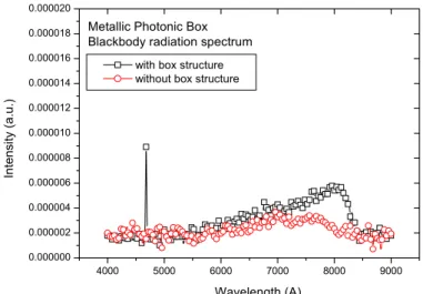
(2) where n is refractive index, a is box length, and k, l, m are EM wave modes. For instance, when a = 200 nm and refractive index = 1.4, we obtain cut-off wavelength λ = 410 nm, corresponding to blue light. Wavelengths longer than this cannot exist, thus forming an infinite forbidden photonic band gap, analogous to the terminology for photonic crystals. 8 In addition, there are many band gaps between resonant modes calculated by equation (2).Enhanced blue light signal at 467nm as a result of metallic photonic boxes is firstly observed, as shown in Fig 5. The sample is heated at 950K. With box size of 220nm, the cut-off wavelength can be calculated to be 467nm from previous derivation. The peak is enhanced by approximately 5 times compared with the reference spectrum which shows no enhanced signal in the visible range. The long wavelength also appears property of suppression due to the infinite band gap of photonic box. During the experiment, we also observe that the surface topology of the photonic boxes will change with the long-period high temperature operation. The detailed heating issue will be discussed in next section.
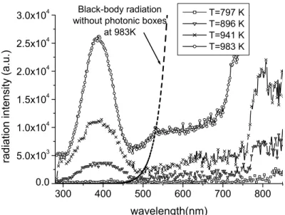
Other enhanced peak is also obtained with the fabricated box size of 200nm. Another fabricated sample shows a measured peak near 400 nm with a narrow spectral width at temperatures 797K to 983K, and long-wavelengths range are suppressed greatly, as shown in Fig 6. The peak is amplified by approximately 6 times larger than background level in the 500 to 600nm range. At the temperature of 983K, the peak intensity at 390 nm is about 5 times larger than the background level at 470 nm. The slightly reduced contrast is due to the fact that the photonic boxes are partially destroyed. The reason is two-fold. First, because the top layer of Pt is only about 10 nm, this Pt film might form metallic grains at high temperature. Secondly, the substrate Si and metals Cr, Au, and Pt might form alloys at high temperature. Then the photonic-box structures are reshaped. Using materials that sustain high temperature might improve the operational situation.
The spectral width is 90 nm, which is about the same for all temperatures. This is another important feature characterized by the DOS function of the photonic boxes. It is due to the size variation of the photonic boxes resulting from the imperfect fabrication process. The temperature-independent behaviors are different from those in the usual black-body radiation, but similar to the behaviors of metallic photonic crystals. However, the emission peak and the spectral width of the black-body radiation of the metallic photonic crystals are due to the periodic nature. 9In comparison, with photonic boxes, the black-body radiation has the peak wavelength located at the resonance wavelength of the largest-number boxes and the spectral width governed by the size variation. If the photonic boxes have a single size, we expect that the emission should have a very narrow line. Our investigation of photonic boxes gives a much clearer explanation on the physics of the black-body radiation modified by photonic structures.
Fig. 5: Black-body radiation spectra of metallic photonic boxes. The box size is 220nm.
200 300 400 500 600 700 800 900 1000 0.000 0.002 0.004 0.006 0.008 0.010 0.012 0.014
0.016 Metallic Photonic Box Blackbody radiation spectrum (SiO2 pillar) Inten sity (a .u .) Wavelength (nm) T=900K 300 400 500 600 700 800 0.0 5.0x10³ 1.0x10⁴ 1.5x10⁴ 2.0x10⁴ 2.5x10⁴
3.0x10⁴ without photonic boxesBlack-body radiation
at 983K T=797 K T=896 K T=941 K T=983 K rad iat ion in tensity (a.u.) wavelength(nm)
Fig. 6: Black-body radiation spectra of metallic photonic boxes. The box size is 200nm.
Except fabricating the photonic boxes buried inside the metal, we also try to fabricate another type of photonic boxes, we called it pillar type photonic boxes. The fabrication process is similar to those described in section 2, but the dielectric layer is not deposited first. After evaporating metal layer on Si substrate, lithography is directly used to create 2D periodic pattern on metal. Next SiO2 is evaporated and then lifted-off together with the photoresist remained after the lithography. Finally we evaporate obliquely twice to cover the bulgy photonic boxes. However, this kind of photonic boxes suffers from the disadvantage of instability due to lack of surrounded thick metal wall. It can only be operated shortly or the metal film covered outside the box will regroup. The black-body radiation spectrum of pillar type photonic boxes is also observed, as shown in Fig 7.
Fig. 7: Black-body radiation spectra of pillared metallic photonic boxes. The box size is 250nm.
3.3 Heating issue
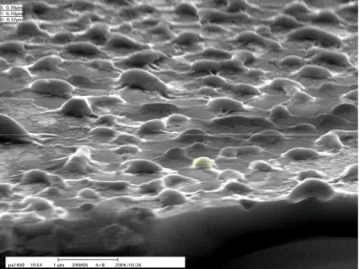
The surface topology of the photonic boxes is inevitably changed during long-period high temperature operation. In our structure, the top layer is the thin metal film that is to cover the photonic boxes. We observe there is a topological change when the temperature exceeds about 750K, as shown in Fig 8. The size of the metallic grain varies from 200nm
to 1000nm. The melting point of the platinum is 2041K, which is still higher than the operation temperature. The reason can be conjectured that thin metallic film at high temperature will somehow regroup into favorite shape as a result of offered energy. However, the top topology won’t change the property of the photonic boxes. It only has some influence on blocking some part of emitted light from the photonic boxes. It can be solved by using materials which has much higher melting point, or we can evaporate dielectric layer on top of it to prevent the top layer from changing to metallic grains.
Fig. 8: SEM image of surface topology after high temperature operation.
4. THEORETICAL ANALYSIS
If a body consists of many photonic boxes that do not have the same size, the resonance wavelengths will form a band with its density of states undulated by the size distribution function. Then the band gap between the resonance peaks shrinks and may disappear if the size distribution function is broad. However, the widest band gap that extends from the largest cut-off wavelength (corresponding to the largest box) to infinite wavelength should still exist. The cases of a unique size and various sizes have been investigated theoretically. On the other hand, the photon statistics that favors long-wavelength spectrum 10 will cause the DOS at the cut-off wavelength to dominate light emission. That is why metallic photonic boxes are designed for visible light enhancement. Our theoretical investigation shows that the photonic boxes have much stronger effect on the visible range than the infrared spectrum.
Because the photonic boxes are surrounded by metals, the emission of light consists of two parts: the EM wave in the photonic boxes and the other part from the surrounded metal. The part from the surrounded metal is still governed by the conventional black-body radiation. Therefore, the total radiation is given by
dv e hv v c V v g V dv v) P P( ) C 83 2 hv/kT ( ⎟⎟ ⎠ ⎞ ⎜⎜ ⎝ ⎛ + π = µ
(3)
where the first part in the right hand side describes the radiation from the photonic boxes and the second part describes the radiation from the surrounded metal; gp(ν) and gc(ν) are the DOS functions (per unit volume) for the first part and the surrounded metal, respectively; Vp and Vc are their corresponding total volumes, respectively; nsis the photon statistics.
Gp(λ) or gp(ν) can be simulated with a Gaussian function, describe as follows
( ) [ ]
(
)
2 2 693 . 0 , # ) ( 02 FWHM a e a g a p = = − − λ λ π λwhere a is a normalization constant.
0.00100 0.00105 0.00110 0.00115 0.00120 0.00125 102 103 104 slope = -1.9767*104 983K 941K 896K 797K Temperature-1 (1/K) Pea k In te ns ity (a .u .)
Peak intensity vs reciprocal temperature
300 400 500 600 700 800 0 5000 10000 15000 20000 25000 30000 35000 40000 7340 78008260 T=797 K T=896 K T=941 K T=983 K
theoretical fitting with T=983 K
In te n sity (a .u.) Wavelength (nm)
For comparison, the conventional black-body radiation at 983K is also plotted in Fig 9. Its intensity near 400 nm is much lower than the long-wavelength range. The photonic boxes enhance the blue light and meanwhile suppress the long-wavelength radiation, leading to the enhancement of the blue light relative to the long-wavelength spectrum. The spectral width is 90 nm, which is about the same for all temperatures. The spectral width is caused by the size variation of the photonic boxes due to the fabrication variation of UV lithography to pattern the photoresist. However, the spectral width does not vary with the temperature. This behavior is different from the usual black-body radiation, but is similar to the behavior of metallic photonic crystals. The emission peak and the spectral width of metallic photonic crystals are caused by the periodic nature. In contrast, the peak wavelength of the photonic boxes is pinched at the resonance wavelength of the largest-number boxes and the spectral width is governed by the size variation. If there is no size variation, i.e., photonic boxes have a unique size, the emission line should have a laser-like behavior. We also make the comparison with the peak intensity versus various reciprocal temperatures, shown in Fig. 10. According to the Planck’s law of radiation, the radiation intensity has the relation as follows
1 1 − ∝ kT hc e E λ
If we take natural logarithm on both sides, we can find the slope in the semi-log plot which corresponds to the emitting wavelength.
Fig. 9: Measured spectra of radiation at different temperatures and theoretical fitting with formula (3) at T=983K.
Fig 10: The peak intensity versus reciprocal temperature.
The peak wavelength remains at approximately 390 nm at those temperatures, which is an important feature resulting from the DOS function of the photonic boxes, as described by equation (3). For temperatures not above 941K, the peak intensity at 390 nm is about 6.5 times larger than the background level at around 470 nm, shown in Fig. 9. Assuming that the background level is the black-body radiation with the DOS function gp(ν) of the photonic boxes equal to zero, we have the following relation
( )
1 8 5 . 6 1 8 2 1 2 2 2 3 1 2 1 3 1 − × ≅ − ⎟ ⎠ ⎞ ⎜ ⎝ ⎛ + kT h c kT h c p p e h c V e h c V g V ν πν νν πν ννwhere ν1 and ν2 are the frequencies corresponding to the wavelengths of 390 nm and 470 nm, respectively. Because 1 8 1000 1 8 1 2 1 2 1 3 2 2 2 3 − × ≥ − kT h c kT h c e h c V e h c V πν νν πν νν
for those temperatures, we have
( )
c hv kT C hv kT p p e hv v c V e hv c V g V 2 /1 1 3 / 1 2 1 3 1 1 8 6500 8πν π ν ⎟ > × ⎠ ⎞ ⎜ ⎝ ⎛ +Therefore, the emission at 390 nm is 6500 larger than the conventional black body radiation.
5. CONCLUSIONS
In conclusion, we demonstrate the enhancement of black-body radiation at the visible spectrum. For photonic boxes with a size of about 200 nm, the enhanced blue spectrum has a peak at 390nm and a spectral width of about 90 nm. The higher the temperature we apply, the stronger the intensity at the peak wavelength is. Because the long-wavelength radiation is suppressed, the peak intensity at 390nm could be 6.5 times larger than the background level at around 470 nm. In contrast, the conventional black-body radiation has its radiation intensity at 390 nm weaker than the intensity above 470 nm for over 1000 times. With the same concepts, other wavelengths can be obtained with different dimension of the metallic photonic boxes for various applications. As demonstrated by another type of photonic boxes, the peak emission wavelength is about 510 nm.
If the box has other shapes, for example, cylindrical shape or other geometric shapes, we can also analogously apply EM theory to calculate its resonance wavelengths. Their characteristics of appearing cut-off wavelength and suppressing long-wavelength spectrum are similar to those of the cubic photonic box
ACKNOWLEDGEMENTS
The authors acknowledge the support from National Science Council, ROC under the contract NSC94-2120-M- 002-010 and NSC 94-2112-M-002-009.
REFERENCES
1. O. Theimer, “Derivation of the Blackbody Radiation Spectrum by Classical Statistical Mechanics”, Phys. Rev. D, 4, 6, 1597~1601 (1971)
2. S. Y. Lin, E. Chow, V. Hietala, P. R. Villeneuve, J. D. Joannopoulos, “Experimental demonstration of guiding and bending of electromagnetic waves in a photonic crystal” Science 282 (5387): 274 OCT 9 (1998).
3. T. Baba, N. Fukaya, and J. Yonekura, “Observation of light propagation in photonic crystal optical waveguides with bends” Electron. Lett. 27, 654 (1999).
4. S. Noda, A. Chutinan, and M. Imada, “Trapping and emission of photons by a single defect in a photonic bandgap structure” Nature 407, 608 (2000).
5. S. Y. Lin, J. Moreno, and J. G. Fleming, “Three-dimensional photonic-crystal emitter for thermal photovoltaic power generation” Appl. Phys. Lett. 83, 380 (2003).
6. M. U. Pralle, N. Moelders, M. P. McNeal, I. Puscasu, A. C. Greenwald, J. T. Daly, E. A. Johnson, T. George, D. S. Choi, I. El-Kady, and R. Biswas, “Photonic crystal enhanced narrow-band infrared emitters” Appl. Phys. Lett. 81, 4685 (2002).
7. C. F. Lin, C.H. Chao, L.A. Wang and W.C. Cheng, “Black-body radiation modified to enhance blue spectrum.”, JOSA B, Vol. 22, issue 7, p.1517-1520 (2005)
8. J. G. Fleming, S. Y. Lin, I. El-Kady, R. Biswas and K. M. Ho, “All-metallic three-dimensional photonic crystals with a large infrared bandgap” Nature 417, 52 (2002).
9. S. Y. Lin, J. G. Fleming, E. Chow and J. Bur, “Enhancement and suppression of thermal emission by a three-dimensional photonic crystal” Phys. Rev. B 62, R2243 (2000).
10. F. Reif, Fundamentals of Statistical and Thermal Physics, McGraw Hill, 1965.