IEEE SIGNAL PROCESSING LETTERS, VOL. 10, NO. 12, DECEMBER 2003 349
Data Hiding in Halftone Images With Noise-Balanced
Error Diffusion
Soo-Chang Pei, Fellow, IEEE, and Jing-Ming Guo
Abstract—In this letter, we propose a low-complexity algorithm for embedding watermark into two or more error-diffused images. The first one is only a regular error-diffused image, and the others are achieved by applying the proposed noise-balanced error diffusion technique (NBEDF) to the original gray-level image. The visual decoding pattern can be perceived when these two or more similar error-diffused images are overlaid each other. Fur-thermore, with the proposed modified version of NBEDF, the two halftone images can be made from two totally different gray-tone images and still provide a clear and sharp visual decoding pattern. Index Terms—Digital watermark, error diffusion, halftone, least squares, ordered dither.
I. INTRODUCTION
D
IGITAL HALFTONING [1] is a technique for changing multitone images into two-tone binary images. The tech-nique is commonly used in computer printers, as well as printing books, newspapers, and magazines because these printing pro-cesses can only generate two tones, black (with ink) and white (without ink). There are several kinds of halftone methods, in-cluding ordered dithering, error diffusion [2], least squares [3], etc. Among these, error diffusion offers good visual quality and reasonable computational complexity.Data hiding have many usages, including protecting owner-ship rights of an image, protecting against the use of an image without permission, and authenticating an image to show that it has not been altered. Currently, numerous methods using halftones to embed watermarks have been studied, and they can be divided into two categories. These techniques can be used for printing security documents such as identification cards, currency, as well as confidential documents, and prevent illegal duplication and forgery by further scanning these documents to digital form.
Techniques of the first category embed invisible digital data into halftone images that can be retrieved by scanning and applying some extraction algorithms on the scanned image. These methods include using the concept of vector quantization (VQ) to embed watermarks into the most or least significant bit (MSB/LSB) of error diffusion images [4], using the technique of modified data-hiding error diffusion (MDHED) to embed data into error diffusion images [5], and data-hiding and
Manuscript received May 29, 2002; revised November 15, 2002. This work was supported by the National Science Council of Taiwan, R.O.C., under Con-tract NSC91-2219-E-002-044 and by the Ministry of Education under ConCon-tract 89-E-FA06-2-4. The associate editor coordinating the review of this manuscript and approving it for publication was Dr. Antonio Ortega.
The authors are with the Department of Electrical Engineering, National Taiwan University, Taipei 10617, Taiwan, R.O.C. (e-mail: pei@cc.ee.ntu.edu.tw).
Digital Object Identifier 10.1109/LSP.2003.817856
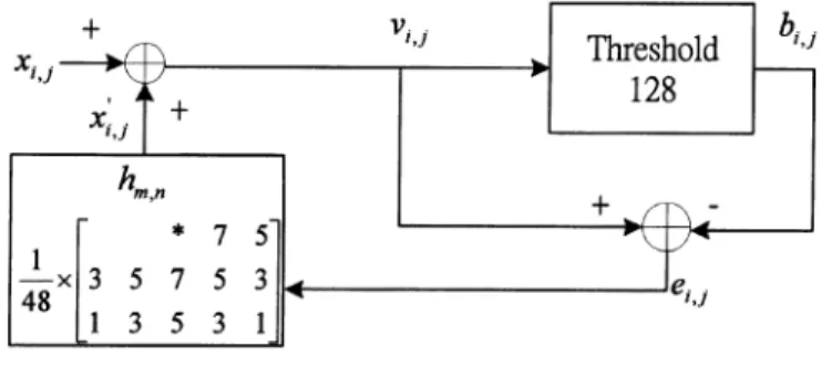
Fig. 1. Standard error diffusion flowchart.
authentication schemes based on halftoning and coordinate projection [6].
Methods of the second category embed hidden visual patterns into two or more halftone images. The hidden visual patterns can be perceived directly when the halftone images are overlaid each other. These techniques include using stochastic screen patterns [7], conjugate halftone screens [8], and stochastic error diffu-sion [9]. In [9], the concept of making a different phase verdiffu-sion of stochastic error diffusion image to achieve the data-hiding technique is adopted. However, poor contrast of the hidden pat-tern in the high texture region of error diffusion image is found. In this letter, we propose an algorithm that is similar in concept to threshold modulation [10] to solve this problem, and the com-putational complexity is kept relatively low.
II. DATAHIDINGWITHNOISE-BALANCEDERRORDIFFUSION
The encoding scheme used here is to embed the desired wa-termark into an error diffusion image, which we denote EDF2. The decoding scheme superimposes EDF2 with the original EDF image, known as EDF1, so the decoded watermark can be perceived directly from the two overlaid EDF images.
The standard EDF flowchart is shown in Fig. 1. Here we de-fine 255 as a white pixel and 0 as a black pixel. The variable means binary output in position . The variable is the modified gray output, and is the difference between the modified gray output and binary output . The relation-ships of , , and are described as follows:
where (1) where if if (2) 1070-9908/03$17.00 © 2003 IEEE
350 IEEE SIGNAL PROCESSING LETTERS, VOL. 10, NO. 12, DECEMBER 2003
We define as the set of locations of all the “white” pixels in the watermark and the set of locations of all the “black”
pixels. Similarly, EDF , EDF , EDF , EDF
are defined as above. If the processing position of EDF2
satisfies the conditions: and EDF ,
then it should be processed with the proposed NBEDF algo-rithm. Equations (1) and (2) should be modified as follows:
(3) (4) If the processing position of EDF2 satisfies the
condi-tions: and EDF , it still be processed
with standard EDF. If the processing position , the output of EDF2 is the same as that of EDF1. So in this case, EDF1 and EDF2 should be made from the same gray-level image.
If the variable in (3) and (4) is increased, the quality of EDF2 will degrade, while the decoded visual pattern will be-come clearer; the opposite will be true when the value of is decreased. Superimposing EDF1 and EDF2 reveals clearly the watermark black region. With the proposed NBEDF algorithm, we can generalize it to other applications as follows.
First, we can increase the number of EDF images to three or more, and the algorithm is similar to the one described above. Take the encoding of the watermark into three EDF images as an example. If the processing position of
EDF3 satisfies the conditions , EDF
and EDF , then it should be processed with
the proposed NBEDF algorithm. If the processing position
of EDF3 satisfies the conditions and
EDF or EDF , then it only needs to
be processed with standard error diffusion. If the processing position , the output of EDF3 is the same as that of EDF1. In general, when more EDF images are overlaid, the visual pattern will reveal better contrast. Sometimes the halftone image may suffer some distortions due to printing, dirt, and attack, etc., and the visual decoded pattern obtained by overlapping only two images may not be clear enough. The technique of superimposing more than two NBEDF images can improve this problem.
Second, EDF1 and EDF2 can be made from two totally different gray-tone images. Here, we should modify the NBEDF algorithm. Initially, should be expanded uni-formly by morphological dilation, as shown in Fig. 2. In this example, the dilation mask size is 3 3, and defined as in Matlab expression. If the pixel value of watermark in position is , the new pixel value processed with the 3 3 dilation mask is given by
if
if , or or or
if
(5) where represents the union process of elements in paren-theses. The dilation mask covers only a small portion of the watermark and processes with the concept of sliding window and orientated with raster scan. The gray region in Fig. 2(b) is
Fig. 2. Watermark processed with 32 3 morphological dilation.
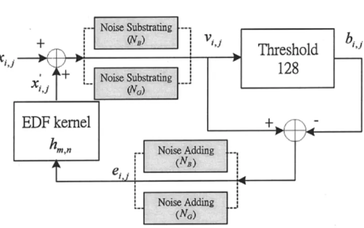
Fig. 3. Modified version of NBEDF flowchart.
obtained by dilation, and we define it as . If the processing position of EDF2 satisfies the conditions
and EDF , then it should be processed with the modified NBEDF algorithm, and (1) and (2) should be mod-ified as follows:
(6) (7) If the processing position of EDF2 satisfies
or , then the processing method is the same as NBEDF and the additive noise is . The modified NBEDF flowchart is shown in Fig. 3. When we overlay EDF1 and EDF2, the black pixels surrounding the visual pattern will be less than usual. With this strategy, we will obtain clearer and sharper vi-sual decoding patterns.
III. EXPERIMENTALRESULTS
The embedded watermark is shown in Fig. 4(a). A standard 512 512 pixel Jarvis EDF Lena image is produced, shown in Fig. 4(b). Fig. 4(c) shows the EDF image processed with the proposed NBEDF algorithm. The balanced noise used here is 5. The superimposed version of Fig. 4(b) and (c) is shown in Fig. 4(d). Fig. 4(f) shows the result achieved by superimposing by one standard EDF and two NBEDF images [Fig. 4(c) and (e)]. In Fig. 4(f), we find that the contrast of the visual decoding pattern is better than that in Fig. 4(d).
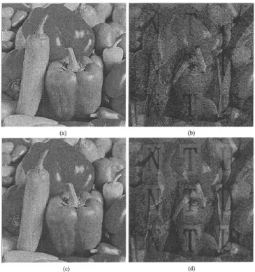
Fig. 5(a) shows the NBEDF Peppers image and Fig. 5(b) is the superimposed halftone version of Figs. 4(b) and 5(a). The addi-tive noise strength used in Fig. 5(a) is 15. Fig. 5(c) was achieved by processing the gray-tone Peppers image with the modified NBEDF algorithm, and Fig. 5(d) was achieved by overlaying Figs. 4(b) and 5(c). The values chosen here for and are 15 and 10, respectively, and the dilation mask size is 31 31. As seen in Fig. 5(d), the number of black pixels surrounding the visual pattern is obviously less than that in Fig. 5(b) to improve
PEI AND GUO: DATA HIDING IN HALFTONE IMAGES WITH NOISE-BALANCED ERROR DIFFUSION 351
Fig. 4. Images are printed at 150 dpi, and the sizes are equal to 5122 512. (a) The original watermark. (b) The original EDF Lena image. (c) The embedded Lena image.(N = 5). (d) The overlaid version of (b) and (c). (e) The second embedded Lena image.(N = 5). (f) The overlaid version of (b), (c), and (e).
contrast. Therefore, the visual decoding pattern in Fig. 5(d) is perceived as clearer and sharper than that in Fig. 5(b). We have also applied the NBEDF algorithm for superimposing Mandrill and Lena halftone images. Because the Mandrill is an image full of high texture, the masking effect is very strong. We found that although it is seamless in the border of watermark in NBEDF Mandrill image, the contrast of visual decoding pattern is lower than Fig. 5(d).
Note that the overlaid results shown in this letter are synthe-sized by computer. In practical experimental results, we find that it is hard to perfectly reveal the watermark when both images are printed on transparencies and overlaid. It is caused by several distortion factors in printing process, including rotation, trans-lation, scaling, and dot gain, etc. Some methods can be used to reduce these distortions, e.g., 1) put auxiliary synchronized pixels in four corners of the two overlaid images and 2) before printing, the two overlaid images can be enlarged in advance by computer. From the experiments, we have superimposed the two enlarged images with the aid of the synchronized pixels in four corners, the visual decoded pattern became clearer than the original one.
Fig. 5. Images are printed at 150 dpi, and the sizes are equal to 5122 512. (a) The embedded Peppers image(N = 15). (b) The overlaid version of Figs. 4(b) and 5(a). (c) The embedded Peppers image (N = 15, N = 10, dilation mask size= 31 2 31). (d) The overlaid version of Figs. 4(b) and 5(c) with improved contrast.
IV. CONCLUSION
In this letter, a data-hiding scheme is proposed with balanced noise for embedding the watermark. The embedded data could be decoded visually by superimposing the original EDF images and the NBEDF image. We also use the modified NBEDF for data hiding and the two EDF images can be made from two to-tally different gray-tone images. The experimental results show that the visual decoding pattern is still clear and sharp. Further-more, the computational complexity of this algorithm is kept relatively low.
REFERENCES
[1] R. Ulichney, Digital Halftoning. Cambridge, MA: MIT Press, 1987. [2] J. F. Jarvis, C. N. Judice, and W. H. Ninke, “A survey of techniques for
the display of continuous-tone pictures on bilevel displays,” Comput.
Graph. Image Process., vol. 5, pp. 13–40, 1976.
[3] M. Analoui and J. P. Allebach, “Model based halftoning using direct binary search,” in Proc. SPIE, Human Vision, Visual Proc., Digital
Dis-play III, vol. 1666, San Jose, CA, Feb. 1992, pp. 96–108.
[4] J. R. Goldschneider, E. A. Riskin, and P. W. Wong, “Embedded multilevel error diffusion,” IEEE Trans. Image Processing, vol. 6, pp. 956–964, July 1997.
[5] M. S. Fu and O. C. Au, “Hiding data in halftone image using modified data hiding error diffusion,” in Proc. SPIE Conf. Visual Communication
and Image Processing, vol. 4067, 2000, pp. 1671–1680.
[6] C. W. Wu, “Multimedia data hiding and authentication via halftoning and coordinate projection,” EURASIP J. Appl. Signal Process., vol. 2002, no. 2, pp. 143–151, Feb. 2002.
[7] K. T. Knox, “Digital watermarking using stochastic screen patterns,” U.S. Patent 5 734 752.
[8] S. G. Wang, “Digital watermarking using conjugate halftone screens,” U.S. Patent 5 790 703.
[9] M. S. Fu and O. C. Au, “Data hiding in halftone images by stochastic error diffusion,” in Proc. IEEE Int. Conf. Acoustics, Speech and Signal
Processing, May 2000.
[10] K. T. Knox and R. Eschbach, “Threshold modulation in error diffusion,”
J. Electron. Imag., vol. 2, no. 3, pp. 185–192, July 1993.