以ART平台為基礎的行動應用程式開發工具
56
0
0
全文
(2) 以 ART 平台為基礎的行動應用程式開發工具 ART-based Mobile Application Development Kit. 研 究 生:劉昀昇. Student:Yun-Sheng Liu. 指導教授:袁賢銘. Advisor:Shyan-Ming Yuan. 國 立 交 通 大 學 資 訊 科 學 系 碩 士 論 文. A Thesis Submitted to Institute of Computer and Information Science College of Electrical Engineering and Computer Science National Chiao Tung University in partial Fulfillment of the Requirements for the Degree of Master in. Computer and Information Science June 2004 Hsinchu, Taiwan, Republic of China. 中華民國九十三年六月.
(3) 以 ART 平台為基礎的行動應用程式開發工具. ABSTRACT IN CHINESE. 研究生:劉昀昇. 指導教授:袁賢銘. 國立交通大學資訊科學系. 摘要 ART(Adaptive Remote Terminal)是一個可適性的行動應用程式開發平台,它結合了 thin-client computing 和 mobile computing。從設計面來看,此平台能支援各種不同的手 持裝置,程式設計人員所開發的應用程式只要寫一次,就能夠在各種不同的平台上執 行,大大降低了開發與維護的成本;從應用面來看,程式設計人員在此平台上所開發出 來的程式可以利用 server 強大的運算能力與豐富的資源來達成一般手持裝置所無法執行 的功能。 在 ART 的架構中,client 端只賦予程式執行結果的呈現能力,邏輯運算全都置於 server 端,兩端的溝通是透過網路傳遞非同步訊息來達成。然而,現今的行動裝置執行 環境,無法使用或不便使用網路的狀況非常多,但是本身的運算資源,卻是越來越強大。 故在此篇論文所提供的開發工具中,設計一套廣泛適用的轉換工具,能夠將以 ART 平 台為基礎的應用程式自動的轉換至能獨立在 client 端執行的版本,讓使用者也能夠在不 需要網路的環境下執行它們。 此 篇 論 文 定 義 一 套 符 合 XML 的 轉 換 語 言 IM 2 L (Interface Mapping Markup Language),能夠記載不同平台之間 API 的轉換規則,包含邏輯程式碼以及使用者介面 兩個部份。藉著使用我們提出的開發工具,除了能減少程式開發與移植的功夫外,還能 夠根據使用者手持裝置的作業環境,發揮行動應用程式的最大效用。. i.
(4) ART-based Mobile Application Development Kit. ABSTRACT IN English. Student:Yun-sheng Liu. Advisor:Shyan-Ming Yuan. Department of Computer and Information Science National Chiao Tung University. Abstract ART (Adaptive Remote Terminal) is an adaptive framework for developing mobile applications. This framework, integrates thin-client computing and mobile computing, has many advantages of handheld devices. From designers’ point of view, the mobile applications can be written once and run on every platform. It can reduce providers’ porting effort and the cost of program maintenance. In respect of application capability, we can serve lots of work which cannot be supported just within the handheld devices by the stronger computing power and richer resources on the server side.. In ART’s architecture, ART-Client is responsible for displaying the execution results, and the ART-Server should execute all the computation logic. They communicate within the network by asynchronous message delivery. In the mobile executing environment nowadays, there are many situations that the network cannot work robustly. And, the handheld devices’ computing resources are becoming powerful. In this paper, we provide a general converting. ii.
(5) tool. It can convert the mobile applications from ART-based version1 into the version which can be standing alone worked on the client side even when network crashes.. We define a language, followed the XML standard, called 『 IM 2 L (Interface Mapping Markup Language)』. It can record the API mapping rules between different platforms, including the codes of program logic and user interface. By using our development kit, application providers can not only reduce the efforts of development but also lessen the porting cost. We make the mobile applications provide their most efficacy and functionality by using the handheld devices’ computing resources.. 1. We use the term “version” later to refer to the platform which supported for the application to run within. iii.
(6) ACKNOWLEDGEMENTS 這篇論文的誕生,要感謝曾經幫助過我、指導過我的人們。首先感謝我的指導教授 袁賢銘教授兩年來的指引和教誨,讓我對資訊領域有更廣的視野並且學習到更深入的學 識;也感謝實驗室裡的每位博士班學長,葉秉哲、蕭存喻、吳瑞祥、邱繼弘、鄭明俊和 高子漢,謝謝你們平時的協助與建議,尤其是鄭明俊與高子漢兩位學長對這篇論文更是 給予了不少幫助。實驗室裡的同學,振恩、崇凱、奕宇和聖博,謝謝你們平日所有的幫 助和砥礪。還要感謝我的好友曉貞,給了我許多英文論文寫作方面的幫助。 最後,我要將此篇論文的成果奉獻給我的父母,你們給了我最舒適優渥的成長環 境,以及充裕的求學支助,讓我得以專研於資訊領域並完成碩士學業,精神上對我的支 持也讓我能面對所有的挑戰,在此獻上最高的感謝之意,謝謝你們。. iv.
(7) CONTENTS. ABSTRACT IN CHINESE................................................................... i ABSTRACT IN ENGLISH.................................................................. ii ACKNOWLEDGEMENTS .................................................................. iv CONTENTS ..................................................................................... v LIST OF FIGURES......................................................................... vii Chapter 1 Introduction .................................................................. 1 1.1 ART (Adaptive Remote Terminal)................................................................................2 1.2 Motivation ....................................................................................................................3 1.3 Objectives .....................................................................................................................4 1.4 Organization .................................................................................................................5 Chapter 2 Background and Related Works..................................... 6 2.1 JavaCC..........................................................................................................................6 2.2 Java 2 Platform, Micro Edition ....................................................................................6 2.3 MIDlet ..........................................................................................................................8 2.4 XUL ..............................................................................................................................9 Chapter 3 Programming Framework............................................ 11 3.1 Overview .................................................................................................................... 11 3.2 UI model .....................................................................................................................12 3.3 Logic model................................................................................................................13 v.
(8) 3.4 Data model..................................................................................................................16 Chapter 4 System Architecture .................................................... 18 4.1 Interface Mapping Markup Language ( IM 2L ) ...........................................................19 4.2 UI Model Transformation...........................................................................................20 4.3 Logic Model Transformation......................................................................................23 4.4 Data Model Design.....................................................................................................27 4.4.1 Database API ...................................................................................................28 4.4.2 Data Model Schema ........................................................................................29 Chapter 5 Implementation........................................................... 33 5.1 Mechanisms ................................................................................................................33 5.1.1 Writing an ARTApp .........................................................................................33 5.1.2 Code Generator................................................................................................35 5.1.3 Store Records...................................................................................................38 5.2 Applications ................................................................................................................39 Chapter 6 Conclusion and Future Works ...................................... 43 6.1 Conclusion ..................................................................................................................43 6.2 Future Works ..............................................................................................................44 Reference .................................................................................... 46. vi.
(9) LIST OF FIGURES. Figure 1 – 1 sketch of ART framework ...................................................................................3 Figure 2 – 1 Java 2 Platform, Micro Edition..........................................................................7 Figure 2 – 2 The lifecycle of a MIDlet....................................................................................9 Figure 3 – 1 Workflow of building an ART-based application ............................................. 11 Figure 3 – 2 Our application model .....................................................................................12 Figure 3 – 3 UI model transformations ................................................................................13 Figure 3 – 4 logic model transformations ............................................................................16 Figure 4 – 1 System architecture ..........................................................................................18 Figure 4 – 2 drawing of API mapping rules .........................................................................20 Figure 4 – 3 example of mapping rules in UI model ............................................................23 Figure 4 – 4 architecture of code generator in logic model .................................................24 Figure 4 – 5 example of mapping rules in logic model ........................................................27 Figure 4 – 6 example of building a data model ....................................................................30 Figure 4 – 7 code generator for data model.........................................................................32 Figure 5 – 1 collaboration diagram for code generator in UI model ..................................36 Figure 5 – 2 collaboration diagram for code generator in logic model...............................37 Figure 5 – 3 collaboration diagram for code generator in data model ...............................38 Figure 5 – 4 sequence diagram for running with data model ..............................................39 Figure 5 – 5 pushpuzzle ........................................................................................................40 Figure 5 – 6 querying address book .....................................................................................42. vii.
(10) Chapter 1 Introduction Nowadays, the computing environment has changed tremendously in the past decade. Especially in the resource constrained computing environment. Handheld devices are now in widespread using owing to their growing processing power and reducing price. The research in mobile (Perhaps someone says pervasive or ubiquitous computing sometimes. We will use the term mobile herein to stand for the sense of movement) computing is then becoming flourishing.. There are many research centers and vendors defining specifications and providing products aimed at mobile computing. Judging from the above, these multiplicities have made application providers spend much of effort facing the situations. Otherwise, handheld devices are always resource constrained (small memory, CPU, and low-bandwidth connections); they cannot deal with complicated works such as desktop computers do. It is not to be denied that these two imperfections will hinder the development of applications in mobile computing.. Accordingly, we designed an adaptive framework for developing mobile applications. We named it ART (Adaptive Remote Terminal) [1]. ART overcomes the two problems, as mentioned above, one is the multiplicities of computing environment bringing by the variety of specifications, and the other is the insufficient processing power of handheld devices. It also achieves four objectives as follows: z. A common problem of mobile devices is resource-limited, so we make the computing powers of weak devices extended. Via networks, mobile devices can access remote resources and ask other computers to do some huge tasks for them.. 1.
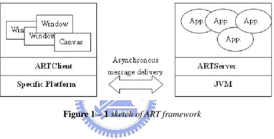
(11) z. We make the GUIs and program logic of mobile applications separate from each other. There are many benefit of this concept. For example, the UI designers and programmers can perform their work independently so that both parts could progress at the same time.. z. On account of the multiplicities of mobile devices’ displayed specifications, the UIs of mobile applications have to be ported repeatedly. We use the technique of code generation [2] and XUL [3] to automatically generate UIs which can adapt to kinds of handheld devices. It can reduce much of the application providers’ effort in writing UIs’ codes repeatedly.. z. Besides UIs, the other parts of a mobile application can be written only once. That implies our mobile applications are protocol and client platform independent; in other words, our framework can accept more than one kind of user environment2. So we can reduce the cost at porting applications to multiple user environments.. z. The framework itself is designed to be modularized very well. When we maintain it or add new functions to it, the effort we spend is as less as possible.. 1.1 ART (Adaptive Remote Terminal) Adaptive Remote Terminal is a client-server model system, and clients communicate with servers by means of an asynchronous message-delivery mechanism. Figure 1-1 (shown in the next page) helps understanding the idea.. Just like X Window System or Microsoft’s Terminal Service, clients of ART can control and operate applications running on remote servers. For example, a programmer can write a. 2. We will use the term “user environment” in this thesis to refer to both hardware and software configurations that users physically contact. 2.
(12) JINI application and run it on a server of ART; then users can control and monitor information appliances from the client of ART.. So, users can send requests to the server by operating GUIs on the client side. Then server of ART will run the application designate by the users’ requests and send the executing results as response back to the client side through network connectivity. The client of ART generates the new GUIs to display the executing results by server’s response.. Figure 1 – 1 sketch of ART framework. 1.2 Motivation This drives us to the question how can we enjoy the benefits provided by ART if there is no usable network on the client side. The handheld devices generally use wireless network3 to access to the internet. But these technologies are not mature nowadays, such as the packets of network bandwidth, the robustness of network QoS (Quality of Service), and the standard of charging. This is the central problem of lacking network connectivity; the mobile applications developed based on the ART framework could not work on the clients’ handheld. 3. It includes Wireless Local Area Network and 3G (Third Generation Mobile Telephony) which is a generic term covering a range of future wireless network technologies. 3.
(13) devices anymore.. There is one further point that we must not ignore. The hardware supported on the handheld devices is becoming much powerful than the past three years. And we can be fairly certain that the executing environments of mobile devices will continuing grow stronger and the resources they have will become plentiful, too.. For reasons mentioned above, it is obvious that we can provide another kind of applications which not only run using the resources provided on the handheld devices but also run at the environment without network support.. 1.3 Objectives. The purpose of this thesis is to find out some ways to increase our ART framework’s capabilities in mobile computing. We will focus on providing a convenient tool for developing mobile applications. The objectives that we want to achieve are as follows: z. A common problem of thin-client computing model is the situation that the network crashes. We will try to make the ART-based mobile applications become disconnected-aware. The disconnected-aware application means that it can still be executed on the resource-constrained mobile devices without network support. There are some researches focusing on this area [4] but not suitable on our ART framework. The researches named “FarGo” in [20] and [21] and “Rover” in [22] are both last for a long time and have great achievements.. z. We wish to transform the mobile applications originally planed to be run on the server side and based on the ART framework into the version which can be run. 4.
(14) independently on the client side. z. When porting a mobile application to the multiple kinds of user environments, we hope to provide some development kits to decrease the porting effort. By the features of the ART framework, there are two parts for developing mobile applications, one is the user interface and the other is the program logic. Both parts will be our objectives to ease the suffering of porting repeatedly. And we can specify the user environments from CC/PP (Composite Capabilities/Preferences Profiles) [17].. 1.4 Organization The rest of this thesis is organized as follows. In the next chapter, we review a few background and related works. The development flows of ART-based mobile applications are provided in Chapter 3. It also announces what components we should provide to attain our objectives. In Chapter 4, we will explain how to implement our architecture in transforming and what rules we stand on during transformation taking place. We list several applications which are useful in our scenarios in Chapter 5. Final chapter is the conclusions and future works.. 5.
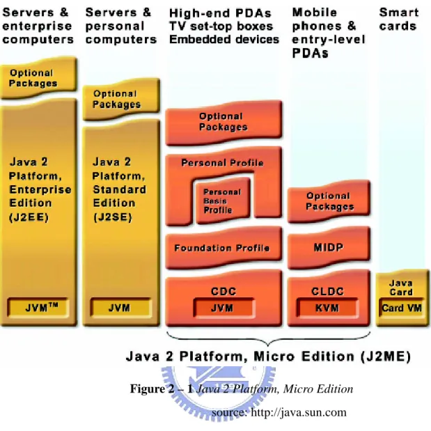
(15) Chapter 2 Background and Related Works 2.1 JavaCC Java Compiler CompilerTM (JavaCCTM) [5] is the most popular parser generator for using with JavaTM applications. A parser generator is a tool that reads a grammar specification and converts it to a Java program that can recognize matches to the grammar. In addition to the parser generator itself, JavaCC provides other standard capabilities related to parser generation such as tree building (via a tool called JJTree included with JavaCC), actions, debugging, etc. We will use this technique to generate a parser for parsing the mobile applications written in Java. By using it, the performance of our development kit will be enhanced.. 2.2 Java 2 Platform, Micro Edition The JavaTM 2 Platform, Micro Edition (J2METM) [6] is the Java platform for consumer and embedded devices and a broad range of embedded devices, such as mobile phones, PDAs (Personal Data Associate), set-top box and smart cards.. The J2ME platform is a set of standard Java APIs defined through the Java Community ProcessSM program by expert groups that include leading device manufacturers, software vendors and service providers.. 6.
(16) Figure 2 – 1 Java 2 Platform, Micro Edition source: http://java.sun.com. There are three parts of the J2ME architecture (indicated by Figure 2-1): configurations, profiles and optional packages. They cooperate to build complete Java runtime environments. Each combination of the three is optimized for the memory, processing power, and I/O capabilities of a related category of devices. The result is a common Java platform that fully leverages each type of device to deliver a rich user experience. The three parts of J2ME are described as follows: z. Configurations provide the base functionality for a particular range of devices that share similar characteristics. They are composed of a minimal set of class libraries based on a virtual machine. There are two J2ME configurations: the Connected Limited Device Configuration (CLDC) [7], and the Connected Device 7.
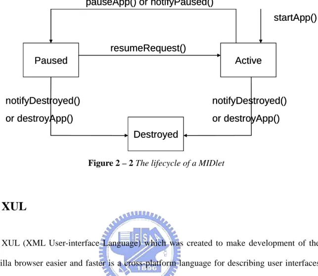
(17) Configuration (CDC). z. Profiles are a set of higher level APIs that CLDC or CDC must be combined with. The collaboration provides a complete runtime environment targeted at specific device categories. The profiles define the application life cycle model, the user interface, and access to device specific properties.. z. In order to address more specific market requirements, the J2ME platform can be further extended by combining various optional packages. Optional packages offer standard APIs for using both existing and emerging technologies such as Bluetooth, Web services, etc.. In the implementation of this thesis the profile we used is the Mobile Information Device Profile (MIDP) [8]. Combined with CLDC, MIDP provides a complete Java runtime environment that for mobile phones and entry-level PDAs. Added to this, MIDP is designed for mobile phones and entry-level PDAs.. 2.3 MIDlet Like applets, MIDlets are managed in an execution environment that is slightly different from that of a Java application. Java applications that run on MIDP devices are known as MIDlets. A MIDlet consists of at least one Java class that must be derived from the MIDP-defined abstract class javax.microedition.midlet.MIDlet. MIDlets run in an execution environment within the Java VM that provides a well-defined lifecycle, represent diagrammatically at figure 2-2, controlled via methods of the MIDlet class that each MIDlet must implement. We will take advantage of these specifications to promote the performance of our development kit.. 8.
(18) pauseApp() or notifyPaused() startApp() resumeRequest() Paused. Active. notifyDestroyed(). notifyDestroyed(). or destroyApp(). or destroyApp() Destroyed Figure 2 – 2 The lifecycle of a MIDlet. 2.4 XUL XUL (XML User-interface Language) which was created to make development of the Mozilla browser easier and faster is a cross-platform language for describing user interfaces of applications. It is an XML-based language, so all features available to XML are also available to XUL. Most applications need to be developed using features of a specific platform, and that makes build cross-platform software time-consuming and costly. In mobile computing environment users may want to use an application on different devices such as handheld devices or set-top boxes.. Because XUL has all the advantages of other XML languages, other XML languages, for examples, MathML or XHTML, can be inserted within it. Moreover, text will be easily localizable; it can be translated into other languages with little effort. Style sheets can be applied to modify the appearance of the user interface (much like the skins or themes feature in WinAmp or some window managers).. 9.
(19) XUL provides most elements that could be found in modern graphical interfaces. They are: z. Input controls such as textboxes and checkboxes. z. Toolbars with buttons or other content. z. Menus on a menu bar or pop up menus. z. Tabbed dialogs. z. Trees for hierarchical or tabular information. z. Keyboard shortcuts. The displayed component can be created from a XUL file or some data source. XUL content may be loaded from a local file or a remote site. In this thesis, we take advantage of XUL to implement our UI model. It will be talked about latter.. 10.
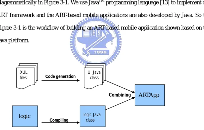
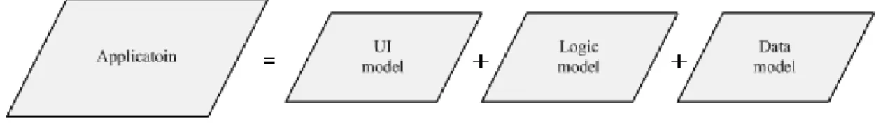
(20) Chapter 3 Programming Framework The development flow of mobile applications based on our ART framework can be separated into two parts; one is designing the XUL file for graphical user interface displayed on the client’s monitor, the other is the program logic for specifying what the program can do. The UI designers and programmers can perform their work independently so that both parts could progress at the same time. Then, we will build the two parts into the applications run on the server side by code generation and compiling. The workflow is represented diagrammatically in Figure 3-1. We use JavaTM programming language [13] to implement our ART framework and the ART-based mobile applications are also developed by Java. So the Figure 3-1 is the workflow of building an ART-based mobile application shown based on the Java platform.. XUL files. Code generation. UI Java class. Combining. logic. Compiling. ARTApp. logic Java class. Figure 3 – 1 Workflow of building an ART-based application. 3.1 Overview There are two aspect we considering for designing the programming framework suitable. 11.
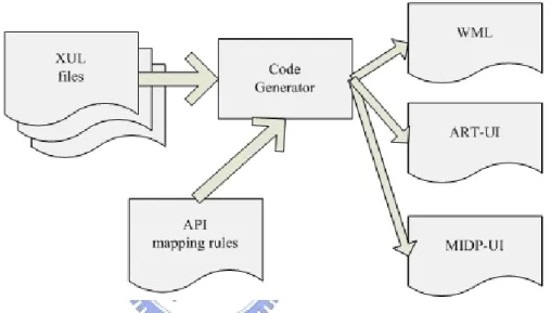
(21) for our new Applications. First, we follow the ART’s original programming framework and separate it into two models, UI and logic. So the new application programming framework is compatible with the original one and we do not need to re-develop the existed ART-based mobile applications. The other aspect is adopting the concept of MVC (Model-View- -Controller) pattern [14]. View is seen as UI model, Controller is similar as logic model and Model is drawn out as the data model standing for the data information we may use during the program’s execution time. We will provide some APIs for the application providers to develop the data model within the mobile applications. In the last few years, several articles have been devoted to the study of using data model in the mobile computing [9].. For reasons mentioned above, the programming model in the newly framework can be divided into three components. These three components are the UI model which presents the user interface’s widgets, Logic model which stands for the executed program logic, and Data model which records the information during the program performed, as sketched at Figure 3-2.. Figure 3 – 2 Our application model. 3.2 UI model Talking about the development in UI model, we still use XUL to describe the displayed component. There are other researches about UI adaption, such as UIML [19] can adjust the. 12.
(22) display styles of mobile applications. It lets UI designers could develop the user interface in the simplest way without considering the multiple kinds of user environments on the client side. There are many researches focusing on the area of UI adaption [18] but still no excellent solutions. So we will adopt the code generator, talked in section 4-2, to map the displayed components from XUL to other platforms which suitable for showing on the user environments. It is represented diagrammatically in Figure 3-1. Figure 3 – 3 UI model transformations. The “API Mapping Rules” in the below left of the Figure 3-3 is a file which records the displayable UIs’ mapping rules from XUL to other programming language. This file is written by an XML-based programming language designed by us after surveying kinds of platforms. We shall introduce it in detain in the section 4.1. Using this mechanism, the code generator can work more generally and also have much decrease in the porting effort.. 3.3 Logic model. 13.
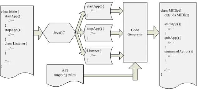
(23) The programming codes in the logic model can be classified into three main groups. First one is the server component, second one is the client component, and the third one is the main logic like the application executing flow. The server component means that it can be executed at the server side and could use the strong computing power and the rich resources. The client component means that it can just be executed at the client side using the runtime environment provided by the handheld devices. Over the last few decades, this topic has been the subject of controversy, such as [10].. We use the JavaTM programming language to be our standard language in developing ART-based mobile applications in our newly programming framework. The reasons why we make this decision are as follows: z. The ART-based mobile applications were written in JavaTM programming language in the original programming framework.. z. Nowadays, there are more and more handheld devices, such as PDA (personal digital assistant), Smartphone, cell phone, WAP phone, Java-enabled handset and so forth, providing the KVM onto their executing environment.. z. Java 2 Micro Edition had provided MIDP (Mobile Information Devices Profile) APIs (Application Programming Interface) for developing mobile applications. We can adopt these APIs to let our developed applications work on the client side.. z. MIDlet is the basic unit in mobile applications using MIDP. It defines three states to present the life cycle of the mobile applications. And the scope of MIDP, application model, user interface, persistent storage, networking and timers, are useful for a mobile application to be executed in the handheld devices.. For the reasons mentioned above, we choose the J2ME platform to be our client sides’ runtime environment. We will get another benefit for making this decision. Since we use J2SE 14.
(24) programming language for developing the server sides’ ART-based mobile applications and J2ME programming language for the client sides’ mobile applications, they are all defined through the Java Community ProcessSM. While transforming the server side’s program into the client side, we do not need to modify the syntaxes. We just need to aim at the API used in the programs and map it to the target platforms.. Same as the UI model, we provide an “API Mapping Rules” file to be the regulations of transformation. The point is that, if we want to port the applications which originally run on the server side to the client side, we just need to transform all the methods invoked by the executing program on the server side into the methods which could be executed on the client side at their running time.. During transformation, if we compare all the statements in the program logical codes to all the API mapping rules, we will not keep performance well. So we try to generate a Java parser which can build a parsing tree and trace out the programming blocks by the program’s architecture. By taking advantage of choosing the programming blocks, the speed of method comparison will be fasten and the performance of API transformation will be promote. Figure 3-4 shows that how we transform the J2SE program into the J2ME program aiming at the programming blocks with the “API Mapping Rules” file.. 15.
(25) Figure 3 – 4 logic model transformations. The “API Mapping Rules” here contains the mappings of J2SE APIs to MIDP APIs, and ART APIs to MIDP APIs. After transformation, if the application has some APIs which can not be executed normally on the client environment, we will show some error messages to tell the application provider. Then the programmer should move the method call into the server side’s component, in order to let the API run using the stronger computing power on the server side.. 3.4 Data model. We abstract the data model from the application programming framework and provide some mechanisms to let it use both on the client side and the server side. Due to the limited memory size on the mobile devices, we cannot store all the data information on the client side. The programmer should write some meta-data to point out which field must be stored on the client side. Therefore the data information can be invoked at local storage.. When developing the applications, the providers can call the data model APIs (defined 16.
(26) by us) which could be used both in the server components and client components. It let the providers have the common interface to use while retrieving the information. We cannot say for certain that we had totally brought up a complete solution in adopting data model on the client side, because we have not provided the synchronous mechanism from client to server. But our design, separating out the data model, let the applications retrieve the data and store on the client’s storage. So users can still retrieve the information on the client side when network crashes. It is convenient and common using for the mobile applications.. 17.
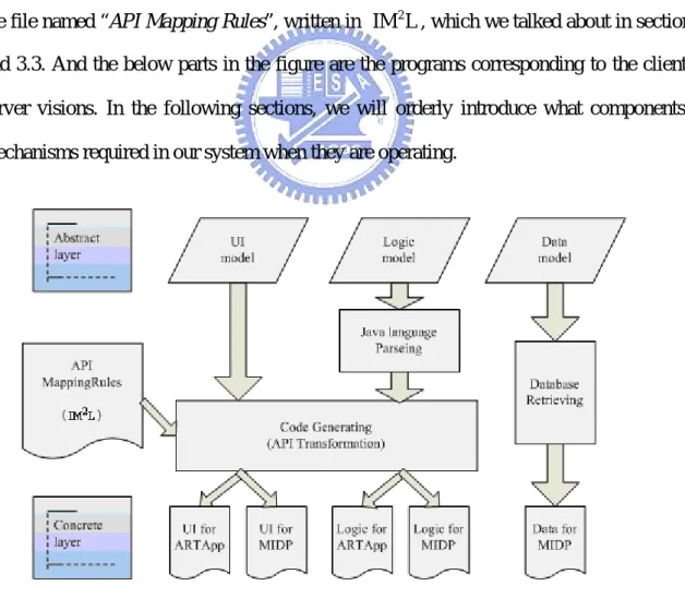
(27) Chapter 4 System Architecture In order to automatically port the server side’s applications to the client side’s mobile applications and decrease the effort spent by the application providers, we design a system to attain our objectives.. The whole system architecture is shown as Figure 4-1. There are the three models classified from the abstract view of the programs at the above of the figure. The middle part is the components we provided for attaining our objectives. The middle left side of the figure is the file named “API Mapping Rules”, written in IM 2 L , which we talked about in section 3.2 and 3.3. And the below parts in the figure are the programs corresponding to the client and server visions. In the following sections, we will orderly introduce what components and mechanisms required in our system when they are operating.. Figure 4 – 1 System architecture. 18.
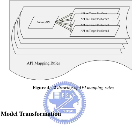
(28) 4.1 Interface Mapping Markup Language ( IM 2 L ) IM 2 L is a XML-based language and its objective is to transform the APIs more generally. We use it to describe the rules about API mappings between different developing platforms. This language is defined by us (ART providers) and we consult the difference between different developing platforms in using the APIs and record the API mapping rules in order to transform the programs through diverse platforms. About the example of using the IM 2 L will be discussed further in section 4.2 and 4.3.. The merits of writing the API mappings through IM 2 L are as the following: z. It matches XML format so it have many available tools that can trace out the rules of mappings.. z. It can be used in both Logic model and UI model.. z. It can record many kinds of API mappings among different developing platforms.. z. It is easy to modify while API revision is occurred. We can directly modify the API mapping rules when there is some change provided by one platform without rewriting a new code generator or altering the old one.. z. It can be expanded easily. When one platform has new APIs, we just need to add the new mapping rules into our recorded file. Then our mapping scope will be expanded.. The file which named “API Mapping Rules”, mentioned in Figure 4-1, is written in IM 2 L , and it is constructed by many of the API mapping rules. Figure 4-2 explains the concept of what the “API Mapping Rules” is. At the Figure 4-2, we can see that there is a source API which can be mapped to other APIs on different target platforms; this whole small 19.
(29) sketch is called an API mapping rules. The “API Mapping Rules” is the biggest graph at this figure, and it contains some API mapping rules in it.. Figure 4 – 2 drawing of API mapping rules. 4.2 UI Model Transformation In order to make User Interface, written by XUL, be shown on different kinds of developing platforms supported on the handheld devices, we use IM 2 L to define the transformations of API mappings.. XUL. ART-UI. MIDP. WML. <window>. Form. Form. <wml>+<card>. <canvas>. Canvas. Canvas. <wml>+<card>+4 direction button+<img src=”…”>. <listbox>. ChoiceGroup. ChoiceGroup. <select>. <button>. Buttom. Buttom. <a href>. <textbox>. TextField. TextField. <input>. Table 4-1. 20.
(30) The capability of IM 2 L in User Interface is to record the API mapping rules of widgets which used in the XUL file and the API mapping rules will describe the usages of APIs on different developing platforms. For example, when we want to add a field of input a bunch of words to the display window on the client side, we have to write in different ways for different developing platforms, as Table 4-1.. In the original design, ART providers have to write different kinds of code generator in accordance with every developing platform. These code generators read the XUL file, and sequentially transform each widget in the file. There are some problems in this design: z. It is not easy to maintain the code generators. The original way is to write the mapping rules in the code generator when there has any necessary transformations between source developing platform and target one. Besides, we have to write a specific generator corresponding to each developing platform. As mentioned above, if we want to modify the statement of transforming the widget, we should trace the programming codes of the code generator and find out the old mapping rules within it for the purpose of substituting the new API for the old one.. z. We have to modify each code generator when a new mapping rule appears. When we provide a new widget for UI designer’s usage, we must modify every generator in each kind of platform in order to update the new way of transforming the widget.. As a result, if we adopt IM 2 L to trace out the mapping rules, we can overcome the two problems mentioned above more flexibly. This set of mapping rules is provided by ART Framework. For program developer on ART, it needn’t take extra effort to understand the content of the document. Figure 4-3 shows a simple example how IM 2 L is used when 21.
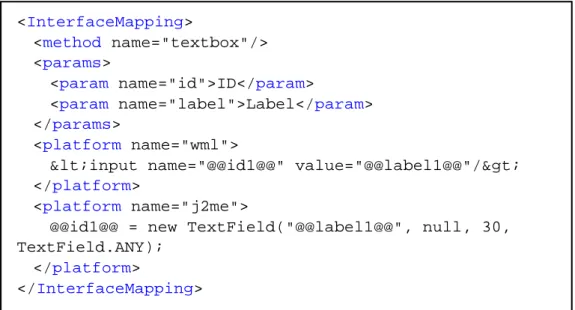
(31) describing the mapping rules between different developing platform targeting at the specific UI widget. The elements used in Figure 4-3 are introduced as the following: z. InterfaceMapping The element defines a set of widgets’ API mapping rules on each platform. The detailed mapping rules are illustrated in this section enclosed by the InterfaceMapping element.. z. method Here, we use method to represent each widget’s name defined in XUL. Our code generator will generate a concrete file of UI model according to the methods used in the XUL files designed by UI designers.. z. params params is an element of a nest shape. It contains lots of argument settings marked by params in its nest shape. It represents the arguments that the widget needs to set itself within the API usage.. z. platform We use this element to record transformation rules about the API usages among different developing platforms. There are two sets of platform elements, we have supported now, in Figure 4-3: wml and j2me. The value in the element is the record about how the API is used at the specific widget and the specific developing platform. We will process the API transformation according to the API usage record in this element.. 22.
(32) <InterfaceMapping> <method name="textbox"/> <params> <param name="id">ID</param> <param name="label">Label</param> </params> <platform name="wml"> <input name="@@id1@@" value="@@label1@@"/> </platform> <platform name="j2me"> @@id1@@ = new TextField("@@label1@@", null, 30, TextField.ANY); </platform> </InterfaceMapping>. Figure 4 – 3 example of mapping rules in UI model. Thus, we know that using IM 2 L to describe API transformations can attain our objectives flexibly. The textbox in Figure 4-3 defines a widget in the XUL. We survey the APIs used for displaying the widget on different developing platforms, and record them in the element value of platforms. By setting some required parameters in the APIs, we can get the complete usage of APIs on all sorts of developing platforms. Then we can port the programming codes to different developing platform without any effort.. 4.3 Logic Model Transformation The architecture of implementing the transformation in logic model is shown as Figure 4-4; it includes two components developing by JavaCC and JDOM [11], which both are the available techniques written in Java. These two components will read the original programming codes, indicates “Program logical codes (server)” at the top left of the figure, run on the ART server and the API mapping rules, indicates “API mapping rules” at the top right, written in IM 2 L ; after read these two files, “Code Generator”, marked in the middle, will use the “Transformer” to compare the statements with the mapping rules and to transform. 23.
(33) the matched statements into the target statements. Finally, we will get the “Program logical codes (client)” which composed by the target statements and it can be executed on the client side.. Figure 4 – 4 architecture of code generator in logic model. The two available techniques, JavaCC and JDOM, we used in the logic model shall be examining how we exploited them to fulfill our requirement in the continuing paragraph.. We use JavaCC to generate a Java parser which can help us checking the programming blocks and the APIs’ name using in the applications. The Java parser contains many Java language grammars written in regular expressions. We can make use of it to build a parsing tree and note down the interested information into a temporary file. Such as the statements in the programming block and the APIs’ name and parameters used in the original application programming codes are inscribed in the temporary file. Then, the main component doing the compared and transformed task can easily get the marshaled information and have the better performance.. 24.
(34) JDOM is a new API which can let programmers handle the XML documents as Java objects. It also improves the performance in accordance with Java. So, JDOM can handle a XML document as we with just like DOM and have the well performance as SAX. We use JDOM to trace out the mapping rules recorded in the API mapping rules written in IM 2 L . By using the mapping rules, we can find the corresponding APIs within the target developing platform and forward the information to the Code Generator which is responsible to the comparison.. IM 2 L in the aspect of using in logic model is mainly in describing how the APIs, which is run in the application on the ART server, should be transformed into the APIs which can be run upon the runtime environments on the client side. As we mentioned in the section 3.3, the mobile applications run on the client side and the server side are both written in Java, so we do not need to modify the syntaxes and the semantics of the statements during transformations. What we should do to port the program logical codes into different platforms is tracing out the APIs among the statements and transforming these to the target platforms according to the mapping rules written in IM 2 L . Figure 4-5 is an example for describing the API mapping rules written in IM 2 L using in the logic model. The explanations of what the elements do are as follows: z. InterfaceMapping The element defines a set of API mapping rules within various developing platforms. The detailed mapping rules are illustrated in this section enclosed by the InterfaceMapping element.. z. class It records what class the API belongs to. In the Object-Oriented programming language, it is a common usage to specify the references of the APIs.. z. method 25.
(35) The value of this element specifies the method’s name of the API. We will use the value of method and params, which will be talked later, to construct the mapping rules. z. progBlock progBlock is abbreviate from the programming block. The value of this element can be “startApp”, “stopApp”, “listener” and “all” which is the default value. The functionality of using it is to promote the performance of the API transformations. The reason is that some APIs can just be used in some programming block or just be called during the life state of the applications in MIDP, so we do not have to compare these APIs in other programming blocks. This mechanism of adopting this element can make the performance well.. z. params params is an element of a nest shape. It can have lots of argument settings marked by parameters within. And it represents the argument that the API needs to set in itself.. z. platform This element is used in recording the API transformation rules corresponding to different developing platforms. There are two sets of platform elements in Figure 4-5 and it means that we support the API transformations between these two developing platforms. The first one in the name attribute of the platform is j2se and it records the usage of the specified API run on the j2se platform in its element value. Second is j2me and it also records the usage of the corresponding API in the j2me developing platform. By adding element of platform directly, we can easily extend our API transformations to a new developing platform, such as PJava [15].. 26.
(36) <InterfaceMapping> <class>com.art.ui.Form</class> <method>show</method> <progBlock/> <params /> <platform name="j2se"> @@obj1@@.show(); </platform> <platform name="j2me"> Display.getDisplay(this).setCurrent(@@obj1@@); </platform> </InterfaceMapping>. Figure 4 – 5 example of mapping rules in logic model. In the transformation of logical programming codes, we had defined the mapping rules from the APIs provided in ART to the APIs provided in MIDP completely. The mapping rule shown in Figure 4-5 describes the API usage of displaying a window on the ART platform can be transformed to the API of setting a window to the displayable object in the MIDP. Because we can only display a window on the monitor of handheld devices, we should select a suitable API to attain the same purpose on the client side. Here, we choose the API named setCurrent in MIDP and pick up a Displayable object as the parameter. In other mapping rules, we can also ensure that they will work well after transformed to the APIs run on the client side.. 4.4 Data Model Design. In the implementation of data model, we provide two aspects of development tools. First, we provide some database API which can be used during application programming period both suitable on the server side and client side. Secondly, we define the data model schema used to specify what fields are the necessary data and should be provided on the client side during application executed. We shall now look more carefully into our consideration of the 27.
(37) design issue in data model.. 4.4.1 Database API. A J2SE application typically stores state in local files that are easily and quickly accessible from the hard driver or transparently accessible over a fast local area network. The Mobile Information Device Profile provides a mechanism for MIDlets to persistently store data and later retrieve it. This persistent storage mechanism is modeled after a simple record oriented database and is called the “RMS” which is the abbreviation of “Record Management System”. These two runtime environments present the difference of using APIs between server side and client side. So on the server side, J2SE provides an API package named java.sql for accessing and processing data stored in a data source (usually a relational database) using the JavaTM programming language. On the client side, the Mobile Information Device Profile provides an API package named javax.microedition.rms for MIDlets to persistently store data and later retrieve it.. In our way of solving different APIs between the server side and client side in the logic model and UI model mentioned above, we designed an IM 2 L to note down the mapping rules corresponding to different developing platforms. But because of the congenital usage of database APIs between J2SE and MIDP, the mechanism we adopted previously cannot work very well in the data model. So we try to design some APIs followed the javax.microedition.rms provided on MIDP as a model, shown as Table 4-2:. boolean. addRecord (byte[] data). boolean. closeDB (). 28.
(38) boolean. connectDB (String driver, String url, String dbname, String passwd). boolean. deleteRecord (int recordID). int. getRecordID (Object primaryKey). byte[]. queryRecords (Object primaryKey). boolean. recordExist (Object primaryKey) Table 4-2. We provide the common interface for the programmers to retrieve information both in the server-side and client-side applications. In the bottom layer, we still use the APIs supplied by the Java Community ProcessSM respectively to implement our database APIs. We have adequate reasons of thinking that providing a common interface is a good way in the performance of transforming applications between various developing platforms because the job of transforming APIs is needless. In addition to this, the APIs are very simple and also convenient for the application providers to use.. 4.4.2 Data Model Schema. We devise a data model schema of specifying which column of data should be shifted to the client side. So we ask the application providers to write a data model file which should follow our schema. Figure 4-6 is an example for describing the details of the columns using in the data model. The explanations of what the elements do are as follows:. 29.
(39) <artdb> <dbschema> <table name="AddressBook"> <primarykey>Name </primarykey> <field name="Name" type="String" description="" /> <field name="Gender" type="String" description="" /> </table> </dbschema> <toRMS> <table ref="AddressBook"> <field ref="Name" /> </table> </toRMS> </artdb> Figure 4 – 6 example of building a data model. z. artdb The element is the root of our data model. We will use the information inside to specify which column is essential and should be shifted into the storage on the client side.. z. dbschema This element can demonstrate how many tables are used in this data model. We can take advantage of the element’s value to build a database using Structured Query Language (SQL) [16].. z. table It manifests the table’s information inside. There is no standard database schema in W3C and still many groups devoted themselves to define a welcome schema. In order to simplify our data model, we define our database schema and take down below the table element. It can be changed into the standard one easily afterwards.. 30.
(40) z. primarykey We use this element to assign which field is the primary key of this table.. z. field This element is used to clearly show the columns in the table. The “name” and “type” attributes are defined as #REQUIRED, so we cannot miss it. The attributes we defined to describe the field are not very completely corresponding to the relational database nowadays. For example, data length, allow nulls, default value, precision, scale and so forth, are the additional attributes provided by Microsoft SQL server. We simplify the designation and trace out the attributes which is necessary for building up the data model on both client and server side.. z. toRMS The element specifies which field is essential and should be transferred to the Record Management System on the client side. We use the type of “IDREF” at the elements’ attribute to trace out the definition of the element. The functionality of this element can be schematized as figure 4-7. The bottom left of the figure 4-7 indicated “with all columns” is on the behalf of the server side’s data model objects; it contains all the columns regardless whether the field is essential. And the bottom right of this figure is the data model object specialized for client side storage; it only contains the essential fields which marked in this toRMS element in the data model XML file.. 31.
(41) Figure 4 – 7 code generator for data model. In one of our future work is to provide a graphical user interface tool such as IDE (Integrated Development Environment) to ease the development of ART-based mobile applications. By using our IDE, the application providers do not need to learn how to follow our schema and write the data model files; he (she) can just fill up some text fields to finish the data model design. Then the development effort will be decreased.. 32.
(42) Chapter 5 Implementation After introducing our programming framework and how we design the system architecture to attain our objectives, we will go into details to our implementations. This chapter could be partitioned into two parts. The first part includes details of several mechanisms that we transform an ART-based application into a mobile application of MIDP. The second will show some applications which are suitable for the new capabilities we provide in the ART framework.. 5.1 Mechanisms. 5.1.1 Writing an ARTApp ARTApp is the application which written to be run on the ART server, and we need to execute the application through network support. The ARTApp can provide gorgeous capabilities by using the stronger power and rich resource on the server side. The full programming procedure and sample example are shown in the reference at [1]; the following is the brief procedure which can be split into several steps: 1. State initial UI in XUL and save them. 2. Create a new Java file by the name of Main.java, and there must be a class named Main in it. 3. The class Main has to extend from class ARTApp. 4. Developers must implement two method in class Main, startApp and stopApp. And in the beginning of startApp, developers have to set the ARTApps to. 33.
(43) SINGLE or MULTIPLE modes. 5. Before a window is used, its static method getInstance needs to be invoked first. The return value is a reference of that window. Every widget declared in XUL documents can be used immediately. 6. If the status of a widget needs to be monitored, developers have to create and set a listener for this widget. Listeners will notify ARTServer if events of widgets happen. But simple and complete ARTClient cannot suit the same listener; for example, number key events are able to be detected by MIDP version but not by WAP version of ARTClient. 7. Developers can write the program logic now. 8. When developers build the Main.java, the code generator that will be discussed in next section transfers XUL files into Java source files first. Then java compiler (javac) will be able to compile them (UI source files and Main.java). Finally, we will get the ART-based mobile application run on the ART servers.. In the procedures, we will see that the mobile application developers just need to specify some widgets in UI model. The remains of the program are program logic, and developers do not need to maintain network status themselves. Thus the programming of mobile applications with ART is very easy.. When developing a mobile application run with database, there is something additional need to set up. On the one hand the developers should build a file system or database system, and on the other hand they need to write a XML file to indicate the data model supported in this mobile application.. 34.
(44) 5.1.2 Code Generator. The code generator that works within our mechanisms in the logic model and UI model transforms specified source files into target files by checking the API mapping rules written in IM 2 L . The GUI and program logic of a mobile application (ARTApp) can be developed simultaneously by different people. And we will generate the codes separately. z. Code generator in UI model Figure 5-1 is a collaboration diagram indicates that what components we had. implemented to do the work of transforming APIs in UI model into the target source files. Because the user interfaces are designed in XUL, which is a XML-based language, so we can adopt the available tools from XML to implement our “XULParser”, which is at the top left of this figure. The main object is called “ARTCodeGen”, at the middle of the figure, and it is responsible for generating the UI codes fit the target developing platforms. Before the transformation, “ARTCodeGen” will first get the XULData from “XULParser”, and get the mapping rule from “IMMLFilter” secondly. “IMMLFilter”, at the top right of the figure, can filter out the mapping rules by our specified target developing platform. After preprocessing, “ARTCodeGen” will call the compareAPI method provided by “Transformer”, at the bottom of this figure, to check whether the XULData can be mapped to the target developing platform or not. If the return value is true, we can transform it with ease; otherwise, we will show some error messages to indicate the application provider that there is something wrong during the transformations.. 35.
(45) Figure 5 – 1 collaboration diagram for code generator in UI model. z. Code generator in logic model Besides the UI model transformation, we use the similar way to transform the APIs. in the logic model. The only difference between these two models is the component we used to read the source files. At the top left of the figure 5-2, it is “JavaParser” instead of “XULParser” responsible to read the statements of program logical codes. For the explanation of using the “JavaParser”, we must point to the different developing language using in the source files. We noted a little earlier that we choose the Java programming language to develop the server-side and client-side applications. In the section 3-3 and 3-4, we pointed out that the Java programming source file will first be separated into programming block for better performance. Hence the “JavaParser” is implemented by the JavaCC technique and can adequately finish the segmented works. The follow-up operations are the same with UI model transformation mentioned at the second paragraph from this section. To enumerate the flow of transformation repeatedly would only be tedious for the reader, so I shall waste no words on it.. 36.
(46) Figure 5 – 2 collaboration diagram for code generator in logic model. z. Code generator in data model Because the data objects used on the server and client sides are not the same, we. provide a “DBObjectGen” to solve this problem. At the top of figure 5-3 is the “DMFilter” object; it reads the file of data model and parses out the data structure of the records. By setting the argument of the method named codeGenerate, which is the boolean type for specifying if it is a client component or not. When we want to get the “ServerDataObject”, we will set the parameter into false and the “DBObjectGen” will generate the data object with all fields specified in the data model. Relatively, the “ClientDataObject” is the necessary fields we will use on the client side and we can depend on the “DBObjectGen” to generate with the parameter setting to true. We had explained it clearly in the section 4.4.2.. 37.
(47) Figure 5 – 3 collaboration diagram for code generator in data model. 5.1.3 Store Records. In the implementation of storing records on the client side, we consult many investigations on the runtime environment provided for handheld devices. Though a great deal of effort has been made on storing records on handheld devices, the results of investigation lack for a general solution. In order to provide a widely resolution of storing records on the client side, we use the file system which can be supported by all the executable mobile devices for a relay.. Here is a figure which shows the sequence diagram of how we attained our objectives on the MIDP virtual machine. We implement two classes for packing the data information to client side. The first one is the “DBDelegate” class, working at server side, responsible for data retrieving and writing the records to a file. Then, we will package the file and download it with ARTApp to the client runtime environment. When a MIDlet is at its first running, we use the other class we implemented, “ShiftToRMS”, to retrieve the records in the file and store them in the RMS provided by MIDP.. 38.
(48) Figure 5 – 4 sequence diagram for running with data model. 5.2 Applications Here, we propose two kinds of usages of ART applications which can be run independently on the client side; they are listed as follows: 1.. single player in the multi-player game We had provided an application usage of ART which can let users collaboratively. work with the same application on the ART server. One fascinating application is to provide a game service on the ART server and then the users can act as a player entertaining in the multi-player game on the handheld devices.. 39.
(49) By adopting our transforming functionality, when someone wants to play it alone, he does not need to connect to the ART server through network connectivity. It will provide great user experience and costless of the network connectivity’s fee. The most powerful functionality is that the application providers do not need to re-write the game logic for the handheld devices. In our development tools, we can automatically transform the original ARTApp into a MIDP application without additional effort.. In the left of the figure 5-5 is a selecting window in a multi-player game, named “pushpuzzle” runs on the MIDP emulator; the player can choose which one of the game he wants to join in. And every player must connect to the servers via network connectivity support in order to collaboratively control this multi-player game. The right part of the figure 5-5 is the same application, produced through our transforming tools, which can be executed as a mobile application on the handheld devices independently without porting repeatedly to different developing platforms.. Figure 5 – 5 pushpuzzle. 2.. data retrieving in the local storage 40.
(50) The enormous data storage system on the server side can record multiple kind of information which might be necessary or unnecessary. And we can connect to the persistent data storing services on the server side and operate the information such as inserting, deleting and querying through network support. But there exists a problem, discussed several times in this thesis, is the incapable network support. We cannot access the persistent data storing services without network connectivity.. By adopting our transforming functionality, the information which is necessarily during application executed can be encapsulated into the client side. So we do not need to worry about the operations of query the data will be failed or delayed through the non-robust network environments.. In the left of the figure 5-6 is a resulting window after a query operation on the server side. The data we retrieved are not only the necessarily information, name and email, but also the middle-necessarily or unnecessarily information, age and birth. But when we are in the situations that we must query the data locally on the client side, we can also get the necessarily information to use in no time. The reason why we can just provide the necessarily information is that the handheld devices are always limited-storage against the server level computers.. 41.
(51) Figure 5 – 6 querying address book. These two kinds of mobile application have the same benefit of need no network support while executed. We provide a non-porting mechanism to let the ARTApp become disconnected-aware and can be executed independently on the handheld devices. There is no restriction that a disconnected-aware ARTApp must be only one of these two types of applications.. 42.
(52) Chapter 6 Conclusion and Future Works 6.1 Conclusion So far, we have described the merit of providing mobile applications based on our ART framework. The mobile applications can be executed with rich resources and strong computing power on the server side and displayed the executing results by drawing widgets within a window through the network connectivity via the handheld devices on the client side. But, this powerful adaptive mobile application development framework has some defects that the applications could not work normally in the environment of no network connectivity support.. This paper provides a development kit which can automatically transform the ART-based mobile applications to the applications that can be run on the client side independently. By using these transforming tools we can achieve the objectives mentioned in Chapter 1 and redeem the drawbacks in the original system architecture. The main advantages of using our development kit are as follows: z. Easily providing disconnected-aware mobile applications.. z. Automatically transforming the application from the server version to client version.. z. Reducing the porting effort while transforming applications to match the client side runtime environment.. We attain these objectives by designing a XML-based language named IM 2 L which is. 43.
(53) detailed expression through section 4.1 to 4.3. By reading the files written in IM 2 L and the program logical codes in the original application which is run on the server side, we can achieve the goal of porting the applications to the ones which can be run on the client side. It can not only using the resources provided on the local side within the handheld devices as well but substantially decreasing the repeatedly porting effort about program logical codes and user interface codes on the client side by the application providers.. It should be concluded, from what has been said above, that ART, a mobile application development framework, nowadays can support the mobile applications to be run using the rich resources and the stronger computing power on the server side through network support. And one other thing that is important for mobile applications is the local computation using the resources provided on the client side. These full-scale of capabilities provided by the ART framework could be applied in enormously aspects.. In order to ease the suffering of mobile application development on the ART framework, there are still several points can be enhanced into our development kit. We place them in the next section and wish that we could make our development kit more completely.. 6.2 Future Works There are several different directions to explore in future development of our development kit. We now provide the API transformation based on the JavaTM programming language at first. But there is not just one developing platform supported on the handheld devices. We wish that the target platform of transformation could be supported more widely and the developing works can be more easily, so we propose a few future works that enhance our development kit. 44.
(54) z. Complete the API mapping rules The IM 2 L we defined can be used in multiple aspect, such as logic model and UI. model, and it can support multiple developing platforms in using APIs. As we extend the API mapping rules from one developing platform to a new one, we can easily achieve the goal of porting the original application to a new developing platform. The transformations between developing platforms have recently brought to light by the vendors of programming languages. “JUMP to .NET” Strategy [12] is one of the transformations that automatically convert existing Java-language source code into the C# programming language. But it is just a beta version. z. Develop the Graphical Integrated Development Environment Integrated Development Environment (IDE) is the most convenient development kit. to application providers. So in our continuing research, we wish to provide a graphical IDE tools in the development of user interface and the designing of data model in order to let the ART-based mobile applications be developed more facile. There is much truth in this that it will make the progress of mobile computing enormously.. 45.
(55) Reference. [1] 姚立三, 袁賢銘, ”An Adaptive Mobile Application Development Framework”, 國立交 通大學電資學院學程碩士班論文,民國 92 年 6 月 [2] 楊淑芬, ”Code Generator for XML-based Universal Service Terminal Framework”,國立 交通大學,碩士, 民國 91 年 6 月 [3] XML User Interface Language (XUL), http://www.xulplanet.com/tutorials/xultu/ [4] Weinsberg, Y., Ben-Shaul, I., “A Programming Model and System Support for Disconnected-Aware Applications on Resource-Constrained Devices”, Software Engineering, 2002. ICSE 2002, Proceedings of the 24rd International Conference on, 19-25, May, 2002 [5] java.net, The Source for JavaTM Technology Collaboration, JavaCC Project, https://javacc.dev.java.net/ [6] Sun Microsystems, “Java 2 Platform, Micro Edition (J2ME)”, http://java.sun.com/j2me/ [7] Sun Microsystems, “CLDC”, http://java.sun.com/products/cldc/ [8] Sun Microsystems, “Mobile Information Device Profile (MIDP)”, http://java.sun.com/products/cldc/ [9] Marques, P.J.; Silva, L.M.; Silva, J.G., “A Flexible Mobile-Agent Framework for Accessing Information System in Disconnected Computing Environment”, Database and Expert Systems Applications, 2000. Proceedings. 11th International Workshop on , 4-8 Sept. 2000 [10] JIN JING, ABDELSALAM (SUMI) HELAL, AHMED ELMAGARMID, “Client-Server 46.
(56) Computing in Mobile Environment”, ACM Computing Surveys, Vol. 31, No. 2, June 1999 [11] JDOMTM Project, http://www.jdom.org/ [12] Java User Migration Path to Microsoft .NET http://msdn.microsoft.com/vjsharp/jump/default.aspx [13] Sun Microsystems, “Java 2 Platform Technologies”, http://java.sun.com/ [14] Leff, A.; Rayfield, J.T.; Enterprise Distributed Object Computing Conference, 2001. EDOC '01. Proceedings. Fifth IEEE International , 4-7 Sept. 2001, Pages:118 - 127 [15] Softwired Inc., iBus, http://www.softwired-inc.com [16] SQL (Structured Query Language) Tutorial, http://www.w3schools.com/sql/default.asp [17] W3C, “Composite Capability/Preference Profiles (CC/PP): A user side framework for content negotiation”. http://www.w3.org/TR/NOTE-CCPP/ [18] 3GPP project, Universal Mobile Telecommunication System (UMTS) standard, http://www.umts-forum.org/ [19] User Interface Markup Language (UIML), http://www.uiml.org/index.php [20] Holder, O.; Ben-Shaul, I.; Gazit, H.; “Dynamic layout of distributed applications in FarGo” Software Engineering, 1999. Proceedings of the 1999 International Conference on , 16-22 May 1999 Pages:163 – 173 [21] Holder, O.; Ben-Shaul; “FarGo”, http://www.dsg.technion.ac.il/fargo/ [22] Frans K.; David G.; Anthony J.; George M.; Joshua A.; “Rover”, http://www.pdos.lcs.mit.edu/rover/. 47.
(57)
數據
+7
相關文件
• Instead, static nested classes do not have access to other instance members of the enclosing class. • We use nested classes when it
• Non-static nested classes, aka inner classes, have access to other members of the enclosing class, even if they are declared private. • Instead, static nested classes do not
Gershman, "Leveraging Behavioral Patterns of Mobile Applications for Personalized Spoken Language Understanding," in Proc.. ▪ Task: user
Windows/ Linux/ Mac 各種平台的開發套件,使我們能夠透過各種平台來開發 Android 軟體,所有的 Android 應用程式都是使用 Java
Keywords : Mobile Digital Devices, Supply Chain, Technology Acceptance Model, Regression Analysis, Sales Force Automation
Excel VBA 乃是以 Visual Basic 程式語言為基礎,提供在 Excel 環境中進 行應用程式開發的能力。在 Excel 環境中「Visual Basic 編輯器」提供了一個
本研究以河川生態工法為案例探討對象,應用自行開發設計之網
本研究以河川生態工法為案例探討對象,應用自行開發設計之網
