Abstract
The finite element analysis and experimental approach were employed to examine the flow-through phenomenon occurred in the press forging of AZ31 magnesium-alloy sheets. The material properties tests suggest that the press forging of AZ31 sheets is required to be performed at temperatures higher than 300◦C. An optimum element size was determined first to simulate the appearance of flow-through and the finite element analysis reveals that the formation of flow-through is mainly due to the insufficient material in the neighborhood of the embossment. The finite element simulation results also indicate that the sheet thickness and the dimension of the embossment are the major factors affecting the occurrence of flow-through. Based on the sheet thickness and the embossment dimensions, the limiting curves for the occurrence of flow-through were established in the present study to predict if the flow-through would occur. These curves provide an important guideline for the press forging design. © 2007 Elsevier B.V. All rights reserved.
Keywords: Press forging; Flow-through; AZ31 magnesium-alloy sheet; Embossment
1. Introduction
Magnesium-alloy has attracted much attention from the elec-tronics industry in the applications of thin-walled structural components, such as the casings of notebook, mobile phone, and digital camera, due to its superior properties of light-weight, high specific strength, and good resistance to the electromagnetic interference (EMI). Most of the thin-walled structural compo-nents used in the electronics industry possess a geometric shape with embossments, as shown in Fig. 1(a). The principal fab-rication process of the magnesium-alloy components has been die casting. However, the press forging process, which has con-siderable potential because of its competitive productivity and performance, recently emerges as an alternative process in the manufacture of thin-walled magnesium-alloy electronics com-ponents. Different from the traditional forging processes using bulk material as blanks, the press forging process squeezes a thick sheet in the thickness direction to provide enough material to form the embossments. However, magnesium-alloy normally exhibits limited ductility at the room temperature due to its hexagonal close-packed (hcp) structure and requires thermal activation to increase its ductility and formability. As for press
∗Corresponding author. Tel.: +886 2 23661322; fax: +886 2 23631755.
E-mail address:fkchen@ntu.edu.tw(F.-K. Chen).
forging, the AZ31 (aluminum 3%, zinc 1%) sheet is consid-ered as the suitable magnesium-alloy for the forging process at the present time due to its better formability compared to other magnesium-alloys [1,2], though considerable efforts are being continuously devoted by metallurgists to developing new wrought magnesium-alloys.
Under certain forming conditions, the formation of an embossment in a press forging process will result in a cavity, which is termed “flow-through” in the present study, on the reverse side of the embossment, as shown inFig. 1(b). The flow-through is considered as a critical defect of the product since the reverse side of embossment is usually a surface of appearance in the product. Although a lot of efforts have been made on the press forming of magnesium-alloy sheets, most of them are focused on the stamping process[3,4], and few of them are with respect to press forging, not to mention the discussions on flow-through. In the present study, the deformation mechanism of flow-through and the effects of process parameters on the formation of flow-though were examined using both the finite element analysis and the experimental approaches. Since the press forging processes of magnesium-alloy sheets are performed at elevated tempera-tures, the mechanical properties of AZ31 were first examined at various temperatures. The ring compression tests were also conducted to obtain the friction factors (m) at the die–workpiece interface at various temperatures with different lubricants. The effects of process parameters on the formation of embossments 0924-0136/$ – see front matter © 2007 Elsevier B.V. All rights reserved.
Fig. 1. Embossment and flow-through in an electronics product. (a) Emboss-ment; (b) flow-through.
were then studied with the finite element simulations performed in a systematic approach. The limit curves for the press forging of thin-walled magnesium-alloy components without the occur-rence of flow-through were also established from the finite ele-ment simulation results. In addition, experiele-ments of press forg-ing process were conducted to validate the finite element analy-sis. The good agreement between the experimental data and the finite element results confirms the validity of the finite element analysis and the design guideline established in the present study.
2. Mechanical properties and friction factors at elevated temperatures
The compression tests were performed at 25, 100, 200, 300, and 400◦C, under various strain-rates of 0.05, 0.5, and 5 s−1, respectively, to obtain the stress–strain relations of AZ31 magnesium-alloy. In order to retain the constant temperature and the constant strain-rate during the compression test, the Gleeble 2000 testing machine was used to conduct the compression tests. Fig. 2shows the stress–strain relations of AZ31 magnesium-alloy at various testing temperatures under the strain-rate of 0.5 s−1. It is clearly seen in Fig. 2that the AZ31 magnesium-alloy can barely sustain very little deformation at temperatures under 100◦C and the deformation increases significantly at temperatures above 200◦C. The flow stresses also drop as the temperature increases, as shown inFig. 2. However, as seen in Fig. 2, the gap between the stress–strain curves becomes smaller as the temperature raises from 300 to 400◦C. It suggests that 300◦C could be an effective forming temperature for the press forging of AZ31 magnesium-alloy.
In bulk forming processes, such as press forging, a friction factor m is usually applied to calculate the friction shear stress f
Fig. 2. Stress–strain relations of AZ31 sheets at various temperatures (˙ε = 0.5 s−1).
according to the formula f = mk, where k is the shear yield stress of the deforming material and 0≤ m ≤ 1. The ring compression tests[5]were performed at 200, 300, and 400◦C, respectively, to evaluate three friction conditions at the die–workpiece inter-face: tests with lubricants MoS2or graphite at the die–workpiece interface, and without lubricant. The testing results reveal that the effect of testing temperature on the friction factor is insignificant, and the values of m are 0.2, 0.4, and 0.7 for lubrication with MoS2, graphite, and without lubricant, respectively.
3. Finite element models
Both 2-D and 3-D finite element analyses were preformed in the present study to investigate the deformation mechanism of flow-through and the effects of process parameters on its forma-tion, using the software DEFORM. In the 2-D finite element analysis, an axisymmetric model was adopted. On the other hand, a square-shaped model was constructed for the 3-D finite element analysis. Both punch and die were treated as rigid bodies and the sheet-blank was meshed using the 4-node axisymmetric element and 4-node tetrahedral element for 2-D and 3-D analy-ses, respectively. The material properties and the friction factors at various temperatures obtained from the previous experiments were adopted in the finite element simulations.
Since the dimension of flow-through is usually rather small compared to other dimensions in the finite element model, the element size of the blank in the neighborhood of the emboss-ment needs to be refined enough to simulate the formation of flow-through. The flow-through phenomenon cannot even be detected if the element size is too large compared to the dimen-sion of embossment. Convergence tests have been performed in both 2-D and 3-D finite element analyses to determine the suitable element size of the blank around the embossment. The convergence test results reveal that the element size of one-tenth of the embossment radius is an optimum value for both 2-D and 3-D finite element analyses.
4. Effects of process parameters on the formation of flow-through
In order to study the effects of the process parameters on the formation of flow-through, the material flow in the press forging
it can be inferred that the formation of flow-through is related to blank thickness, blank size, the dimension of embossment, and the width of side-wall, in addition to the forming tempera-ture and friction condition. The finite element analysis was then performed to investigate the effect of those process parameters on the formation of flow-through. In each simulation, the height of embossment (Hf) at the incipient of the formation of flow-through is used as an index for comparison. The larger value of Hf means the less opportunity to initiate flow-through. The values of Hf in the press forging processes with various blank dimensions at forming temperatures of 200, 300, and 400◦C, respectively, were investigated first. The simulation results indi-cate that the forming temperature has an insignificant effect on the formation of flow-through. It is also noticed from the sim-ulation results that the value of Hf becomes larger as the blank size increases. It implies that the larger the blank size, the less is the tendency of the formation of flow-through, because the larger blank has sufficient material to form both embossment and side-wall.
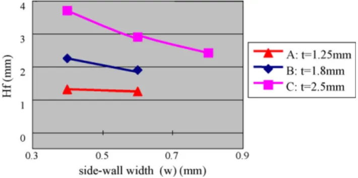
The effects of blank thickness (t) and side-wall width (w) on the formation of flow-through are indicated inFig. 3. Since a thicker blank has enough material under the embossment, it is easy to avoid the initiation of flow-through. Hence, as seen in Fig. 3, the blank thickness has a significant effect on the forma-tion of flow-through. It is also noted inFig. 3that for thinner blanks, the flow-through is easy to initiate and the effect of side-wall width is insignificant. The dimension of the embossment also has a significant effect on the formation of flow-through. The simulation results show that the value of Hf decreases as the dimension of the embossment increases, demonstrating that the larger the embossment, the easier is the formation of flow-through. This trend is attributed to the large amount material required to flow into the embossment, causing the initiation of flow-through.
Fig. 3. The influence of blank thickness and side-wall width on flow-through.
Fig. 4. The influence of shear friction factor (m) on flow-through.
The effect of friction on the formation of flow-through was also examined using the finite element simulations. The friction factors at the punch–blank interface and the die–blank interface were denoted by m1 and m2, respectively, and various values of 0.2, 0.4, and 0.7 were assigned to both m1 and m2 for the simulations with the other process parameters remaining the same. The simulation results were depicted in Fig. 4with Hf value as the ordinate and blank dimension as the abscissa.
The curves B and C shown inFig. 4indicate when both the punch–blank interface and the die–blank interface have the same value of friction factor, the larger value of friction factor is in favor of avoiding the occurrence of flow-through. The further investigation reveals that the friction at the die–blank interface (m2) has more significant effect on preventing the initiation of flow-through compared with the friction at the punch–blank interface (m1), as shown by the pairs of curves B and A-D. It implies that the die–blank interface has more significant effect on the material flow in the formation of embossment and flow-through.
5. Limit curves for the occurrence of flow-through
It is concluded from the previous investigation that the major parameters affecting the formation of flow-through are the blank thickness and the embossment dimensions. For most electronics products, the radii of embossments are ranged from 1 to 3 mm, and the heights of embossments are usually less than 6 mm. In order to predict whether the flow-through will occur or not in the press forging process, a criterion was established using the height and radius of an embossment and the blank thickness as parameters. The finite element simulations were performed to determine the limit values of embossment radius and blank thickness, which cause the onset of flow-through, for a fixed embossment height with other process parameters remaining the same. The simulation results for the embossment height of 4 mm are displayed inFig. 5in which both the conditions with and without the occurrence of flow-through are plotted. The curve enveloping the points, which represent the conditions with flow-through, is defined as the limit curve for the occurrence of flow-through. It means that if the designed values of embossment radius and blank thickness for the embossment height of 4mm are below this limit curve, the flow-through is apt to occur in the press forging process, and a special process design is required
Fig. 5. The limit curve for the occurrence of flow-through with embossment height of 4 mm.
to avoid the occurrence of flow-through. Similar limit curves were also constructed for the embossment heights of 5, and 6 mm, respectively, in the present study. These curves provide an important guideline for the press forging design.
6. Experimental validation
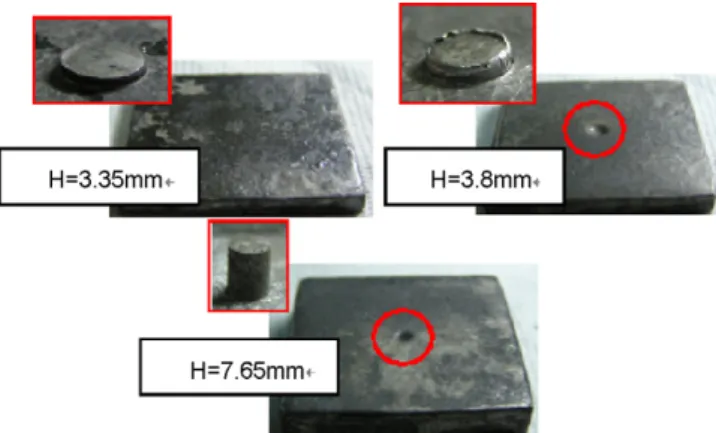
In order to validate the finite element analysis, two sets of tooling were designed and manufactured to perform the actual press forging processes. The electrical heating device was embedded in the tooling to heat both the tooling and the sheet blank to an elevated temperature. The tooling was mounted on a universal testing machine to conduct the experiments with graphite as the lubricant. The AZ31 sheets with thickness of 1.8 and 3 mm were used for specimens. The deformed spec-imens with 3 mm thick sheet blank and various embossment heights formed at 300◦C are shown inFig. 6, the embossment radius being 2 mm. It is seen in Fig. 6 that the flow-through appears when the embossment heights are equal to or larger than 3.8 mm. The flow-through is also observed in specimens with different embossment radii and blank thicknesses.Fig. 7shows the comparison between the experimental data and the finite element simulation results of the embossment heights at which the flow-through appears. As seen inFig. 7, the finite element simulation result agrees with the experimental data for the spec-imen with 1.8 mm thick blank, but predicts a larger embossment height than that of experimental data for 3 mm thick speci-men. However, the difference is not significant and the trend is consistent.
Fig. 6. The deformed specimens with various embossment heights.
Fig. 7. Embossment heights obtained from simulations and experiments with different blank thicknesses.
7. Concluding remarks
The flow-through phenomenon occurred in the press forging of AZ31 magnesium-alloy sheets was examined by the finite element analysis and validated by the experiments performed in the present study. The material properties tests suggest that 300◦C could be an effective forming temperature for the press forging of AZ31 magnesium-alloy sheets. In the finite element analysis, the convergence tests performed in the present study confirm that the element size less than one-tenth of the emboss-ment radius is required for both 2-D and 3-D finite eleemboss-ment meshes to simulate the appearance of flow-through. Simula-tions with elements around the embossment having a larger size may not detect the occurrence of flow-through that is sup-posed to happen. The finite element simulation results also reveal that the formation of flow-through is mainly due to the insuffi-cient material in the neighborhood of the embossment. Hence, the blank thickness and the dimension of embossment are the major parameters affecting the occurrence of flow-through. It further suggests that the flow-through defect may be improved by increasing the blank thickness around the embossment locally by a preforming process instead of using a thicker blank. The limit curves for the occurrence of flow-through established in the present study can be used to predict if the flow-through would occur based on the blank thickness, embossment radius and height chosen. These curves provide an important guideline for the press forging design.
Acknowledgements
The authors would like to thank the National Science Council of the Republic of China for financially supporting this research under the Contract No. NSC-89-2212-E-002-147 which makes the experimental work possible. They also would like to thank the Chung-Shan Institute of Science and Technology for provid-ing the AZ31 magnesium-alloys for experiments. The help from the Scientific Forming Technologies Corporation in running the DEFORM program is highly appreciated as well.
References
[1] H. Watanabe, H. Tsutsui, T. Mukai, M. Kohzu, S. Tnabe, K. Higashi, Deformation mechanism in a coarse-grained Mg–Al–Zn alloy at elevated temperatures, Int. J. Plast. 17 (2001) 387–397.