國 立 交 通 大 學
資 訊 工 程 學 系
博
士
論
文
網路多媒體服務之通話控制
Call Control for IP Multimedia Service
研 究 生:許孟達
指導教授:林一平 博士
張明峰 博士
網路多媒體服務之通話控制
Call Control for IP Multimedia Service
研 究 生:許孟達 Student:Meng-Ta Hsu 指導教授:林一平 博士 Advisor:Dr. Yi-Bing Lin
張明峰 博士 Dr. Ming-Feng Chang 國 立 交 通 大 學 資 訊 工 程 學 系 博 士 論 文 A Dissertation Submitted to
Department of Computer Science College of Computer Science National Chiao Tung University in Partial Fulfillment of the Requirements
for the Degree of Doctor of Philosophy
in
Computer Science
January 2007
Hsinchu, Taiwan, Republic of China
網路多媒體服務之通話控制 學生:許孟達 指導教授:林一平 博士 張明峰 博士 國立交通大學資訊工程學系 摘 要 這幾年來,有很多的力量正驅使著系統供應商提供整合的服務。第一,消費者 希望在各式各樣的機器上面可以享受到統一的服務。第二,消費者希望可以不管 使用的是哪一種接取服務,不管是 WiFi,3G,Ethernet,WiMax,ADSL 或 CABLE, 都能享受到同樣的服務內容。第三,有線系統業者的利潤正在降低,因此他們必 須開始在無線的領域尋找機會,而無線系統業者的成長速度減慢,也使他們開始 探索如何擴大市場。最後,無線與有線業者之間的競爭將會驅使網路服務邁向整 合,而網際網路上的某些語音服務的成功案例,如 Yahoo! Messenger 和 Skype 等,則使得網際網路應用在網路服務邁向整合的過程中佔了舉足輕重的角色。
由於使用者對行動通訊需求越來越高, 他們希望在任何地方都能無線的連接 Internet。3GPP 所定義的 IP Multimedia Subsystem (IMS) 因此而變得更加重 要。本論文中,我們分別就網路多媒體服務的各層面討論設計的議題。在網路電 話的整合網路中,我們提出了一個整合的架構稱為 Integrated Call Agent (iCA)。iCA 整合了網路通訊中的 Media Gateway Control Protocol (MGCP)、 Session Initiation Protocol (SIP) 與 H.323 三個主要的協定,讓使用者可以 在整合的服務中沒有障礙的互通。我們參考 Intelligent Network (IN) 並提出 了很彈性的架構,讓將來整合進更多協定成為可能並且所花的心力降到最低。
針對使用者的身分認證問題,3GPP 制定了 two-pass authentication 程序, 分別為 General Packet Radio Service (GPRS) 網路以及 IMS 網路認證使用者。 我們發現在 two-pass authentication 中有許多重覆的步驟,因此在論文中我們
提出了 one-pass authentication 的方法,以 GPRS 網路執行相同的認證程序, 但 IMS 網路以簡化的方法在使用者註冊過程完成認證。我們證明 one-pass authentication 可以正確的認證使用者,同時省下 50%的訊息交換。 在網路多媒體服務中的服務平台中,我們探討了 SIP 基礎的網路電話客服中心 的設計與實作,並且提出了等待時間的演算法。我們設計了兩個評量預測準確度 的方法並且發展了一個模擬模型來測量演算法的準確度。我們發現所提出的演算 法可以有效的控制使用者等待超時的機率。 以上的研究成果提供讀者在研究網路多媒體服務的通話控制以及身分認證的 議題上,可供參考之基礎。
關鍵字: 第三代行動通訊、Universal Mobile Telecommunications System (UMTS)、 多媒體子系統、身分認證、Session Initiation Protocol (SIP)、通話控制、Media Gateway Control Protocol (MGCP)、等待時間預測。
Call Control for IP Multimedia Service
Student: Meng-Ta Hsu Advisors: Dr. Yi-Bing Lin Dr. Ming-Feng Chang Department of Computer Science
National Chiao Tung University ABSTRACT
In recent years, there are many forces urging operators to provide the converged services. First, customers hope to enjoy unified services on different type of devices. Second, users want to have uniform services and contents regardless of the kind of underlying access network being used, such as WiFi, 3G, ethernet, WiMax, ADSL, or cable. Third, fixed network providers’ profit is reducing, so they must begin to look for the opportunities in wireless domain. And wireless operators’ speed of growth slows down, makes them begin to explore how to expand their markets. Finally, the competition between the fixed and wireless carriers will drive the network service toward convergence, and some successful cases of Internet telecommunications services such as Yahoo! Messenger and Skype, etc., make Internet Protocol (IP) applications take very important role during the process toward convergence.
As consumers become increasingly mobile, they will demand wireless Internet access from everywhere. In keeping with these requirements of end users, IP Multimedia Subsystem (IMS) standards based on the 3GPP UMTS become more and more important. In the IMS system, we propose an integrated call agent of the converged VoIP network. We presente a simple, flexible framework for the interworking functions of VoIP protocols such as Media Gateway Control Protocol (MGCP), Session Initiation Protocol (SIP) and H.323 base on Intelligent Network (IN).
In UMTS two-pass authentication, many steps in the General Packet Radio Service (GPRS) authentication and IMS authentication are duplicated. Therefore, we propose an one-pass authentication procedure, in which only the GPRS authentication procedure is performed. In the IMS network, the authentication is implicitly executed in the IMS registration. We formally prove that the IMS user is correctly authenticated, and the one-pass authentication saves up to 50% of the IMS registration/authentication traffic.
In the service platform of IP multimedia services, we describe the design and implementation of a SIP-based VoIP call center with waiting time prediction. The SIP-based plug-in modular call center architecture and detailed message flows are elaborated. We propose two output measures and develop a discrete event simulation model to investigate the performance of the waiting time prediction algorithm for the call center.
These research results presented in this dissertation can be viewed as a useful foundation for further study in call control for IP multimedia services and authentication.
Key Words: Third Generation (3G), Universal Mobile Telecommunications System
(UMTS), IP Multimedia Subsystem (IMS), authentication, Session Initiation Protocol (SIP), call control, Media Gateway Control Protocol (MGCP), waiting time prediction, Call Session Control Function (CSCF).
Acknowledgement
I would like to express my sincere thanks to my advisors, Prof. Yi-Bing Lin and Prof. Ming-Feng Chang. Without their supervision and perspicacious advice, I can not complete this dissertation. Special thanks to my committee members, Dr. Sheng-Lin Chou, Prof. Han-Chieh Chao, Dr. Herman Chung-Hwa Rao, Prof. Chu-Sing Yang, Prof. Wen-Nung Tsai, and Prof. Hsi-Lu Chao for their valuable comments. Thanks also to the colleagues in Laboratory 117 and 118.
I also express my appreciation to all the faculty, staff and colleagues in the Department of Computer Science and Information Engineering. In particular, I would like to thank Prof. Phone Lin, Prof. Ai-Chun Pang, Dr. Yuan-Kai Chen, Prof. Wei-Zu Yang, Prof. Shun-Ren Yang, Prof. Pei-Chun Lee for their friendship and support in various ways.
Finally, I am grateful to my family, my dear father, mother, sister, Joan Hsu, my little baby, and friends for their encouragement and support during these years.
Contents
Abstract in Chinese i
Abstract in English iii
Acknowledgement v Contents vi List of Tables ix List of Figures x Abbreviation xii 1 Introduction . . . 1 1.1 IP Multimedia Subsystem . . . 2
1.2 An Integrated Call Agent of the Converged VoIP Network . . . 7
1.3 One-Pass GPRS and IMS Authentication Procedure for UMTS . . . 8
1.4 A SIP-based Call Center with Waiting Time Prediction . . . 10
2 An Integrated Call Agent of the Converged VoIP Network . . . 12
2.1 Introduction . . . 13
2.1.1 VoIP protocols . . . 13
2.1.2 Interoperation . . . 16
2.2 IN Basic Call State Model . . . 17
2.3.1 Mapping of VoIP protocol messages to the BCSM messages . . . 22
2.3.2 H.323 slow-start . . . 25
2.4 System Implementation and Result . . . 27
2.5 Conclusions . . . 29
3 One-Pass GPRS and IMS Authentication Procedure for UMTS . . . 31
3.1 Introduction . . . 31
3.2 3GPP Two-Pass Authentication . . . 35
3.3 One-Pass Authentication Procedure . . . 41
3.4 Correctness of the One-Pass Procedure . . . 46
3.5 Summary . . . 50
4 A SIP-based Call Center with Waiting Time Prediction . . . 51
4.1 Introduction . . . 51
4.2 Automatic Call distributor Module for SER . . . 53
4.3 Call Center Message Flows . . . 56
4.4 The Waiting Time Prediction Algorithm . . . 63
4.4.1 Enhanced Whitt’s Algorithm . . . 64
4.4.2 Performance Evaluation . . . 66
4.5 CallBack Mechanism . . . 69
4.5.1 The PTN CallBack Mechanism . . . 71
4.5.2 Discussions . . . 72
4.6 Conclusions . . . 73
5 Conclusions and Future Work . . . 74
5.1 Summary . . . 74
Reference . . . 77 Curriculum Vita . . . 82 Publication List . . . 83
List of Tables
3.1 Identical Steps in GPRS and IMS Authentications . . . 39 3.2 Comparing the One-Pass and the Two-Pass Authentication Procedures in
List of Figures
1.1 UMTS All-IP Network Architecture . . . 4
2.1 MGCP architecture . . . 16
2.2 IN architecture . . . 18
2.3 Simplified IN BCSMs . . . 19
2.4 Components developed for a general VoIP gateway . . . 20
2.5 A SIP/H.323 gateway . . . 20
2.6 A converged VoIP network using gateways . . . 21
2.7 A converged VoIP network managed by integrated call agents . . . 22
2.8 An example of H.323 and MGCP interworking using 2 ICAs . . . 22
2.9 Mapping VoIP messages to BCSM messages . . . 24
2.10 BCSMs for the H.323 slow-start . . . 26
2.11 Call flow of H.323 (slow-start) and SIP interworking . . . 27
2.12 Components used in our platform . . . 29
2.13 Call establishment delays . . . 29
3.1 UMTS architecture for packet switched service domain . . . 33
3.2 Message flow for 3GPP GPRS authentication . . . 35
3.3 Message flow for 3GPP IMS authentication . . . 37
3.4 Illegal IMS registration . . . 40
3.5 IMS registration (one-pass authentication) . . . 42
4.1 VoIP-based call center . . . 52
4.2 The proposed call center architecture . . . 54
4.3 The FSM State Transition Diagram of ACD . . . 56
4.4 The select_agent() function . . . 58
4.5 The set_agent_state() function . . . 59
4.6 Normal call setup message flow . . . 60
4.7 The flow diagram for the agent dispatcher . . . 61
4.8 Message flow when all agents are busy . . . 62
4.9 The δ and θ performances (n=80, µ=0.05/sec, γ=0.01) . . . 67
4.10 The δ and θ performances when customers may be impatient . . . 69
Abbreviation
The abbreviations used in this dissertation are listed below.
3GPP: 3rd Generation Partnership Project ACD: Automatic Call Distributor
AKA: Authentication and Key Agreement ALG: Application Level Gateway
AuC: Authentication Center BCSM: Basic Call State Model CA: Call Agent
CS: Circuit-Switched
CSCF: Call Session Control Function DTMF: Dual Tone Multi-Frequency FSM: Finite State Machine
GGSN: Gateway GPRS Support Node GMM: GPRS Mobility Management GPRS: General Packet Radio Service
GSM: Global System for Mobile Communications HLR: Home Location Register
HSS: Home Subscriber Server ICA: Integrated Call Agent
IMPI: IP Multimedia Private Identity IMS: IP Multimedia Subsystem
IMSI: International Mobile Subscriber Identity IN: Intelligent Network
ISIM: IMS Subscriber Identity Module IVR: Interactive Voice Response MAP: Mobile Application Part MGC: Media Gateway Controller
MGCP: Media Gateway Control Protocol MS: Mobile Station
OSA: Open Service Access P2P: Peer-to-Peer
PBX: Private Branch Exchange PCM: Pulse-Code Modulation PS: Packet-Switched
PSTN: Public Switched Telephone Network PTN: Private Telecommunications Network RAN: Radio Access Network
RAS: Registration Administration Status RGW: Residential Gateway
RTP: Real-time Transport Protocol SCP: Service Control Point
SDP: Session Description Protocol SER: SIP Express Router
SGSN: Serving GPRS Support Node SIP: Session Initiation Protocol SS7: Signaling System Number 7 SSP: Service Switching Point UE: User Equipment
UMTS: Universal Mobile Telecommunications System USIM: Universal Subscriber Identity Module
UTRAN: UMTS Terrestrial Radio Access Network VoIP: Voice over IP
Chapter 1
Introduction
In recent years, there are many forces urging telecom operators to provide the converged services by combining Voice over IP (VoIP) services with advanced data and information services. First, customers hope to enjoy unified services on different type of devices, such as cell phones, personal digital assistants (PDA), smart phones, laptop, or desktop PCs. Second, users want to have unified services regardless of the kind of underlying access network being used, such as WiFi, 3G, Ethernet, WiMax, ADSL, or cable. Third, fixed network providers’ profit is reducing, so they must begin to look for the opportunities in wireless domain. Furthermore, mobile operators’ speed of growth slows down, and they begin to explore opportunities to expand their markets. Finally, the competition between the fixed and mobile carriers will drive the network service toward convergence, and some successful cases of Internet telecommunications services, such as Yahoo! Messenger, Skype, etc., make Internet Protocol (IP) applications take an important role during the process toward convergence.
The Third Generation (3G) and Beyond the 3G (B3G) mobile systems are developed in order to offer Internet access to mobile users. The Universal Mobile Telecommunications System (UMTS) [25, 27] standardized via the 3GPP represents an evolution in terms of capacity, data speed and new service capabilities from second
generation mobile networks such as Global System for Mobile Communications (GSM) and General Packet Radio Service (GPRS) [25]. Today, more than 122 3G/UMTS networks using WCDMA technology are operating commercially in 55 countries [52].
The Third Generation Partnership Project (3GPP) [53] IP Multimedia Subsystem (IMS) [21] is a standardized next generation networking architecture for telecom operators that want to provide multimedia services over mobile and fixed networks. It supports VoIP communications based on a 3GPP standardized implementation of Session Initiation Protocol (SIP) [6], and runs over the standard Internet Protocol (IP). Although the IMS was originally specified for 3G mobile networks, it can also be provided on any IP-based networks, such as WiFi, corporate enterprise LANs, and the public Internet.
1.1 IP Multimedia Subsystem
The 3GPP proposed the UMTS all-IP architecture to integrate IP and mobile technologies [28]. This architecture evolved from GPRS, UMTS Release 1999 (UMTS R99), and UMTS Release 2000 (UMTS R00). UMTS Release 2000 has been split up into Release 4 and 5. Release 4 introduces a next-generation network architecture for the circuit-switched (CS) domain. Release 5 introduces the IP Multimedia Subsystem (IMS) [21] on top of the packet-switched (PS) domain. The deployment of all-IP network has the following advantages. First, mobile operators could benefit from all existing Internet applications, as well as from the introduction of new services. Second, this evolution allows telecommunications operators to use a common platform (for example, IP) to provide CS and PS domain services, and reduce deployment and operating costs. Third, the new generation of applications will be developed in an all-IP environment, which shortens the distance between mobile and the Internet.
As consumers become increasingly mobile, they will demand wireless Internet access from everywhere. In keeping with these requirements of end users, IMS standards based on the 3GPP UMTS become more and more important. IMS uses Session Initiation Protocol (SIP) [6] defined by IETF and adds extensions for the requirements of mobility to offer multimedia session negotiation and session management over IP. IMS provides an architecture that is independent of the underlying access network, such independency is very important for convergence. Now almost every access network is being enabled to work with an IMS core, including DSL, cable, WiFi, GPRS, WCDMA, or any emerging technology, such as WiMAX. The 3GPP2 group [54] also constructs their Multimedia Domain (MMD) solution based on the IMS network. This will allow CMDA2000 based access network to provide more advanced third generation mobile services.
IMS not only provides more innovative services for any type of media session (e.g. voice, video, text, etc.), it also provides the functionality to simultaneously combine CS and PS domain services, and allows sessions to be dynamically modified “on the fly” (e.g. adding a video component to an existing voice session). These capabilities enable IMS to provide a number of new user-to-user and multi-user applications such as enhanced voice services, video telephony, chat, Push-to-talk over Cellular (PoC) [55] and multimedia conferencing.
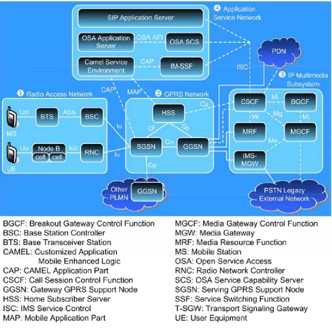
The UMTS all-IP network architecture [56] consists of the following segments: Radio Access Network (RAN; see Figure 1.1(1)) can be UMTS Terrestrial Radio Access Network (UTRAN) or GSM Enhanced Data Rates for Global Evolution (EDGE) Radio Access Network (GERAN).
GPRS Core Network (Figure 1.1 (2)) consists of Serving GPRS Support Nodes (SGSNs) and Gateway GPRS Support Nodes (GGSNs) that provide mobility management and session management. Home Subscriber Server (HSS) is the master
database containing all 3G user subscription data. The HSS consists of the IMS functionality (IMS user database) and the Home Location Register (HLR) functionality required by the PS domain and the CS domain to provide support for call handling entities. The Iu interface between UTRAN and SGSN is IP based. SGSN and GGSN communicate with HSS through Gr and Gc interfaces, respectively. These two interfaces are based on Mobile Application Part (MAP).
Figure 1.1. UMTS All-IP Network Architecture.
IP Multimedia Subsystem (IMS; Figure 1.1 (3)) is located between the GGSN and the PDN (specifically, the IP networks). In this subsystem, the Call Session Control
Function (CSCF) [21] is a SIP server, which is responsible for call control. Other nodes in the IMS include Breakout Gateway Control Function (BGCF), Media Gateway Control Function (MGCF), and IM-Media Gateway Function (IM-MGW). These nodes are typically used in a VoIP network.
Application and Service Network (Figure 1.1 (4)) supports flexible services through a service platform. The IMS network architecture will provide a separation of service control from call/connection control, and the applications are implemented in dedicated application servers that host service-related databases or libraries. The IMS Service Control (ISC) interface is the IETF SIP protocol with extensions for service control. The 3GPP defines three possible alternatives to provide flexible and global services:
z SIP Application Server: The SIP application services are either developed by the mobile operators or from trusted third parties.
z IM-Service Switching Function (IM-SSF) and CAMEL Service Environment (CSE): This server will be used by the mobile operator to provide CAMEL services to the IMS users. The legacy CS domain Services are provided via the CSE platform.
z Open Service Access (OSA) Service Capability Server (SCS) and OSA Application Server: This server will be used to give third parties controlled access to the operator’s network, and enable third parties to run their own applications (in the third-party application servers) using the IMS capabilities of the operator’s network.
In the IMS network, a CSCF can be proxy, serving, or interrogating. The Proxy CSCF (P-CSCF) is the first contact point within the IMS for a User Equipment (UE). The P-CSCF may be located in the home or visited network. The P-CSCF ensures that registration of the user is passed to the correct home network and that SIP session
messages are passed to the correct Serving CSCF (S-CSCF) once registration has occurred. The P-CSCF is an important function as it is in the position to detect services. The S-CSCF is the function that registers the user and provides service to them. It performs routing and translation, provides billing information to mediation systems, maintains session timers, and interrogates the HSS to retrieve authorization, service triggering information and user profile. In short, it is the brain of the IMS. Interrogating CSCF (I-CSCF) is the function that is able to determine the S-CSCF with which a user should register. This is achieved by querying the HSS, which checks that the user is allowed to register in the originating network and returns an S-CSCF name and capability if this is the case. The I-CSCF is then able to contact the S-CSCF with the register. The I-CSCF function can be removed from the signaling path once it has been used to establish which S-CSCF is in use. The exception to this is if the THIG (Topology Hiding Inter-network Gateway) function of the I-CSCF is being used.
In this dissertation, we study the UMTS all-IP network in three parts. First, an integrated Call Agent of the converged VoIP network is presented. This topic focuses on the IMS network components (Figure 1.1 (3)) and discusses the interworking between different VoIP protocols, such as SIP, MGCP and H.323. After the IMS network and the VoIP protocols interworking are elaborated, we study the correlation between IMS and GPRS networks. We find the authentication procedures of GPRS and IMS networks are almost the same. To eliminate the redundancy of the authentication procedures, we proposed the one-pass GPRS and IMS authentication procedure for UMTS. This topic discusses the authentication procedure started from the UE of the radio access network (Figure 1.1 (1)) through the GPRS core network (Figure 1.1 (2)) to the IMS network. After the GPRS and IMS networks, we study the application platform of the 3GPP all-IP network architecture. A SIP based call center with waiting time prediction is elaborated. This work focuses on the service platform
(Figure 1.1 (4)) and uses the call center as a SIP application server.
1.2 An Integrated Call Agent of the Converged VoIP
Network
The traditional circuit-switched telecommunication network and the packet-switch data network are converging to a single packet-switched multimedia service network. One important application of the convergence is IP telephony communications, also referred to as VoIP (Voice over IP). In a converged VoIP network such as IMS, media gateways are responsible for connecting packet-switched network with the PSTN network. Media gateway controllers (MGCs) also referred to as Call Agents (CA) perform call control functions and instruct commands to media gateways through the Media Gateway Control Protocol (MGCP) [7]. Other VoIP protocols including SIP and H.323 provides multimedia call control over packet-switched network. H.323 is an ITU-T recommendation for multimedia conferencing [4]. It is a protocol umbrella that consists of many standards, including Q.931 call control protocol, H.225 registration and administration, and H.245 media negotiation. SIP has been standardized by IETF for interactive communication sessions between users. It as well is chosen as the IMS Service Control (ISC) interface between the CSCF and the service platform in the UMTS IMS network. SIP is a text-based request-response architecture similar to HTTP. Since SIP is simpler and more flexible then H.323, many consider SIP a powerful alternative to H.323. H.323 and SIP utilize Real-time Transport Protocol (RTP) [36] to transmit real-time packets over the Internet.
To provide interworking functions in the converged VoIP network and enable devices using different protocols to communicate, gateways are needed to translate
messages between different protocols. Vemuri described an inter-operation model called SPHINX (SIP, H.323 and IN interworking) [11] where H.323 and SIP terminals can access IN services. In addition, an SIP-H323 gateway is a byproduct of this inter-operation model based on the half-call state model of the IN. Gurbani and Rastogi [14] and Haerens [15] suggested ways to map the call control of SIP to IN, but they did not support the H.323 slow-start call setup. Agrawal, Schulzrinne and Singh specified the requirements for SIP-H.323 interworking [12, 13]. However, no work has been done on interoperating all VoIP protocols in a simple and flexible framework.
In this topic, we present an integrated call agent architecture that supports the interworking function of VoIP protocols (SIP, H.323, MGCP and MEGACO) using the basic call state model in Intelligent Network. The interworking function translates messages of the VoIP protocols and is transparent to the call parties and kept as simple as possible. Furthermore, our design supports inter-CA communications using SIP in a straightforward manner.
1.3 One-Pass GPRS and IMS Authentication
Procedure for UMTS
The packet data services of the UMTS PS core network are provided by the SGSN via UTRAN. The SGSN connects to the external data network through the GGSN. Furthermore, the SGSN communicates with the home subscriber server (HSS) and the authentication center (AuC) [56] to retrieve subscriber data and authentication information of an MS. When an MS performs location update or tries to attach onto the GPRS service, the SGSN may perform GPRS authentication to the user. The authenticating parties are HSS in the home network and the universal subscriber identity module (USIM) in the MS. GPRS authentication consists of two major
procedures:
z Distribution of authentication information: The SGSN retrieves an array of authentication vectors (AVs) of the MS from the AuC.
z Authentication and key agreement (AKA): This procedure uses the AV which is obtained from the previous step to perform mutual authentication between an MS and the network by showing knowledge of a pre-shared secret key that is only available in the USIM of the MS and in the AuC.
The detail of the GPRS authentication will be elaborated in chapter 3. In addition to GPRS authentication, it is necessary to authenticate the MS before it can access IMS services. Without IMS authentication, a mobile user who passes the GPRS authentication can easily fake being another IMS user. The IMS authentication procedure is performed by the IMS registration which is invoked from the MS through the P-CSCF to the S-CSCF. Since the IMS information is delivered through the GPRS transport network, a UMTS mobile station must activate GPRS packet data protocol (PDP) context [20] before it can register to the IMS network. The 3GPP specifications define mutual authentication mechanisms [19] in both the GPRS network and the IMS. Although both GPRS and IMS authentications are necessary, most steps in this 3GPP “two-pass” authentication procedure are duplicated. G. Horn, D. Kröselberg, and K. Müller [57] surveyed the security architecture of the IMS including user specific features protecting the access of the IMS user, such as AKA when a user registers, integrity protection of IMS access signaling and independent protection of SIP signaling in the IMS core network. Y.-B. Lin and Y.-K. Chen [23] surveyed the authentication procedure of UMTS and proposed an algorithm to reduce the authentication signaling traffic. However, no work has been done on the reduction of the duplicated two-pass authentication procedure of GPRS and IMS.
Based on our observation, we propose a one-pass authentication procedure that only needs to perform GPRS authentication. At the IMS level, authentication is implicitly performed in IMS registration. Our approach may save up to 50% of the IMS registration/authentication traffic, as compared with the 3GPP two-pass procedure. We formally prove that the one-pass procedure correctly authenticate the IMS users.
1.4 A SIP-based Call Center with Waiting Time
Prediction
A call center is a centralized office that answers incoming telephone calls from customers or makes outgoing telephone calls to customers. When all agents are busy, the arriving customer calls have to wait in a queue. A waiting customer will be served after an agent becomes available. To improve customer satisfaction, it is essential to inform the waiting customers of predicted delays before they can be served. Whitt [43, 44] proposed an algorithm to predict the waiting time for customers. It is important to evaluate the accuracy of prediction, which was not mentioned in [43].
In this topic, we propose a plug-in modular architecture for an Internet call center with waiting time prediction. We implement this plug-in module in the SIP Express Router (SER) [40] platform. The SER is a high-performance, configurable, free SIP server. It can act as a SIP registrar, proxy or redirect server. The plug-in SER module called Automatic Call Distributor (ACD) module consists of five components: the agent dispatcher, the queue manager, the agent state manager, the Interactive Voice Response (IVR) and the ACD database.
The ACD module maintains a status record for each of the agents. The record is accessed by the agent state manager. A five-state Finite State Machine (FSM) is
associated with the record. We describe the detailed functionality and the interfaces of each component in Chapter 4.
Then we propose two output measures and develop a discrete event simulation model to investigate the performance of the waiting time prediction algorithm for the call center. Our study indicates that the waiting times can be more accurately predicted when the call arrival rate is large.
This dissertation is organized as follows. Chapter 2 presents an integrated Call Agent of the converged VoIP network. Chapter 3 describes the one-pass GPRS and IMS authentication procedure for UMTS. In Chapter 4, we describe a SIP based call center with waiting time prediction. Chapter 5 concludes this dissertation and
Chapter 2
An Integrated Call Agent of the
Converged VoIP Network
The traditional circuit-switched telecommunication network and the packet-switched data network are converging to a single packet-switched network. One important application of the converged network is telephony communications, also referred to as VoIP (Voice over IP). Call signaling protocols, such as H.323, SIP and MGCP, have been developed to support VoIP communications. To enable devices using different VoIP protocols to communicate, gateways are needed to translate messages of one protocol to messages of another. In this chapter, we present a simple, flexible framework for this interworking function. The framework is based on a half-call model where a call is controlled by two half-call finite state machines (FSMs), one representing the state of the caller and the other representing the state of the callee. The interworking function has been implemented such that the caller FSM of one VoIP protocol can interact with the callee FSM of any VoIP protocol. The development effort of the interworking function is minimized since only two half-call FSMs for each VoIP protocol are needed and they can be developed independently as long as the design conforms to the same interface specification. We have developed an integrated call agent
(ICA) that contains the half-call FSMs of H.323, SIP and MGCP. Calls between devices using these VoIP protocols can be set up, maintained and terminated by the ICAs.
2.1 Introduction
The PSTN (Public Switched Telephone Network) has provided reliable voice communication for decades. A telephone call to anyone in the world can be established in seconds, and the voice quality is good in general. Voice waveform transmitted in the PSTN is encoded using PCM (pulse-code modulation, G.711 A-law and u-law, both 64kbps) technique. To establish a telephone call between two parties, a dedicated link needs to be set up, and the link has to be torn down when the call terminates. This work is performed by telephone switches exchanging standard signaling, such as ISUP (Integrated Services Digital Network User Part).
2.1.1 VoIP protocols
As the Internet becomes overwhelmingly widespread, transporting voice communication traffic using the Internet Protocol (IP) provides advantages over the traditional PSTN. This is often referred to as IP telephony or VoIP (Voice over IP). VoIP can use sophisticated speech codecs, such as G.723.1 and G.729 [1], to reduce the bandwidth required for a call. VoIP communications use RTP/RTCP to transport voice packets over IP networks [2,3]. To establish a call, the two parties
involved should negotiate the codec and the RTP/RTCP ports used for the call, as well as exchange messages to set up and terminate the call. H.323 and SIP are two existing VoIP signaling protocols. Both are designed to support the setup, communication capacity exchange and tear-down of a VoIP call.
H.323 is an ITU-T recommendation for multimedia conferencing over packet-switched networks [4]. It is a protocol umbrella that consists of many standards, including Q.931 call control protocol, H.225 registration and administration, and H.245 media negotiation. It is widely used nowadays; NetMeeting of Microsoft and VoIP products from Cisco all support H.323 multimedia communications over packet-switched networks. H.323 also defines a gatekeeper as a manager and arbiter over a network. The gatekeeper is an optional entity in charge of endpoint registration, address translation, and bandwidth assignment. An H.323 endpoint can make a direct or gatekeeper-routed call. One of the major criticisms against H.323 is the time and complexity involved in setting up a call; H.323 version 1 uses multiple stages to exchange signaling and media capabilities. Moreover, messages are transported using TCP, which requires additional session set-up time. Recent H.323 versions can include both signaling and media capabilities in a single message transmitted by UDP, which eliminates the additional round-trip time for TCP handshake [5]. However, with too many options, H.323 still has compatibility problems for the products from different providers.
Session Initiation Protocol (SIP) has been standardized by IETF for initiating interactive communication sessions between users [6]. It can be used to establish Internet telephony calls. SIP is a lightweight protocol, which uses only six commands for session control. With early media capability exchange feature, a
SIP terminal can issue only one command, INVITE, to set up a call. Therefore, it is faster than H.323 in call establishing. SIP is a text-based request-response architecture similar to HTTP. Since SIP is simpler then H.323, many consider SIP a powerful alternative to H.323
To enable communications between VoIP users and PSTN users, gateways between the PSTN and IP-based networks are needed. Since the signaling used in the VoIP networks and the PSTN are different, and the voice media are transmitted in different formats, the gateways have to perform two functions: signaling conversion and media conversion. The two functions can be carried out in two separated entities: MGC (Media Gateway Controller) and MG (Media Gateway). An MGC (also referred to as a CA, Call Agent) performs the signaling conversion function, and an MG performs the media conversion function. A standardized protocol can be used between an MGC and MGs.IETF proposed the MGCP (Media Gateway Control Protocol) architecture depicted in Figure 1 [7]. MGCP is a master-slave protocol. A CA is a master and has control over several MGs; an MG acts as a slave and is kept simple and passive. A CA also performs the call control function as a gatekeeper in H.323, but has much tighter control. A CA instructs an MG to establish, maintain, and terminate a call between a VoIP terminal and an endpoint in the PSTN. MGCP is based on a centralized network infrastructure. To serve to a wide area network, a group of CAs need to coordinate, but MGCP does not specify how the CAs interact. Signaling used in inter-CA communications can be SIP or ISUP. MGCP describes the media capability and parameter using SDP (Session Description Protocol, [8]). Recently Megaco (or H.248), an enhanced version of MGCP, is promoted jointly by the IETF and ITU-T [9].
MG CA MGC P RTP Internet PSTN MG CA MGC P RTP Internet Internet PSTNPSTN Figure 1. MGCP architecture.
2.1.2 Interoperation
Since H.323 and SIP are expected to co-exist in the near future, gateways between H.323 and SIP terminals are needed for the interworking function between H.323 and SIP. EURESCOM proposed a project for providing IN functionality for H.323 telephony calls [10]. Vemuri described an inter-operation model called SPHINX (SIP, H.323 and IN interworking) where H.323 and SIP terminals can access IN services [11]. In addition, an SIP-H323 gateway is a byproduct of this inter-operation model based on the half-call state model of the IN. Agrawal, Schulzrinne and Singh [12,13] specified the requirements for SIP-H.323 interworking. Gurbani and Rastogi [14] and Haerens [15] suggested ways to map the call control of SIP to IN, but they did not support the H.323 slow-start call setup. Ackermann, et al., have implemented a sip-h323 gateway as a basis for supplementary service interworking [16]. They use a dedicated call model that transfers H.323 messages to SIP messages, and vice versa. Singh and Schulzrinne have presented a Columbia InterNet Extensible Multimedia Architecture (CINEMA) where MGCP and H.323 can be interworking through SIP [17]. Nevertheless, it is difficult to modify this call model to cooperate with other VoIP protocols.
However, no work has been done on interoperating all VoIP protocols in a simple and flexible framework. In this chapter we present an integrated call agent architecture that supports the interworking function of VoIP protocols (SIP, H.323, MGCP and MEGACO) using the basic call state model in Intelligent Network [18]. The interworking function translates messages of the VOIP protocols. The translation is transparent to the call parties and kept as simple as possible. Furthermore, our design supports inter-CA communications using SIP in a straightforward manner. The rest of the chapter is organized as follows. Section 2.2 briefly describes the IN basic call state model. Section 2.3 presents the system design and the implementation issues. Implementation issues and results are discussed in Section 2.4. Conclusions are given in Section 2.5.
2.2 IN Basic Call State Model
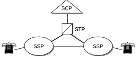
An intelligent network (IN) separates the service logic from the switching function in the telecommunications network; the service intelligence is placed in computer nodes that are distributed throughout the network. This provides the network operators with the means to develop and control services more efficiently. New capabilities can be rapidly introduced and customized for the network. A simple IN architecture is depicted in Figure 2. A service switching point (SSP) is an IN-capable switching system dealing with the call control functions that establish, maintain, and clear a call. In addition, it detects user requests for IN-based services and queries a service control point (SCP) to determine how the call should be handled. The SCP contains the service logic to provide the IN services.
STP SCP SCP SSP SSP SSPSSP STP SCP SCP SSP SSP SSPSSP Figure 2. IN architecture.
The basic call control function of an SSP is supported by a finite state machine (FSM) called basic call state model (BCSM). The BCSM consists of point in calls (PICs), detection points (DPs), and events. PICs represent the switching activities or states that a call goes through from call origination to termination. DPs are states at which transfer of control from the SSP to the SCP can occur. Events are messages exchanged between BCSMs, and trigger state transitions of the BCSMs.
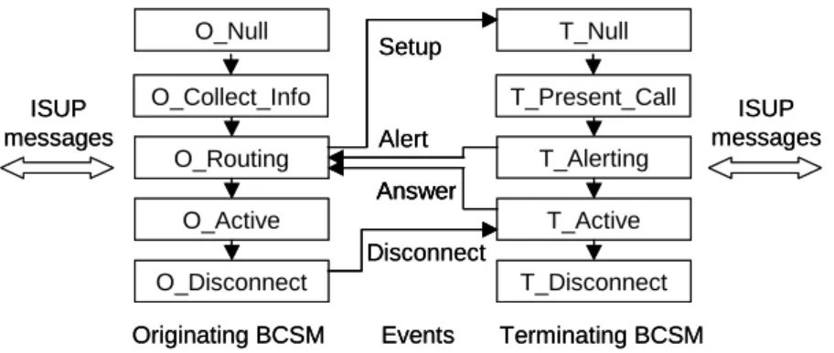
Figure 3 shows that the BCSM is based on half-call model; a call model consists of two half-call models: the originating BCSM (O_BCSM) and terminating BCSM (T_BCSM). The O_BCSM represents the states associated with the call originating party; the T_BCSM represents the states associated with the call terminating party. Note that the originating and terminating BCSMs interact with the call parties using ISUP messages. The call control functions are performed through the exchange of events between the O_BCSMs and T_BCSMs. These events include Setup, Alert, Answer, Disconnect, Busy, No-Answer, and Abandon. For details, the readers are referred to [18].
O_Null O_Routing O_Active O_Disconnect T_Null T_Active T_Alerting T_Disconnect Originating BCSM Terminating BCSM ISUP messages Setup Alert Answer Disconnect Events
O_Collect_Info T_Present_Call ISUP messages O_Null O_Routing O_Active O_Disconnect T_Null T_Active T_Alerting T_Disconnect Originating BCSM Terminating BCSM ISUP messages Setup Alert Answer Answer Disconnect Events
O_Collect_Info T_Present_Call ISUP messages
Figure 3. Simplified IN BCSMs.
2.3 System Architecture
We proposed a simple systematic way to implement the interworking function (IWF) between VoIP protocols. There are two major functions in the IWF: call routing function and call control function. The call routing function locates the called party by querying a location database so that the call request can be delivered. How to locate a user is beyond the scope of this paper; we assume that a user location database exists. The call control function sets up and maintains the call by translating messages between two VoIP protocols.
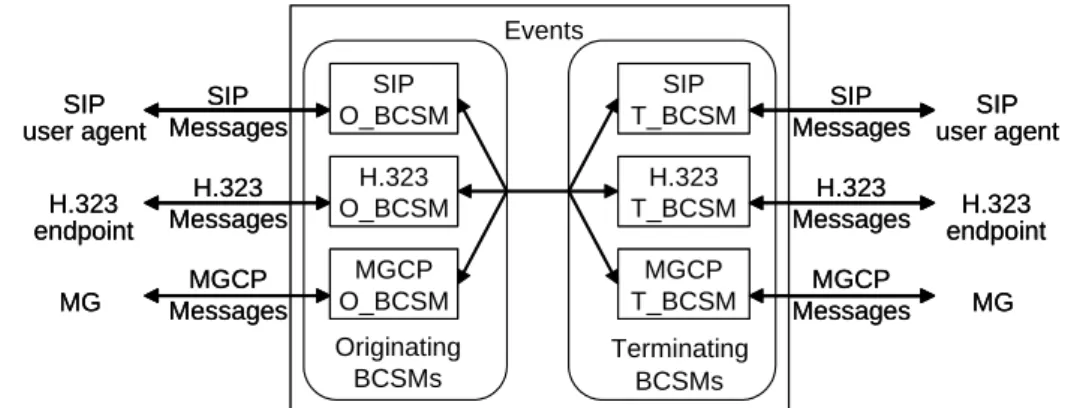
The call control function can be implemented using the BCSMs. For each VoIP protocols, its messages are mapped to the messages of the BCSMs. An interworking gateway of two VoIP protocols can be implemented by combining the BCSMs of the VoIP protocols. Therefore, an O_BCSM of one VoIP protocol and a T_BCSM of another VoIP protocol can interact through the exchange of a set of unified events based on the IN half-call model. Figure 4 shows the six BCSMs of three major VoIP protocols for a general gateway design. Note that the events between an O_BCSM and a T_BCSM are protocol independent. This design reduces developing efforts. To interwork n different VoIP protocols, each
protocol needs only one O_BCSM and one T_BCSM (i.e. 2n BCSMs in total), instead of hardcoding n2 messages translation modules between any two protocols.
Originating BCSMs Terminating BCSMs SIP O_BCSM H.323 O_BCSM MGCP O_BCSM SIP T_BCSM H.323 T_BCSM MGCP T_BCSM Events SIP Messages H.323 Messages MGCP Messages SIP Messages H.323 Messages MGCP Messages SIP user agent H.323 endpoint MG SIP user agent H.323 endpoint MG Originating BCSMs Terminating BCSMs SIP O_BCSM H.323 O_BCSM MGCP O_BCSM SIP O_BCSM H.323 O_BCSM MGCP O_BCSM SIP T_BCSM H.323 T_BCSM MGCP T_BCSM SIP T_BCSM H.323 T_BCSM MGCP T_BCSM Events SIP Messages H.323 Messages MGCP Messages SIP Messages H.323 Messages MGCP Messages SIP user agent H.323 endpoint MG SIP user agent H.323 endpoint MG
Figure 4. Components developed for a general VoIP gateway.
A combination of the BCSMs of two VoIP protocols becomes a gateway; the construction of a gateway is to design the BCSMs of the VoIP protocols. Figure 5 shows an example SIP/H.323 gateway. This gateway consists of the BCSMs of SIP and H.323. When a SIP UA originates a call to a H.323 terminal, a SIP O_BCSM receives a SIP INVITE message and issues a Setup event to an H.323 T_BCSM. After being notified by the Setup event, the H.323 T_BCSM sends an H.323 SETUP message to the terminating H.323 endpoint. Subsequent SIP and H.323 messages are exchanged to set up the call through the interaction of the SIP O_BCSM and H.323 T_BCSM. On the other hand, an originating call from a H.323 terminal to a SIP UA can be handled by an H.323 O_BCSM and a SIP T_BCSM. SIP/H323 gateway SIP O_BCSM H.323 T_BCSM SIP T_BCSM H.323 O_BCSM Events H.323 Messages SIP Messages A SIP caller An H.323 callee A SIP callee An H.323 caller SIP/H323 gateway SIP O_BCSM H.323 T_BCSM SIP T_BCSM H.323 O_BCSM Events H.323 Messages SIP Messages A SIP caller An H.323 callee A SIP callee An H.323 caller
Figure 5. A SIP/H.323 gateway.
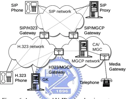
in the same way described above. Figure 6 depicts a converged network using three gateways: SIP/H.323, SIP/MGCP, and MGCP/H.323 gateways. Note that the gateways can share the same BCSMs developed. Moreover, when a new VoIP protocol, such as MEGACO, is added to the converged network, the gateways to MEGACO network use the same BCSMs developed for existing VoIP protocols; only the BCSMs of MEGACO need to be implemented.
SIP/H323 Gateway SIP/MGCP Gateway CA/ MGC Media Gateway Telephone H323/MGCP Gateway GK H.323 Phone SIP Proxy SIP Phone H.323 network SIP network MGCP network SIP/H323 Gateway SIP/MGCP Gateway CA/ MGC Media Gateway Telephone H323/MGCP Gateway GK H.323 Phone SIP Proxy SIP Phone H.323 network SIP network MGCP network
Figure 6. A converged VoIP network using gateways.
To route an originating call, the location of the callee and the signaling protocol that the callee supports must be determined so that a correct T_BCSM can be invoked for messages translation. Solutions to this call routing function are beyond the scope of this paper; we assume that a solution is available. We integrate the call routing function and the BCSMs of all VoIP protocols in an entity called integrated call agent (ICA). The ICA can not only translate messages between VoIP protocols but also act as a H.323 gatekeeper, a SIP proxy/registrar, and a MGCP call agent.
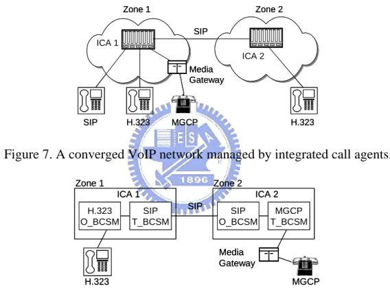
The design is extensible. Figure 7 shows the converged architecture partitioned into two zones managed by two ICAs. Calls between entities of two
zones can be set up by the ICAs exchanging SIP messages through two SIP BCSMs. Figure 8 depicts an example call between an H.323 terminal and an MGCP phone, and two ICAs (ICA 1 and ICA 2) are involved. When an H.323 terminal in Zone 1 initiates a call to an MGCP phone in Zone 2, ICA 1 invokes a SIP T_BCSM and sends a SIP INVITE message to ICA 2. ICA 2 initializes a SIP O_BCSM to handle this call request. Since ICA 2 knows that the callee is an MGCP phone, an MGCP T_BCSM was invoked to set up this call connection.
Media Gateway ICA 1 H.323 MGCP SIP ICA 2 H.323 Zone 1 Zone 2 SIP Media Gateway ICA 1 H.323 MGCP SIP ICA 2 H.323 Zone 1 Zone 2 SIP
Figure 7. A converged VoIP network managed by integrated call agents.
Media Gateway MGCP H.323 Zone 1 SIP ICA 1 H.323 O_BCSM SIP T_BCSM Zone 2 ICA 2 SIP O_BCSM MGCP T_BCSM Media Gateway MGCP H.323 Zone 1 SIP ICA 1 H.323 O_BCSM SIP T_BCSM Zone 2 ICA 2 SIP O_BCSM MGCP T_BCSM
Figure 8. An example of H.323 and MGCP interworking using 2 ICAs.
2.3.1 Mapping of VoIP protocol messages to the BCSM
messages
The implementation of half-call BCSM for each VoIP protocol is to map the VoIP call signaling messages to the IN BCSM messages. We focus on the relationship between the BCSM states and the VoIP messages. This message
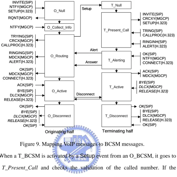
mapping is straightforward except for the slow-start version of H.323. Figure 9 depicts the mapping for H.323, SIP, and MGCP.
When a call request message arrives (e.g., INVITE for SIP, SETUP for H.323, or NOTIFY for MGCP) from a calling party, the corresponding O_BCSM becomes active and initialize itself to state O_Null. The O_BCSM proceeds to state O_Collect_Info where a called number or address is collected from the calling party. For SIP and H.323, the INVITE and SETUP messages carry the identifier of the called party, media descriptor, and signaling transport address. Hence the O_BCSM simply skips state O_Collect_Info and go to state O_Routing directly. For MGCP, however, a RQNT message should be sent to the calling party to collect the dialed number. Once the calling party collects the number dialed, it sends a NTFY with the dialed number to the O_BCSM. Then, the O_BCSM transits to state O_Routing.
State O_Routing responds to the calling party with the call progressing message (e.g., 100 Trying for SIP or CALLPROC for H.323). In addition, the VoIP protocol used by the called party is determined, and a Setup event is issued. Consequently, a T_BCSM for the called party is initialized at state T_Null to handle this Setup event. The O_BCSM stays in state O_Routing waiting for the Alert and Answer events sent from the T_BCSM. If both events are received, the call has been accepted by the called party and the O_BCSM responds with a call connect message (such as CONNECT for H.323, OK for SIP, or MDCX for MGCP) to the calling party indicating that the call has been accepted. The O_BCSM stays at state O_Active until the call is terminated.
O_Null O_Routing O_Disconnect T_Null T_Active T_Alerting T_Disconnect Setup Alert Answer Disconnect
Originating half Terminating half
O_Collect_Info T_Present_Call RQNT(MGCP) NTFY(MGCP) INVITE(SIP) NTFY(MGCP) SETUP(H.323) TRYING(SIP) CRCX(MGCP) CALLPROC(H.323) RINGING(SIP) MDCX(MGCP) ALERT(H.323) O_Active OK(SIP) MDCX(MGCP) CONNECT(H.323) ACK(SIP) INVITE(SIP) CRCXY(MGCP) SETUP(H.323) TRING(SIP) CALLPROC(H.323) RINGINH(SIP) ALERT(H.323) OK(SIP) NTFY(MGCP) CONNECT(H.323) ACK(SIP) MDCX(MGCP) BYE(SIP) DLCX(MGCP) RELEASE(H.323) OK(SIP) BYE(SIP) DLCX(MGCP) RELEASE(H.323) OK(SIP) BYE(SIP) DLCX(MGCP) RELEASE(H.323) OK(SIP) BYE(SIP) DLCX(MGCP) RELEASE(H.323) OK(SIP) O_Null O_Routing O_Disconnect T_Null T_Active T_Alerting T_Disconnect Setup Setup Alert Answer Disconnect
Originating half Terminating half
O_Collect_Info T_Present_Call RQNT(MGCP) NTFY(MGCP) INVITE(SIP) NTFY(MGCP) SETUP(H.323) TRYING(SIP) CRCX(MGCP) CALLPROC(H.323) RINGING(SIP) MDCX(MGCP) ALERT(H.323) O_Active OK(SIP) MDCX(MGCP) CONNECT(H.323) ACK(SIP) INVITE(SIP) CRCXY(MGCP) SETUP(H.323) TRING(SIP) CALLPROC(H.323) RINGINH(SIP) ALERT(H.323) OK(SIP) NTFY(MGCP) CONNECT(H.323) ACK(SIP) MDCX(MGCP) BYE(SIP) DLCX(MGCP) RELEASE(H.323) OK(SIP) BYE(SIP) DLCX(MGCP) RELEASE(H.323) OK(SIP) BYE(SIP) DLCX(MGCP) RELEASE(H.323) OK(SIP) BYE(SIP) DLCX(MGCP) RELEASE(H.323) OK(SIP)
Figure 9. Mapping VoIP messages to BCSM messages.
When a T_BCSM is activated by a Setup event from an O_BCSM, it goes to state T_Present_Call and checks the validation of the called number. If the number is valid, the T_BCSM sends a call request message (e.g., INVITE for SIP, SETUP for H.323, or CRCX for MGCP) to the called party and waits for the response messages such as trying, altering, and answered from the called party. Upon receiving the alerting message (e.g., 180 Ringing for SIP or ALERT for H.323), the T_BCSM informs the O_BCSM with an Alert event and proceeds to state T_Alert.
In state T_Alert, the T_BCSM waits for the call connect message (e.g., OK for SIP, CONNECT for H.323, or NTFY for MGCP). Once the message is received, the call has been accepted by the called party. The T_BCSM activates an Answer event to the O_BCSM and transits to state T_Active. In this state, an
acknowledgement message (e.g. ACK for SIP or MDCX for MGCP) is sent back to the called party. Thus far, a basic two party call connection is established.
If a disconnect message (e.g., BYE for SIP, RELEASE for H.323, or DLCX for MGCP) is received by either the originating or the terminating BCSM, the BCSM will issue a Disconnect event to the corresponding BCSM of this call. Both BCSMs proceeds to state Disconnect, and the call is terminated.
2.3.2 H.323 slow-start
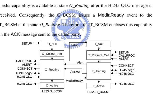
For the H.323 slow-start, the mapping is quite different and those events described above are inadequate to exchange the media capability. For the BCSMs described above, after the media capability of the calling party becomes available at state O_Null, the O_BCSM issues a Setup event. Moreover, after the capability of the called party becomes available at state T_Present_Call, the T_BCSM issues an Answer event respectively. However, for H.323 slow-start, this capabilities will not be determined until the H.245 negotiation after the CONNECT messages. As a result, the BCSMs do not get media capability when the Setup or Answer event is issued. In addition, there is no event reporting the media capability to the calling and called party after the Answer event. Thus, we made two modifications to the H.323 BCSMs. First, the Answer event is postponed to state T_Alert where the T_BCSM receives an H.245 open logical channel message (OLC) which carries the media capability for the called party. Second, a new event, media capability ready (MediaReady), is introduced at the end of state O_Routing to notify the T_BCSM the media capability of the calling party. Figure 10 shows the modifications to the mapping for the H.323 slow-start.
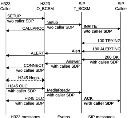
BCSMs of SIP and MGCP were modified to send a MediaReady event anyway at the end of state O_Routing. i.e., all O_BCSMs should issue a MediaReady event at state O_Routing. Although the called party of SIP or MGCP expects to receive the media capability when it receives the INVITE or the CRCX message, this capability exchange can be delayed till when the ACK or the MDCX message is received. Figure 11 shows the call flow of H323 and SIP interworking where the H.323 terminal is in slow-start mode. The call flow of a slow-start H323 terminal and an MGCP phone can be done in a similar manner. If the calling party is an H.323 phone using the slow-start feature, the T_BCSM issues an INVITE message without specifying the caller’s media capability to the SIP callee. The media capability is available at state O_Routing after the H.245 OLC message is received. Consequently, the O_BCSM issues a MediaReady event to the T_BCSM at the state O_Routing. Therefore, the T_BCSM encloses this capability in the ACK message sent to the called party.
O_Null O_Routing O_Active T_Null T_Active T_Alerting Setup Alert Answer H.323 O_BCSM H.323 T_BCSM O_Collect_Info T_Present_Call SETUP CALLPROC ALERT SETUP CALLPROC ALERT CONNECT CONNECT H.245 nego. H.245 nego. H.245 OLC H.245 OLC H.245 OLC H.245 OLC MediaReady O_Null O_Routing O_Active T_Null T_Active T_Alerting Setup Setup Alert Answer H.323 O_BCSM H.323 T_BCSM O_Collect_Info T_Present_Call SETUP CALLPROC ALERT SETUP CALLPROC ALERT CONNECT CONNECT H.245 nego. H.245 nego. H.245 OLC H.245 OLC H.245 OLC H.245 OLC MediaReady
H323 Caller H323 O_BCSM SIP T_BCSM SIP Callee SETUP w/o caller SDP
H323 messages Evetns SIP messages Setup w/o caller SDP CALLPROC INVITE w/o caller SDP 100 TRYING 180 ALERTING 200 OK with callee SDP Alert Answer with callee SDP CONNECT w/o callee SDP H245 Nego. H245 OLC
with caller SDP MediaReady with caller SDP H245 OLC with callee SDP ACK with caller SDP ALERT H323 Caller H323 O_BCSM SIP T_BCSM SIP Callee SETUP w/o caller SDP
H323 messages Evetns SIP messages Setup w/o caller SDP CALLPROC INVITE w/o caller SDP 100 TRYING 180 ALERTING 200 OK with callee SDP Alert Answer with callee SDP CONNECT w/o callee SDP H245 Nego. H245 OLC
with caller SDP MediaReady with caller SDP H245 OLC with callee SDP ACK with caller SDP ALERT
Figure 11. Call flow of H.323 (slow-start) and SIP interworking.
2.4 System Implementation and Result
To reduce the effort in developing a VoIP gateway, we use existing, well-developed protocol stacks and endpoints. In our implementation, we use the MGCP and SIP protocol stacks developed by CCL/ITRI, Taiwan and the open-source H.323 protocol stack developed by OpenH323. In addition, our experiment platform includes two residential gateways (RGWs) which are also developed by ITRI using D/41E and D/41ESC cards from Dialogic Corp. The RGWs support MGCP and can connect up to 16 telephones. The ICA platform also supports Microsoft NetMeeting (using H.323) and SIP user agent. The H.323 BCSMs are modified from the source code of the OpenH323's OpenGate that supports registration administration status (RAS) messages and gatekeeper-routed call signaling. We have also developed a SIP proxy/registrar based on the ITRI
SIP protocol stack. Figure 12 summarizes the components used in our platform. In our experiments, a call can be successfully set up between any two VoIP phones. The Microsoft NetMeeting currently supports only H.323 slow-start version; we use an open-source OpenPhone (with both slow-start and fast-start capabilities) to test the cases of slow-start version. In addition, a Vocal sip proxy, developed by Vovida, was used to test calls between SIP UAs. Since an ICA acts as both SIP proxy and H.323 gatekeeper, an ICA can initiate a call to the phones that are under the control of a SIP proxy or an H.323 gatekeeper without further modification.
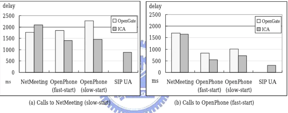
The comparison of the delays in establishing a call between various types of phones by OpenGate H.323 gateway, our ICA, and Vocal SIP proxy is depicted at Figure 13. No result of inter-protocol calls through OpenGate and Vocal is listed, because they do not convert the messages of different protocols. Figure 13.a shows call establishment delays for the calls initiated from various types of phones to NetMeeting, which only equipped with slow-start mode, and Figure 13.b shows those for calls to OpenPhone in H.323 fast-start Mode. Although our ICA supports signaling conversion for different VoIP protocols, the results indicates that the ICA sets up calls faster than the OpenGate in all cases except for calls between two NetMeeting users.
ITRI MGCP protocol Stack RGW Telephone Microsoft NetMeeting NCTU SIP Proxy ITRI SIP-UA OpenH323 ITRI SIP Protocol Stack
Opengate Gatekeeper NCTU ICA or OpenPhone ITRI MGCP protocol Stack RGW Telephone Microsoft NetMeeting NCTU SIP Proxy ITRI SIP-UA OpenH323 ITRI SIP Protocol Stack
Opengate Gatekeeper
NCTU ICA
or OpenPhone
Figure 12. Components used in our platform.
0 500 1000 1500 2000 2500 NetMeeting OpenPhone (fast-start) OpenPhone (slow-start) SIP UA ms OpenGate ICA delay 0 500 1000 1500 2000 2500 NetMeeting OpenPhone (fast-start) OpenPhone (slow-start) SIP UA ms OpenGate ICA delay
(a) Calls to NetMeeting (slow-start) (b) Calls to OpenPhone (fast-start) Figure 13. Call establishment delays.
2.5 Conclusions
We have presented a simple, flexible framework for the interworking functions of VoIP protocols based on IN half-call BCSM. In addition, we have implemented the basic gateway components, O_BCSMs and T_BCSMs, for SIP, H.323, and MGCP. Using these components, gateways for SIP/H.323, SIP/MGCP, and MGCP/H.323 can be constructed. This approach simplifies the effort in interworking with a call signaling protocol, such as ISUP and Q.931, in the
network. By using the same interaction events of the half-call model, the BCSMs of a call signaling protocol can interwork with the existing BCSMs. In addition, an ICA containing all the BCSMs is able to translate messages between call signaling protocols. Under this half-call control framework, a converged VoIP network can be managed by a group of coordinating ICAs such that two user devices managed by different ICAs can communicate. The call routing function that determines the location and protocol of the called party has not been fully investigated in this paper. As a mobile user may change his IP address and VoIP devices constantly, this problem becomes even more complicated. We need registration and/or paging schemes to track mobile users in the converged telecommunication network. Recently, P2P (peer-to-peer) VoIP communications, such as Skype, have become very popular. The interworking function for a P2P VoIP system and a client-server one (such as SIP) is an important issue that needs to be investigated.
Chapter 3
One-Pass GPRS and IMS Authentication
Procedure for UMTS
Universal Mobile Telecommunications System (UMTS) supports Internet protocol (IP) multimedia services through IP multimedia core network subsystem (IMS). Since the IMS information is delivered through the general packet radio service (GPRS) transport network, a UMTS mobile station (MS) must activate GPRS packet data protocol (PDP) context before it can register to the IMS network. In the Third-Generation Partnership Project (3GPP) specifications, authentication is performed at both the GPRS and the IMS networks before an MS can access the IMS services. We observe that many steps in this 3GPP “two-pass” authentication procedure are identical. Based on our observation, this chapter proposes a one-pass authentication procedure that only needs to perform GPRS authentication. At the IMS level, authentication is implicitly performed in IMS registration. Our approach may save up to 50% of the IMS registration/authentication traffic, as compared with the 3GPP two-pass procedure. We formally prove that the one-pass procedure correctly authenticate the IMS users.
Universal Mobile Telecommunications System (UMTS) proposed by the Third-Generation Partnership Project (3GPP) is a third-generation (3G) mobile telecommunications technology evolved from general packet radio service (GPRS) [20]. Fig. 3.1 illustrates the UMTS packet switched (PS) core network (CN), where the packet data services of a mobile station (MS) are provided by the serving GPRS support node (SGSN) via UMTS terrestrial radio access network (UTRAN). The SGSN connects to the external data network through the gateway GPRS support node (GGSN). Furthermore, the SGSN communicates with the home subscriber server (HSS) and the authentication center (AuC) to retrieve subscriber data and authentication information of an MS. The AuC, which may be collocated with the HSS, is responsible for security management of subscribers. UMTS supports voice and multimedia services through the PS CN based on the Internet Protocol (IP) technology. Specifically, the 3GPP defines IP multimedia core network subsystem (IMS) to support multimedia services such as voice telephony, video, real-time interactive games, messaging, and multimedia conferencing [21].In IMS, multimedia services are provided by call session control function (CSCF) utilizing session initiation protocol (SIP) [6],[22].Three types of CSCFs are defined in IMS: A proxy-CSCF (P-CSCF) located in the visited network of an MS is responsible for redirecting the SIP messages of an MS to the home network (where the HSS/AuC resides). A serving-CSCF (S-CSCF) is located in the home network of the MS to provide session control of multimedia services. The S-CSCF interacts with the application servers to obtain value added services. Furthermore, the S-CSCF communicates with the HSS and the AuC to receive IMS-related subscriber data and authentication information of the MS. An interrogating-CSCF (I-CSCF) is a firewall for the SIP messages toward the home network, and is responsible for selecting an S-CSCF for the MS.
Fig. 3.1. UMTS architecture for packet switched service domain.
In UMTS, when an MS sends an “Initial L3 message” (e.g., location update request, connection management service request, routing area update request, attach request, paging response, etc.) to the SGSN, the SGSN may be triggered to authenticate the user. The authenticating parties are HSS/AuC in the home network and the universal subscriber identity module (USIM) in the MS. GPRS authentication consists of two major procedures [19], [23].
• Distribution of authentication information from the AuC to the SGSN: The SGSN sends an authentication data request to the HSS/AuC with the parameter international mobile subscriber identity (IMSI) of the MS, and receives a response with an array of authentication vectors (AVs) from the AuC. An authentication vector consists of a random number RAND, an expected response
XRES,a cipher key CK, an integrity key IK, and an authentication token AUTN.
Each AV is good for one authentication and key agreement between the SGSN and the MS.
procedure performs authentication between an MS and the network by showing knowledge of a preshared secret key К that is only available in the USIM of the MS and the AuC. The SGSN invokes the authentication procedure with an authentication vector. This procedure supports mutual authentication between the MS and the network. Specifically, the AUTN is used by the MS to authenticate the network, and the RES/XRES pair is used by the SGSN to authenticate the MS (where the RES is generated by the MS). Details of the procedure will be given in Section II-A. The MS also computes two keys CK and IK using the received RAND and the preshared secret key К stored in the USIM. On the network side, the SGSN passes CK and IK to the UTRAN. During data transmission, CK and IK are used for ciphering and integrity between the MS and the UTRAN. Data ciphering and integrity is out of the scope of this chapter, and will not be discussed further.
In addition to GPRS authentication, it is necessary to authenticate the MS before it can access IMS services. Without IMS authentication, a mobile user who passes the GPRS authentication can easily fake being another IMS user. Details of the fake procedure will be elaborated in Section II-C. IMS authentication is performed between the IMS subscriber identity module (ISIM) in the MS and the AuC in the home network [24]. This procedure is basically the same as the GPRS authentication. In this procedure, the CSCF first sends a multimedia authentication request to the HSS/AuC with the IP multimedia private identity (IMPI) of the MS, and receives a response with an array of AVs. (This step is skipped if the CSCF already has the AV array.) The CSCF then invokes the IMS authentication and key agreement procedure with an authentication vector. The MS authenticates the network through the received
AUTN and the CSCF authenticates the MS using the RES/XRES pair. Detailed
message flow of this procedure will be given in Section II-B.
two “authentication passes” are duplicated. In other words, the two-pass authentication proposed in 3GPP 33.203 [24] is not efficient. In this chapter, we propose a one-pass authentication procedure that effectively combines both the GPRS and the IMS authentications. We prove that this simplified one-pass authentication procedure correctly authenticate the IMS users.
3.2 3GPP TWO-PASS AUTHENTICATION
This section describes the 3GPP two-pass authentication procedure. We first describe GPRS authentication in Section 3.2-A, and then we elaborate more on IMS authentication in Section 3.2-B. In Section 3.2-C, we explain why authentication must be performed in both the GPRS and the IMS levels.
A. GPRS Authentication
When an MS invokes the GPRS access (e.g., turns on its power), the MS sends an attach request to the SGSN. This message will trigger the GPRS authentication [20], which is implemented by GPRS mobility management (GMM) between the MS and the SGSN, and signaling system number 7 (SS7) mobile application part (MAP) between the SGSN and the HSS/AuC [25].This procedure consists of the following steps (see Fig. 3.2).
Step G.1) Consider an MS with the IMSI value imsi and the IMPI value impi. To access the GPRS services, the MS sends a GMM Attach Request (with the parameter IMSI = imsi) to the SGSN.
Step G.2) If the SGSN has the AVs of the MS, then Steps G.2 and G.3 are skipped. Otherwise, the SGSN must obtain the AV’s from the HSS/AuC. That is, the SGSN invokes the authentication vector distribution procedure by sending a MAP SEND AUTHENTICATION INFO Request message to the HSS/AuC (with the parameter IMSI = imsi ).
Step G.3) The HSS/AuC uses imsi to retrieve the record of the MS, and generates an ordered array of AVs (based on the preshared secret key К in the MS record). The generated AV array is sent to the SGSN through a MAP SEND AUTHENTICATION INFO Response message.
Step G.4) The SGSN selects the next unused authentication vector in the ordered AV array and sends the parameters RAND and AUTN (from the selected authentication vector) to the MS through a GMM Authentication and Ciphering Request message.
Step G.5) The MS checks whether the received AUTN can be accepted. If so, it produces a response RES that is sent back to the SGSN through a GMM
Authentication and Ciphering Response message. The SGSN compares the received RES with the XRES. If they match, then the authentication and key agreement exchange is successfully completed.
Step G.6) The SGSN sends a GMM Attach Accept message to the MS, and the attach procedure is completed.
After GPRS authentication, GPRS registration follows (details of GPRS registration can be found in [27]). Then, the MS performs packet data protocol (PDP) context activation to obtain access to the GPRS network. The PDP context specifies the application-layer packet data protocol and the routing information used for the GPRS communication session (see [28] for the details).