Contributed Paper
Motion Adaptive Interpolation with Horizontal Motion Detection
for Deinterlacing
Shyh-Feng Lin, Yu-Ling Chang, and Liang-Gee Chen, Fellow, IEEE
Abstract —
A motion adaptive deinterlacing algorithm ispresented in this paper. It consists of the ELA-Median directional interpolation, same-parity 4-field horizontal motion detection, morphological operation for noise reduction and adaptive threshold adjusting. The edges can be sharper when the ELA-Median directional interpolation is adopted. The same-parity 4-field horizontal motion detection detects faster motion and makes more accurate determinations about where objects are going to move. The morphological operation for noise reduction and adaptive threshold adjusting preserve the actual texture of the original objects. The proposed method achieves cost-efficient hardware implementation with low complexity, low memory usage, and high-speed processing capability. In addition, it consumes less time in producing high-quality images and allows the audience to enjoy a high-quality TV sequence on their progressive devices. The experimental results show that the proposed algorithm is more cost-effective than previous systems.
Index Terms — Deinterlacing, ELA-Median, Morphological, Progressive.
I. INTRODUCTION
Deinterlacing is an important process which converts ordinary TV sequences into progressive sequences for the sake of displaying on progressive devices (e.g. Computers, Plasma Display, and Projection TV). Some defects such as edge flicker, jagged effects, blur, and line-crawling will cause uncomfortable visual artifacts, if deinterlacing is not done perfectly.
Two low-complexity deinterlacing methods are BOB[1] and Weave[1], which are commonly adopted in the software approach. BOB is an intra-interpolation method, which uses a single field to reconstruct one progressive frame. However, the vertical resolution is halved and the image is blurred. Weave is a simple deinterlacing method combining directly two interlaced fields into one progressive frame. However, the line-crawling effect will occur in the motion area.
1Some motion adaptive techniques [9]-[13] [15]- [24] have
been presented to improve image quality. Sugiyama and Nakamura [9] proposed a method of motion-compensated adaptive interpolation. They used motion-estimation and
1This work was supported in part by the AVermadia Inc., R.O.C. under Grant No. 90-S-B59.
Shyh-Feng Lin, Yu-Ling Chang, and Liang-Gee Chen are with the National Taiwan University, Department of Electrical Engineering and Graduate Institute of Electronics Engineering, Taipei 106, Taiwan, R.O.C. (e-mail: [email protected], [email protected],
adaptive interpolation to reconstruct the missing field with the information obtained from the backward and the forward fields. Hilman [10] and Haan [20] proposed a motion-compensated frame-rate conversion algorithm with interpolation to reduce the 3:2 pull-down artifacts. Ville [11] proposed a motion adaptive technique on a fuzzy motion detector. Schutten and de Haan [21] proposed an object-based true-motion estimation algorithm to eliminate the 2-3 pull-down sequences. Sun [23] proposed a shortest path technique of the motion information to re-align the fields of a video image. Patti [24] proposed using global motion estimation to reconstruct the video for solving the panning or zooming situation. All of these methods can provide better deinterlacing quality. However, these methods demand a lot of computational power and are very expensive for consumer electronic products.
In this paper, a motion adaptive deinterlacing method with Edge Line Average (ELA), 4-field horizontal motion detection in same parity, noise reduction, and threshold adjusting is proposed. The overview of intra-field and inter-field deinterlacing will be discussed in Section 2. The fundamentals of the proposed method will be described in Section 3. Section 4 shows the experimental results and comparison with previous methods. Section 5 gives the conclusion and remarks.
II. DEINTERLACING OVERVIEW
Fundamentally, deinterlacing could be characterized into four categories: intra-field deinterlacing, inter-field deinterlacing, motion adaptive deinterlacing, and motion-compensated deinterlacing.
A. Intra-Field Deinterlacing
The most cost-efficient method is intra-field deinterlacing by the same field. It is widely used in software implementations, because it needs less computational power and only one delay line buffer. The most common method of the intra-field deinterlacing is line doubling, which is used in small LCD panels. However, the jagged effect will occur in the oblique line and flicker will be seen in the texture of the detail. Some methods of interpolation use upper and lower line pixels to reduce such flickers and alias.
ELA is the most popular algorithm in this category. It is a kind of directional edge interpolation [5]. Three pixels in the previous scan line and the next scan line are referenced to determine the obvious edge in the image as shown in Fig. 1. This method can eliminate the blurring effect of the bilinear interpolation and gives sharp/straight edges.
Although intra-field interpolation is very cost-efficient and needs one line buffer only, the resolution of the picture is half
of the original. In addition, some defects may occur when an object only exists in the same-parity field.
n
n+1
n+2
n-2
n-1
k-1
k+1
original
scan line
original
scan line
New line
Fig. 1. Edge directional interpolation
B. Inter-Field Deinterlacing
Inter-field interpolation means merging two fields into one frame, so it needs one-field buffer. The video quality is better than that of intra-field interpolation in static area, but the line-crawling effect, as shown in Fig. 2, will occur in the motion area.
Fig. 2. Line-crawling effect occurs when merged directly.
C. Motion Adaptive Deinterlacing
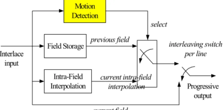
The motion adaptive deinterlacing combines the advantages of both intra-field deinterlacing and inter-field deinterlacing. It detects the motion areas first, and then adopts intra-field deinterlacing in motion areas and inter-field deinterlacing in static areas. The block diagram is shown in Fig. 3. High-resolution and flicker-free picture can be realized in both static area and motion area. The image quality is the same as that of intra-field interpolation. Motion adaptive deinterlacing relies on accurate motion detection. Any erroneous detection will cause artifacts as spots in the video.
Motion Detection Field Storage Intra-Field Interpolation interleaving switch per line Progressive output Interlace input previous field select current field current intra-field interpolation
Fig. 3. Block diagram of motion adaptive deinterlacing.
Current Field Reference Field
Frame
Separated into 2 field
Fig. 4. Block matching by motion estimation method.
D. Motion-Compensated Method
The motion-compensated method utilizes motion estimation to find the most similar blocks in the neighboring fields and calculates its motion vectors, as shown in Fig. 4. Then a new field is reconstructed from neighboring field. Block matching needs a large buffer size to locate the current macroblock and reference macroblock. Additionally, it also needs a lot of computational power to calculate the Sum of Absolute Difference (SAD) value. Although motion-compensated methods have greater potential to produce better result, they are also more complex since they require a motion estimation engine.
In the next section, the fundamental of proposed deinterlacing is described. This new deinterlacing scheme using pixel-based motion detection is very cost-effective. It contains the noise reduction engine and can get reliable motion information to achieve high image quality.
III. PROPOSED MOTION-ADAPTIVE DEINTERLACING
The block diagram of the proposed method is shown in Fig. 5. Three-field buffers are used to store the reference data. The enhanced ELA module does the directional edge interpolation according to the current-field information. The same-parity 4-field horizontal motion detection calculates the difference between the forward-forward field and the current field, and the difference between the forward field and the backward field. After the morphological operation for noise reduction, the field difference will be sent to the threshold-adjusting module. According to the pixel value of the current field, the
threshold-adjusting module will provide an adaptive threshold value to produce the motion information. The decision block receives the motion information, and then selects the forward field in the static area and the output of ELA in the motion area. Finally, the current field and the interpolation field are merged into the progressive frame.
Field storage Field storage Field storage 4-field horizontal motion detection & 3:2 pull-down detection Enhanced ELA
Progressive frame out Field in Forward Field Current Field Backward Field Forward-Forward Field Forward Field
Current Field Current Field by ELA
Decision Block Interpolation Field Morphological operation Threshold adjusting Current Field
M otion Inform ation
Interleave by line
Current Field
Fig. 5. Block diagram of proposed deinterlacing method.
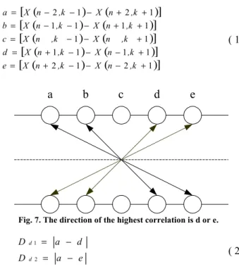
A. Enhanced Directional Interpolation - with Median ELA The directional interpolation algorithm using ELA [5] can generate straight and high contrast image. However, some artifacts will occur due to erroneous detection in a non-dominant directional edge region. The modified ELA [6] can eliminate the artifacts by interpolating the missing pixel according to the classification of the edge region. First, five differences are calculated along the five directions as shown in Fig. 6 and ( 1 ).
n
n+1
n+2
n-2
n-1
k-1
k+1
original
scan line
original
scan line
New line
X
Y
minmum difference
a
b
c
d
e
Fig. 6. ELA with median processing.
The minimum difference is chosen to be the highest correctional edge, and the opposite direction of the highest correction is used to detect a non-dominant directional edge region. As shown in Fig. 7, if the highest correction is a, then d and e are used for detecting the dominant edge region. The
differences of directional difference are calculated as Dd1, Dd2
as shown in ( 2 ).
(
)
(
)
[
]
(
)
(
)
[
]
(
)
(
)
[
]
(
)
(
)
[
]
(
)
(
)
[
2 1 2 1]
1 1 1 1 1 1 1 1 1 1 1 2 1 2 + − − − + = + − − − + = + − − = + + − − − = + + − − − = ,k n X ,k n X e ,k n X ,k n X d n ,k X n ,k X c ,k n X ,k n X b ,k n X ,k n X a ( 1 )c
d
e
a
b
Fig. 7. The direction of the highest correlation is d or e.
e a D d a D d d − = − = 2 1 ( 2 )
Td is the threshold value determined empirically. If Dd1> Td and Dd2 > Td, the region is dominant directional edge, a directional interpolation will perform along the edge. At last, the median of three pixels ( 3 ) - the produced pixel, the corresponding pixels in the previous line and in the next line- is calculated to prevent the occurrence of bursting pixels. For a non-dominant edge region, a bilinear interpolation was performed along the vertical region. The flowchart of enhanced ELA is shown in Fig. 8.
(
) (
)
[
X nk X nk ELA]
MedianY= , −1, , +1, ( 3 )
Two scan lines
Difference of edge directional calculation (a,b,c,d,e) Dominant edge Vertical bilinear interpolation Directional interpolation Median filter No Yes
B. 4-Field Motion Detection in Same Parity 1) Same-Parity Field Detection
For interlaced video, the vertical position of the even field and the odd field is slightly different. Same-parity field [25] detection detects the motion area by the even-field-to-even-field or odd-even-field-to-even-field-to-odd-even-field-to-even-field difference. The benefits can be seen in the static area. Using successive-field difference for motion detection will lead to some problems. For example, the static letter “T” in the progressive frame can be separated into two fields as shown in Fig. 9. The motion detection by successive-field difference will determine the horizontal edge of the letter T to be different. The wrong decision will cause the static letter T in motion and produce the flicker line in the horizontal edge. With same-parity field detection, the even-to-even-field difference and odd-to-odd-field difference will be the same. The correct decision can be made and the static letter T can be reconstructed perfectly.
C. 4-Field Horizontal Motion Detection
The 2-field difference [14] will lead to a wrong decision, if the object is moving too fast. As shown in Fig. 10, a person is moving very fast between the forward field and the backward field, crossing the current-field position. Both the forward field and backward field are background at the position of the person in the current field. So the 2-field difference between the forward field and backward field is very small and the person is detected to be static. The line-crawling effect will occur to this erroneous detection.
y
t
Even field
t-2 Odd fieldt-1 Even fieldt Odd fieldt+1
different different sam e sam e successive-field difference same-parity-field difference xdifferent Progressive frame
Fig. 9. 4-field motion detection in same parity.
Same-parity 4-field motion detection involves two more fields than 2-field motion detection, as shown in Fig. 11; the
current field and the forward-forward field. It also has same-parity field detection ability, which can solve the detection error caused by the different positions in the even field and odd field. The extra field difference between the current field and forward-forward field can detect more motion information than same-parity 2-field motion detection. So the line-crawling effect can be eliminated by this method.
Current Field Backward Field
Field Difference Forward Field
Progressive Out
Fig. 10. The 2-field motion detection.
Current Field Forward Field
Forward-Forward Field Backward Field
Field Difference Field Difference OR Progressive Out
Fig. 11. The 4-field motion detection.
a b c d e Forward Backward & FForward Current
Forward (c) Forward (b) Forward (d) Forward (a) Forward (e)
Backward Direction c is minimum Direction b is minimum Direction d is minimum Direction a is minimum Direction e is minimum Forward
Fig. 12. 4-field horizontal motion detection.
Usually, adaptive motion deinterlacing will adopt intra-field interpolation for pan sequences, resulting in lower resolution.
Five-directional temporal interpolation is added into the same-parity 4-field motion detection to achieve resolution as high as inter-field interpolation as shown in Fig. 12. Block matching is done between the forward field and the backward field by 1×3 blocking size. If the minimum difference of block matching is smaller than the threshold, and the pixel difference between the forward-forward field and the current field is also smaller than the threshold, the temporal prediction will be adopted. The proposed same-parity 4-field horizontal motion detection can eliminate the detection error due to vertical position of interlaced sequence and fast motion, and can achieve high-resolution result to process the pan sequences.
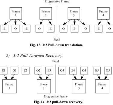
D. 3:2 Pull-Down Detection 1) 3:2 Pull-Down algorithm
The 3:2 pull-down method means transforming the sequence rate from 24 frames/second into 60 fields/second. An example is shown in Fig. 13, frame 1 is separated into three fields; even field/ odd field/ even field. The first even field and the third even field of frame 1 are the same. Frame 2 is separated into two fields as described above. So two frames will be translated into five fields, which means the original 24 frames/second will be translated into 60 fields/second.
E O E O E O E O E O Progressive Frame Field Frame 1 Frame 2 Frame 3 Frame 4
Fig. 13. 3:2 Pull-down translation.
2) 3:2 Pull-Downed Recovery E1 O1 E2 O2 E3 O3 E4 O4 E5 O5 Frame 1 Progressive Frame Field Frame 2 Frame 3 Frame 4
Fig. 14. 3:2 pull-down recovery.
Same-parity field detection, which means detection from even-to-even field or from odd-to-odd field, can also detect the 3:2 pull-downed sequences. If the same-parity field detection detects that two fields resemble each other periodically, then the 3:2 pull-down sequence is detected. The redundancy of an even field or an odd field will be removed. As shown in the Fig. 14, E1 and O1 are merged into Frame 1, and E2 is discarded. O2 and E3 are merged into Frame 2. E4 and O4 are merged into Frame 3, and O3 is discarded. E5 and O5 are merged into Frame 4. So five fields will be translated into two frames, which means 60 fields/second will be translated into
24 frames/second. Then the progressive frame will be reconstructed perfectly. The circuits of same-parity field detection can be used both in the 3:2 pull-down detection and 4-field motion detection, saving the hardware cost and meeting low-power consideration.
E. Morphological Operation for Noise Reduction
Video signal after coding and transmission will involve some noise, which will cause erroneous motion detection. The morphological operation scheme will eliminate the noise of field difference to preserve the reliable motion information. Morphological operation, which includes the erosion process and dilation process, can reduce the high-frequency noise of field difference. The purpose of erosion is to reduce the high-frequency noise, and its equation is shown in ( 4 ). The 3×3 window is shown in Fig. 15, if one of the nine pixels is black, then the center pixel is black. After the erosion process, we go through a dilation process. The purpose of dilation is extending the motion area, because the erosion process will erode the edge of the motion area. If one of the nine pixels in the 3×3 window is white, then the center pixel is white.
F(j+1,k-1) F(j,k-1) F(j-1,k-1) F(j+1,k) F(j,k) F(j-1,k) F(j+1,k+1) F(j,k+1) F(j-1,k+1)
Fig. 15. The 3××××3 window of morphological operation.
1)] k 1, F(j 1), k , F(j 1), k 1, F(j ), k 1, F(j ), k , F(j ), k 1, F(j 1), -k 1, F(j 1), -k , F(j 1), -k 1, -MIN[F(j k) G(j, + + + + + + = ( 4 ) G(j,k) is the mask result of each pixel after erosion. F(j,k) is the original same-parity field difference. The 3×3 dilation of gray scale difference is defined as ( 5 ).
1)] k 1, G(j 1), k G(j, 1), k 1, -G(j ), k 1, G(j ), k G(j, ), k 1, -G(j 1), -k 1, G(j 1), -k G(j, 1), -k 1, -MAX[G(j k) D(j, + + + + + + = ( 5 ) Here, D (j, k) is the final mask result after dilation and erosion. G (j, k) is the mask result after erosion. We can easily discover in Fig. 16 (a) that the original-field difference (shown in Fig. 16 (b)) contains a lot of noise and we may not know where the real motion areas are. Black represents the static area, and white represents the motion area. The difference after “erosion” is shown in Fig. 16 (c), where there is a great improvement in noise reduction. But we lose the difference information on the edge of the objects. So the dilation process is utilized after applying the erosion process and obtains a
“thicker” edge (Fig. 16 (d)) by which we can determine the motion areas more correctly.
(a)
(c)
(b)
(d)
Fig. 16. (a) The original field, (b) The original-field difference, (c) The field difference after erosion, (d) Noise reduction after morphological reduction.
F. Threshold Adjusting
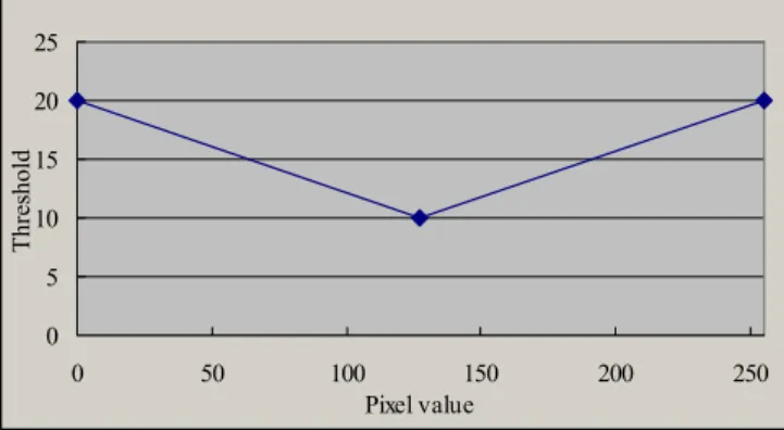
The threshold value is used to determine the motion area. We detect the motion area when the field difference is larger than the threshold value. When the field difference is smaller than the threshold value, the static area is found. Human eyes are less sensitive to lighter or darker area than gray area, so the threshold at those pixels should be much smaller than the threshold at gray color pixels, just like Fig. 17. Equation ( 6 ) presents the simple threshold adjusting mechanism for the proposed motion detection. For an 8bit gray scale picture, 255 and 0 mean the white and black color, respectively. Experimental result shows that when the current pixel value is 255 or 0, which is not sensitive for human eyes, the threshold value is 20. When the current pixel value is 127, which has high sensitivity, the threshold value is 10, as shown in Fig. 18.
255 128 while ) 255 ( 128 10 20 128 e whil 128 10 20 < < − − = < − = Y Y Threshold Y Y Threshold ( 6 ) Lum inance 10 Threshold 20 20 255 0
Fig. 17. The sensitivity of the luminance influences the threshold of motion detection. 0 5 10 15 20 25 0 50 100 150 200 250 Pixel value Threshold
Fig. 18. Pixel value vs. threshold.
IV. EXPERIMENTAL RESULTS AND ANALYSIS
This section discusses the implementation issues and experimental results of the proposed deinterlacing methods.
A. Analysis of Hardware Cost
Now, we address the comparisons on memory access, local buffer size, and instruction counts. The “n” in Table I means the pixel numbers to be processed.
Due to the pipelined architecture, the bilinear interpolation should read one pixel into local buffer while processing each pixel. The ELA process needs to examine two pixels on two different scanlines. The memory access frequency of the motion-compensated method may vary in different architectures, but it is at last 10 times larger than the bilinear method. Our proposed method reads five pixels from memory each time when the same-parity 4-field horizontal motion detection is utilized. The instruction counts are profiled by I-prof with gcc 3.0.2 and the target video sequence is for CIF 30FPS. There is much to optimize in the C codes for hardware implementation. But it is shown that the proposed method needs only 1.2GIPS for real-time deinterlacing. The instruction count of the proposed method is similar to those of the intra-field deinterlacing methods and is much smaller than the motion-compensated methods.
It is obvious that motion-compensated deinterlacing is the most complex and time-consuming method, while the proposed algorithm possesses less complexity and memory access frequency than the motion-compensated deinterlacing, and has the same complexity as intra-field deinterlacing.
TABLEI
MEMORY ACCESS, BUFFER SIZE, AND INSTRUCTION COUNTS
COMPARISON External Memory Access Read Write Buffer Size [bytes] Instruction Counts [MIPS] Bilinear n n 1 481 ELA 2n n 10 879 Motion-compensated >10n n 528 30,248 Proposed 5n n 25 1,224
B. Comparisons of Subject View
(a)
(c)
(b)
(d)
Fig. 19. (a) Original even field, (b) Original odd field, (c) The letter K disappears by intra-field interpolation in the even field, (d) The letter O disappears by intra-field interpolation in the odd field.
Fig. 20. (a) Line-crawling effect occurs when merged directly, (b) Line-crawling effect is introduced by same-parity 2-field detection, (c)
Jagged effect caused by bilinear interpolation, (d) Straight line by ELA processing, (e) Results obtained by the proposed deinterlacing method.
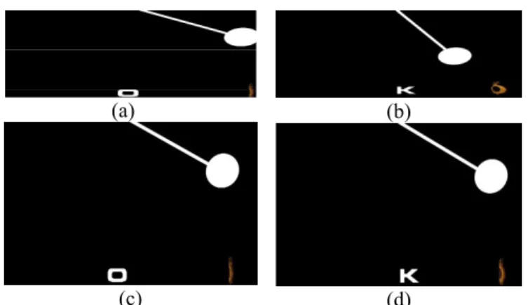
The sequence “Pendulum” emphasizes on texture preservation and edge sharpness when deinterlacing is done. The original sequence, as shown in Fig. 19 (a) (b), can be divided into three parts. The most important of all is the oscillating pendulum: it swings back and forth between the left and the right of the screen. In the combined frame, the line-crawling effect appears at the motion area of the pendulum. The second part is the title “OK”, which is composed of an “O” exiting only in the even fields and a “K” exiting only in the odd fields. The third part of the sequence is the logo rotating at the lower-right-hand corner of the screen. The rotating logo is like a non-rigid body, and the real appearance of non-rigid bodies are often lost in motion-compensated deinterlacing while the motion adaptive deinterlacing can reconstruct the non-rigid bodies very well. The original two fields and the directly combined frame are shown in Fig. 19 (a), (b), and Fig. 20 (a), respectively.
Edge in the picture can be recognized when intra-field deinterlacing is adopted. But the words “O” and “K” will disappear alternatively because they exist only in different parity fields, as shown in Fig. 19 (c) and Fig. 19 (d), respectively.
The resulting picture of the two-field same-parity motion detection [6] is shown in Fig. 20 (b). Although the words “OK” are successfully preserved, the line-crawling effect still exists in the shaft of the pendulum.
For intra-field deinterlacing, bilinear interpolation and ELA show different sharpness. The result of bilinear interpolation is shown in Fig. 20 (c), where alias edges can be seen. The result of the ELA is shown in Fig. 20 (d), we can see that the edge is much sharper and straighter than that achieved by bilinear interpolation.
The result of the proposed method, which has same-parity 4-field horizontal motion detection and enhanced ELA, is shown as in Fig. 20 (e). The edges of the pendulum and the logo are sharp and very straight, and the letters “O” and “K” can be displayed correctly in the even field and odd field, respectively. The proposed method has overcome the problems of all other deinterlacing methods.
Deinterlacing PSNR 352 x 288p 60 Frames/sec
¡ õ
2
Compare 352 x 288i 60 fields/sec 352 x 288p 60 Frames/sec Fig. 21. Performance measurement method.The performance of the PSNR comparisons of deinterlacing achieved by using the sequence converted from progressive sequences is shown in Fig. 21. The original 60 (a)
(c)
(e)
(b)
frames/second progressive frame is decimated into 60 fields/second interlaced fields. After deinterlacing, the 60 fields/second interlaced fields are reconstructed into 60 frames/second progressive frames. Then we compare the original progressive sequence and the output of deinterlacing.
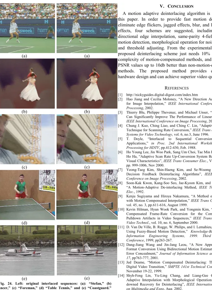
From TABLE II and Fig. 22, the proposed 4-field motion detection method has better performance than the bilinear, ELA, and 2-field motion detection methods. The three sequences of Mobile, Stefan and Dancer have large motion, so the proposed method adopted intra-interpolation in most areas. Others are better than previous methods, even up to 10db. The original interlace sequences are shown in the left of Fig. 23 and Fig. 24, and the progressive results of the sequence obtained by the proposed method are shown in the right of Fig. 23 and Fig. 24.
TABLE II PSNR COMPARISON
Name Merged Bilinear ELA 2-Field 4-Field
Silent 29.52 29.15 26.72 37.86 39.82 Weather 31.01 26.93 25.55 37.96 40.49 Mobile 17.83 24.92 23.99 26.20 25.83 Mother Daughter 33.59 32.89 30.82 37.76 42.65 Container 31.01 28.14 25.04 40.27 37.81 Stefan 11.86 26.91 25.49 24.90 26.12 Dancer 23.19 36.15 33.41 31.94 34.06 Foreman 23.30 29.96 27.41 30.44 33.21 Hall Monitor 30.61 30.68 27.75 35.34 39.14 Table Tennis 23.89 27.32 25.85 31.55 35.11 Coastguard 22.59 27.84 26.32 29.32 30.45 (a) (b) (c) (d) (e) (a) (b) (c) (d) (e)
Fig. 23. Left: original interlaced sequences: (a): “Silent,” (b): “Weather,” (c): “Mobile,” (d): “Mother and Daughter,” and (e): “Container.” Right: progressive results obtained by the proposed method. 0 5 10 15 20 25 30 35 40 45 Silent WeatherMobile Mother Daughter
ContainerStefanDancerForeman
Hall MonitorTable TennisCoastguard
PSNR Merged Bilinear ELA 2-Field 4-Field
(a) (b) (c) (d) (e) (a) (b) (c) (d) (e)
Fig. 24. Left: original interlaced sequences: (a): “Stefan,” (b) “Dancer,” (c) “Foreman,” (d) “Table Tennis,” and (e) “Coastguard.” Right: progressive results obtained by the proposed method.
V. CONCLUSION
A motion adaptive deinterlacing algorithm is presented in this paper. In order to provide fast motion detection and eliminate edge flickers, jagged effects, blur, and line-crawling effects, four schemes are suggested, including enhanced directional edge interpolation, same-parity 4-field horizontal motion detection, morphological operation for noise reduction, and threshold adjusting. From the experimental results, the proposed deinterlacing scheme just needs 10% of hardware complexity of motion-compensated methods, and can achieve PSNR values up to 10db better than non-motion-compensated methods. The proposed method provides cost-efficient hardware design and can achieve superior video quality.
REFERENCES [1] http://nickyguides.digital-digest.com/index.htm
[2] Hao Jiang and Cecilia Moloney, “A New Direction Adaptive Scheme for Image Interpolation,” IEEE International Conference on Image
Processing, 2002.
[3] Thierry Blu, Philippe Thevenaz, and Michael Unser, “How A Simple Can Significantly Improve The Performance of Linear Interpolation,”
IEEE International Conference on Image Processing, 2002.
[4] Chung J. Kuo, Ching Liao, and Ching C. Lin, “Adaptive Interpolation Technique for Scanning Rate Conversion,” IEEE Trans on Circuits and
Systems for Video Technology, vol. 6, no.3, June 1996.
[5] T. Doyle, “Interlaced to Sequential Conversion for EDTV Applications,” in Proc. 2nd International Workshop Signal on
Processing for HDTV, pp.412-430, Feb. 1988.
[6] Ho Young Lee, Jin Woo Park, Sang Um Choi, Tae Min Bae, and Yeong Ho Ha, “Adaptive Scan Rate Up-Conversion System Based on Human Visual Characteristics”, IEEE Trans Consumer Elec., Vol. 46, Issue: 4, pp. 999-1006, Nov 2000.
[7] Yeong-Taeg Kim, Shin-Haeng Kim, and Se-Woomg Park, “Motion Decision Feedback Deinterlacing Algorithms”, IEEE International
Conference on Image Processing, 2002.
[8] Soon-Kak Kwon, Kang-Soo Seo, Jae-Kyoon Kim, and Yung-Gil Kim, “A Motion-Adaptive De-interlacing Method, IEEE Trans Consumer
Elec., 1992.
[9] Kenju Sugiyama and Hiroya Nakamura, “A Method of Deinterlacing with Motion Compensated Interpolation,” IEEE Trans Consumer Elec., vol. 45, no. 3, pp.611-616, August 1999.
[10] Kevin Hilman, Hyun Wook Park, and Yongmin Kim, “Using Motion-Compensated Frame-Rate Conversion for the Correction of 3:2 Pulldown Artifacts in Video Sequences,” IEEE Trans. Circuits Syst.
Video Technol., vol. 10, no. 6, September 2000.
[11] D. Van De Ville, B. Rogge, W. Philips, and I. Lemahieu, “Deinterlacing Using Fuzzy-Based Motion Detection,” Knowledge-Based Intelligent
Information Engineering Systems, 1999. Third International Conference, 1999, pp263-267.
[12] Dang-Jiang Wang and Jin-Jang Leou, “A New Approach to Video Format Conversion Using Bidirectional Motion Estimation and Hybrid Error Concealment,” Journal of Information Science and Engineering
17, pp763-777, 2001.
[13] Jed Deame, “Motion Compensated Deinterlacing: The Key to the Digital Video Transition,” SMPTE 141st Technical Conference in NY, November 19-22, 1999.
[14] Shyh-Feng Lin, Yu-Ling Chang, and Liang-Gee Chen, “Motion Adaptive Interpolation with Morphological Operation and 3:2 Pull-downed Recovery for Deinterlacing”, IEEE International Conference
on Multimedia and Expo, Aug. 2002.
[15] Dongil Han, Chang-Yong Shin, Seung-Jong Choi, and Jong-Seok Park, "A Motion Adaptive 3-D De-interlacing Algorithm Based on The Brightness Profile Pattern Difference ", IEEE Transactions on
[16] C. Ryu, S.P. Kim,"Deinterlacing Using Motion Compensated Local Spectra", Conference Record of the Twenty-Ninth Asilomar Conference
on,Signals, Systems and Computers, vol. 2, pp 1394 -1397, 1996.
[17] J. Kovacevic, R.J. Safranek, E.M. Yeh, "Deinterlacing by Successive Approximation", IEEE Transactions on Image Processing, vol. 6, Issue: 2, pp 339 -344, Feb. 1997.
[18] D. Van de Ville, W. Philips, and I. Lemahieu, "Motion Compensated De-interlacing for Both Real Time Video and Still Images",
International Conference on Image Processing, vol. 2, pp 680 -683,
2000.
[19] G. De Haan, E.B. Bellers, "Deinterlacing-an Overview", Proceedings of
the IEEE, vol. 86, Issue: 9, pp 1839 -1857, Sept. 1998.
[20] G. de Haan, E.B. Bellers, "De-interlacing of Video Data ", IEEE
Transactions on Consumer Electronics, Vol.43 Issue: 3, pp. 819 -825,
Aug. 1997.
[21] R.J. Schutten, G. de Haan, “Real-time 2-3 Pull-down Elimination Applying Motion Estimation/Compensation in a Programmable Device”, IEEE Transactions on Consumer Electronics, Vol. 44 Issue: 3, pp. 930 –938, Aug. 1998.
[22] B. Martins, S. Forchhammer, “A Unified Approach to Restoration, Deinterlacing and Resolution Enhancement in Decoding MPEG-2 Video”, IEEE Transactions on Circuits and Systems for Video
Technology, Vol. 12 Issue. 9, pp. 803 –811, Sept. 2002.
[23] Changming Sun , “De-interlacing of Video Images Using a Shortest Path Technique”, IEEE Transactions on Consumer Electronics, Vol. 47 Issue: 2 , pp. 225 –230, May 2001.
[24] A.J Patti, M.I Sezan and A.M Tekalp, “Robust Methods for High Quality Stills from Interlaced Video in the Presence of Dominant Motion,” IEEE Transactions on Circuits and Systems for Video
Technology, Vol. 7, No. 2, pp. 328-342, Apr. 1997.
[25] You-Young Jung, Byung-Tae Choi, Yung-Jun Park, and Sung-Jea Ko, “An Effective De-interlacing Technique Using Motion Compensated Interpolation”, IEEE Transactions on Consumer Electronics, Vol. 46 Issue: 3, pp. 460 –466, Aug. 2000.
Shyh-Feng Lin was born in I-Lan, Taiwan, R.O.C., in 1974. He received the B.S. degree from the Department of Electrical Engineering, Tatung Institute of Technology, Taipei, Taiwan, R.O.C., in 1996. He received the M.S. degree from the Department of Electrical Engineering, National Taiwan University, Taipei, Taiwan, R.O.C., in 1998. He currently is working toward the Ph.D. degree at the Department of Electrical Engineering, National Taiwan University.
He joined AVermedia Inc., Taiwan, R.O.C., in 2001. His research interests include video coding technology, video processing, digital TV, and associated VLSI architectures.
Yu-Ling Chang was born in Taipei, Taiwan, R.O.C., in 1981. He received the B.S. degree from the Department of Electrical Engineering, National Taiwan University, Taipei, Taiwan, R.O.C., in 2002. He currently is working toward the Master degree at the Graduate Institute of Electrical Engineering, National Taiwan University.
His research interests include video coding technology, digital TV, and associated VLSI architectures.
Liang-Gee Chen (F’01) was born in Yun-Lin, Taiwan, R.O.C., in 1956. He received the B.S., M.S., and Ph.D. degrees in electrical engineering from National Cheng Kung University, Tainan, Taiwan, R.O.C., in 1979, 1981, and 1986, respectively.
He was an Instructor (1981–1986) and an Asso-ciate Professor (1986–1988) in the the Department of Electrical Engineering, National Cheng Kung University. In the military service during 1987–1988, he was an Associate Professor in the Institute of Re-source Management, Defense Management College. In 1988, he joined the Department of Electrical Engineering, National Taiwan University, Taiwan, R.O.C. During 1993–1994, he was a Visiting Consultant in the DSP Research Department, AT&T Bell LabS, Murray Hill, NJ. In 1997, he was a Visiting Scholar of the Department of Electrical Engineering, University of Washington at Seattle. Currently, he is a Professor at National Taiwan University. His current research interests are DSP architecture design, video processor design, and video coding system.
Dr. Chen has served as Associate Editor of IEEE TRANSACTIONS ON CIRCUITS AND SYSTEMS FOR VIDEO TECHNOLOGY since 1996, Associate Editor of IEEE TRANSACTIONS ON VLSI SYSTEMS since January 1999, and Associate Editor of the IEEE TRANSACTIONS ON CIRCUITS AND SYSTEMS II: ANALOG AND DIGITAL SIGNAL PROCESSING. He was the Associate Editor of the Journal of Circuits, Systems and Signal Processing in 1999, served as the Guest Editor of The Journal of VLSI Signal Processing-Systems for Signal, Image and Video Technology, and was the General Chairman of the 7th VLSI Design/CAD Symposium and the 1999 IEEE Workshop on Signal Processing Systems: Design and Implementation. He received the Best Paper Award from the ROC Computer Society in 1990 and 1994, the Long-Term (Acer) Paper Awards annually from 1991 to 1999, the Best Paper Award of the Asia-Pacific Conference on Circuits and Systems in the VLSI design track in 1992, the Annual Paper Award of Chinese Engineer Society in 1993, and the Outstanding Research Award from the National Science Council and the Dragon Excellence Award frome Acer, both in 1996. He is currently the elected IEEE Circuits and Systems Distinguished Lecturer for 2001–2002. He is a member of Phi Tan Phi.