J.-S. Wu
1 Assistant Professor, e-mail: chongsin@cc.nctu.edu.twK.-C. Tseng
Graduate Student Department of Mechanical Engineering, National Chiao-Tung University, 1001 Ta-Hsueh Road, Hsinchu 30050, TaiwanParallel Particle Simulation of the
Near-Continuum Hypersonic
Flows Over Compression Ramps
This paper describes the analysis of the near-continuum hypersonic flow over a compres-sion ramp using the two-dimencompres-sional parallel direct simulation Monte Carlo (DSMC) method. Unstructured and triangular solution-based adaptive mesh depending on the local mean free path is used to improve the resolution of solution for the flow field with highly varying properties. In addition, a freestream parameter is defined to help reduced the cell numbers in the freestream area, resulting in appreciable decrease of the compu-tational time (20–30%) without sacrificing the accuracy of the solution. The two-step multilevel graph partition technique is used for physical domain decomposition, employ-ing estimated particle number distribution in each cell as the graph vertex weight. 32 IBM-SP2 processors are used throughout the study unless otherwise specified. The Effect of the outflow vacuum boundary condition, compression ramp angle, freestream condi-tion, and length of the ramp to the flow field are investigated. Computational results are compared with previous numerical results whenever available.关DOI: 10.1115/1.1523068兴
Introduction
Due to the complicated physical features possessed by hyper-sonic compression ramp flow and its importance to the design of hypersonic vehicles, it has been studied extensively in the past, 关1–6兴. Details of the general physics can be found in Refs. 关1–6兴 and references cited therein. Several points, however, are worthy of mentioning here. First, the tip flows are in strong nonequilib-rium and hence continuum assumption breaks down in this re-gime, where the Navier-Stokes equation fails to approximate the flow features. Second, most flows relevant to hypersonic vehicles are in the range of transition to near-continuum, thus the direct simulation Monte Carlo method 共DSMC兲, 关7兴, is well-suited to study this complicated flow field, although the computational cost is extremely high in the near-continuum regime. Third, the flow possesses very complicated physical features involving highly varying flow properties, which are very difficult to resolve using nonadaptive mesh.
In order to well resolve the complicated flow features of a com-pression ramp using the DSMC method, two issues are required to handle it properly. First, the distribution of computational cells should be adapted to the variation of the flow properties. Hence, solution-based adaptive mesh is generally required. In traditional computational fluid dynamics 共CFD兲, unstructured mesh rather than structured mesh is more flexible for the purpose of mesh adaptation. The same applies to the DSMC method. There were, however, relatively few studies developed along this line,关8,9兴, in the DSMC community. Robinson关8兴 first applied the re-meshing technique to adapt the unstructured mesh, then Wu et al.关9兴 ap-plied the mesh-embedding scheme instead to adapt the unstruc-tured mesh. Second, due to the high computational cost of the DSMC simulation, especially in the near-continuum regime, par-allel processing is highly expected. Fortunately, DSMC is readily paralleled using domain decomposition due to its particle nature and high locality due to assumed binary collisions. Detailed reviews of parallel processing of DSMC can be found in Refs. 关8,10兴, which will not be repeated here for brevity.
As mentioned earlier, the hypersonic flow over a compression ramp involves rather complicated flow phenomena with highly varying flow properties. Hence, integration of parallel processing and unstructured adaptive mesh is highly expected to accelerate the computational speed to an acceptable level as well as to im-prove the resolution.
Therefore, the specific objectives of the current study are 1. to integrate the previously developed DSMC method using
unstructured adaptive mesh, 关9兴, and the parallel DSMC method,关10兴, using unstructured mesh;
2. to apply this method to compute a hypersonic compression ramp flow and compare the results with those of Moss et al. 关6兴; and
3. to study the effects of ramp angles, free-stream conditions, outflow vacuum boundary conditions, and ramp length on the flow properties, including pressure, shear stress, and heat transfer coefficients.
The paper begins with descriptions of numerical methods. Re-sults of short compression are compared to those of Moss et al. 关6兴 and different effects on surface properties are discussed in turn.
Numerical Method and Procedures
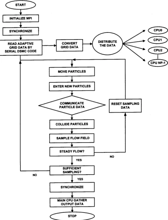
Parallel Direct Simulation Monte Carlo „DSMC… Method. The DSMC algorithm is readily parallelized through the physical domain decomposition as mentioned previously. The cells of the computational grid are distributed among the processors. Each processor executes the DSMC algorithm in serial for all particles and cells in its own domain. Parallel communication occurs when particles cross the domain 共processor兲 boundaries and then par-ticle data are transferred between processors. Figure 1 shows a simplified flow chart of the parallel DSMC method proposed in the current study. Note that CPUs are numbered from 0 to np-1 in the figure.
In this method, an approach of handling the cell related data is proposed. An unstructured triangular mesh is first constructed us-ing the advancus-ing front method by a commercial code, Hyper-Mesh™,关11兴. Then, a preprocessor 共or ‘‘converter’’兲 is designed to convert the unstructured mesh data into the globally sequential but locally unstructured mesh data for each processor in confor-1To whom correspondence should be addressed.
Contributed by the Fluids Engineering Division for publication in the JOURNAL OFFLUIDSENGINEERING. Manuscript received by the Fluids Engineering Division Jan. 2, 2002; revised manuscript received Aug. 20, 2002. Associate Editor: Y. Mat-sumoto.
mation with the partitioning information from graph partitioner 共e.g., JOSTLE 关12兴兲, as schematically presented in Fig. 2. In each processor, the cell numbering is unordered共unstructured兲, but the starting共and ending兲 cell number increases sequentially with the processor number. We term this as ‘‘globally sequential but locally unstructured.’’ Thus, in each processor the memory is only needed to record the starting and ending cell numbers. This simple con-version dramatically reduces the memory cost otherwise required for storing the mapping between the local cell number in each processor and the global cell number in the computational domain if unstructured cells are used,关10兴. The resulting mesh data is then imported into the parallel DSMC code.
After reading the mesh data on a master processor共cpu 0兲, the mesh data are then distributed to all other processors according to the designated domain decomposition. All the particles in each processor then start to move as in sequential DSMC algorithm.
The particle related data are sent to a buffer and are numbered sequentially when hitting the inter-processor boundary共IPB兲 dur-ing its journey within a simulation time-step. After all the particles in a processor are moved, the destination processor for each par-ticle in the buffer is identified via a simple arithmetic computa-tion, owing to the previously mentioned approach for cell num-bering, and the transferred data are then packed into arrays. Considering communication efficiency, the packed arrays are sent as a whole to its surrounding processors, in turn based on the tagged numbers recorded earlier. Once a processor sends out all the packed arrays, it waits to receive the packed arrays from its surrounding processors in turn. This ‘‘send’’ and ‘‘receive’’ opera-tion serves practically as a synchronizaopera-tion step during each simu-lation time-step. Received particle data are then unpacked and each particle continues to finish its journey for the remaining
time-step. The above procedures are repeated twice since there might be some particles crossing the IPB twice during a simula-tion time-step.
After all particles on each processors have come to their final destinations at the end of a time-step, the program then carries out the indexing of all particles and the collisions of particles in each
computational cell in each processor as usual in a sequential DSMC code. The particles in each cell are then sampled at the appropriate time as specified.
The current parallel code, in SPMD 共single program multiple data兲 paradigm, is implemented on the IBM-SP2 machines 共dis-tributed memory system兲 using the message passing interface 共MPI兲 to exchange information between processors. It is thus es-sentially no code modification required to adapt to other parallel machines共e.g., IBM-SMP, PC-clusters兲 with a similar distributed memory system once they use the same MPI libraries for data communication.
The DSMC Method With Mesh Adaptation. All mesh ad-aptation methods need some means to detect the requirement of local mesh refinement to better resolve the features in the flow fields and hence to achieve more accurate numerical solutions. This also applies to DSMC. It is important for the adaptation parameters to detect a variety of flow features but does not cost too much computationally. Often the gradient of the properties, such as pressure, density, or velocity, is used as the adaptation parameter to detect rapid changes of the flow-field solution in traditional CFD. However, by considering the statistical nature of
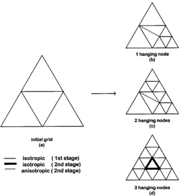
Fig. 3 Mesh refinement scheme for unstructured triangular mesh
Fig. 4 Sketch of the two-dimensional hypersonic compression corner flow
the DSMC method, density is adopted instead as the adaptation parameter in the current study. Using density as the adaptation parameter in DSMC is justified since it is generally required that the cell size be much smaller than the local mean free path to better resolve the flow features as advocated by Bird关7兴. To use the density as an adaptation parameter, a local cell Knudsen num-ber is defined as
Knc⫽ c
冑
Ac, (1)
wherecis the local cell mean free path based on VHS model and Ac is the magnitude of the local cell area. When the mesh
adap-tation module is initiated, the local Knudsen number at each cell is computed and compared with a preset value, Kncc. If this value is
less than the preset value, then mesh refinement is required. If not, check the next cell until all cells are checked. This adaptation parameter is expected to be most stringent on mesh refinement 共more cells are added兲; hence, the impact to the DSMC computa-tional cost might be high, but it is required to obtain an accurate solution.
Considering the practical applications of mesh adaptation in external flows, we have added another constraint,⭓0, in
ad-dition to the constraint of the local cell Knudsen number. Note that the freestream parameter,, is defined as
⫽
⬁, (2)
where0 is a preset value. Not only does the above constraint
helps to reduce the total refined cell numbers to an acceptable level by reducing the cell numbers in the freestream region a great deal, but it also reduces the total computational time up to 30%.
Two general rules of mesh adaptation are described as follows: 共1兲 Isotropic mesh refinement is employed for those cells which flag for mesh refinement. A new node is added on each edge共face兲 of a parent cell and connecting them to form four child cells. In general, this will create one to three hanging nodes in the nonre-fined interfacial cell, which is next to the isotropically renonre-fined cell. Existence of hanging node共s兲 not only complicates the particle
movement, but also increases the cost of the cell-by-cell particle tracing due to the increase of face numbers. Hence, a remedy is proposed as follows in item共2兲.
共2兲 Anisotropic mesh refinement is utilized in the (interfacial) cells next to those cells have just been isotropically refined. Tri-angular child cells are formed no matter how many hanging nodes exist. Typical methods of interfacial mesh refinement in the trian-gular cells are schematically shown in Fig. 3.
The mesh adaptation procedures are performed using a serial DSMC code using very few particles共⬍1%兲. As a rule of thumb, about 10,000 particles sampled in a cell are considered enough for the mesh adaptation purpose. The mesh adaptation module is ini-tiated and checks through all the cells to determine if mesh en-richment is required based on the specific adaptation parameter, which was explained previously. If mesh enrichment is conducted, associated neighbor identifying arrays are updated or created, co-ordinates and number of faces for new cells are recorded, and sampled data on the coarse parent cell are redistributed共based on the magnitude of cell area兲 to the finer child cells accordingly. The above procedures are repeated until the prescribed maximum number of adaptation levels has been reached or no mesh enrich-ment is required for all the cells in the computational domain. Finally the adaptive mesh due to the above procedures is output-ted as the computational cells for further parallel DSMC process-ing. In summary, output adaptive mesh and density distribution is then used as the information for domain decomposition using the graph partitioner, JOSTLE,关12兴. Finally, the previously developed parallel DSMC code,关10兴, is then utilized for computation. Results and Discussion
Figure 4 illustrates the sketch of a hypersonic flow over a com-pression ramp as previously simulated by Moss et al.关6兴. Current flow conditions are summarized in Table 1, where cases 1– 4 (xc ⫽71.4 mm, xr⫽31.55 mm) corresponds to those simulated in
Moss et al. 关6兴 except for case 5 (xc⫽71.4 mm, xr⫽71.4 mm)
with a longer ramp. For completeness, they are briefly described here as follows: VHS nitrogen gas, freestream Mach number
M⬁⫽18.9⬃24.3, freestream density ⬁⫽5.14E-5
⬃39.12E-5 Kg/m3
, freestream temperature T⬁⫽8.3⬃15.6 K, and a fully thermally accommodated and diffusive flat and ramp wall
Fig. 5 Unstructured adaptive mesh for case 5„xrÄ71.4 mm, Ä25 deg… „163,658 cells, 3 levels of mesh adaptation…
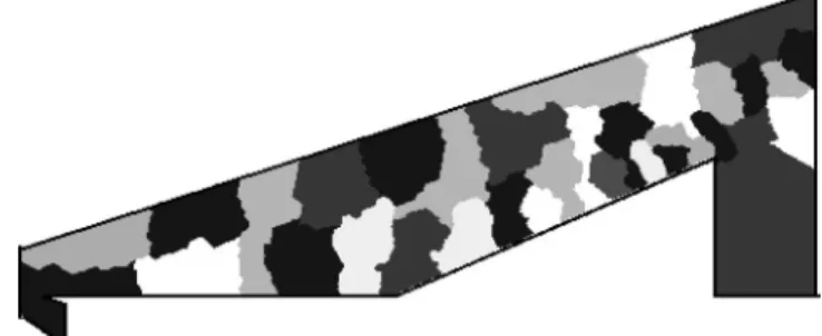
Fig. 6 Multilevel graph partition for case 5 „xrÄ71.4 mm, Ä25 deg… „32 CPUs…
Table 1 Flow conditions of simulation
xc⫽71.4 mm Case xr 共mm兲 ⬁x10 ⫺5 (Kg/m3兲 共m/s兲V⬁ 共K兲T⬁ 共K兲Tw M共–兲⬁ 共mm兲⬁ Kn共–兲⬁ Re共–兲⬁ 1 31.55 5.14 1340 8.3 383 22.8 0.475 0.0066 3938.66 2 31.55 10.72 1452 8.6 394 24.3 0.230 0.0032 8670.23 3 31.55 18.09 1448 14.1 340 18.9 0.154 0.0022 10120.06 4 31.55 39.12 1740 15.6 341 21.6 0.073 0.0010 24402.49 5 71.4 39.12 1740 15.6 341 21.6 0.073 0.0010 24402.49
with Tw⫽340⬃394 K. The resulting Knudsen numbers and
Rey-nolds numbers based on xcare in the range of 0.0010–0.0066 and
3938.66 –24402.49, respectively. Temperature-dependent rota-tional energy exchange model of Parker关7兴 is used to model the diatomic nitrogen gas. Vibration energy transfer is neglected due to the low temperature involved. Typical particle numbers and cell numbers are in the range of 0.8 – 8 million and 19,000–250,000, respectively, depending upon the rarefaction of the problem. Ad-ditionally,0 is normally set to 1.03 unless otherwise specified.
Typical adaptive mesh distribution is shown in Fig. 5 for the case 5 at ramp angle of 25 deg共163,658 cells兲. Corresponding distri-bution for domain decomposition using the graph-partitioning technique is illustrated in Fig. 6. Note that the size of each sub-domain is obviously different due to the variations of estimated
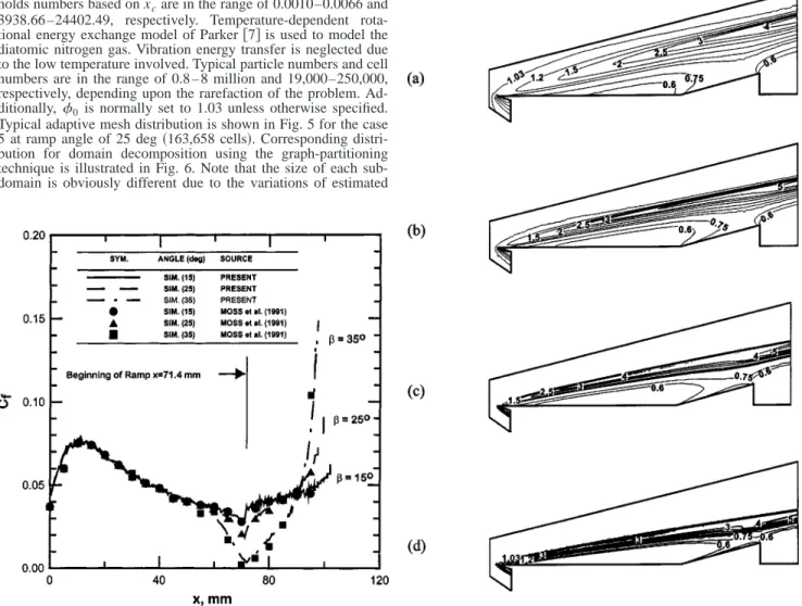
Fig. 7 Pressure coefficient distribution along the solid wall for
Ä15 deg, 25 deg, and 35 deg„case 1, KnⴥÄ0.0066…
Fig. 8 Shear stress coefficient distribution along the solid wall forÄ15 deg, 25 deg, and 35 deg„case 1, KnⴥÄ0.0066…
Fig. 9 Heat transfer coefficient distribution along the solid wall forÄ15 deg, 25 deg, and 35 deg„case 1, KnⴥÄ0.0066…
Fig. 10 Density contours at different freestream Knudsen number for Ä15 deg „a… KnⴥÄ0.0066; „b… KnⴥÄ0.0032; „c…
density distribution 共or equivalently computational load兲 in the computational domain. Note that 32 IBM-SP2 processors are used throughout the current study unless otherwise specified.
Verification of the Present Implementation. In Moss et al. 关6兴, the outflow vacuum condition was placed right at the end of the ramp instead of the current position as shown in Fig. 4. It was, however, problematic since previous results showed a large circu-lation bubble formed at the compression corner for a large ramp angle with the flow reattached near the end of the ramp. This might cause subsonic outflow共or even reversed flow兲 near the end of the ramp wall, which renders the vacuum outflow conditions unphysical. In the current study, we have moved the outflow vacuum boundary condition further downstream to the wake re-gion as shown in Fig. 4, which coincides more with the experi-mental conditions,关6兴.
Figures 7, 8, and 9 illustrate the pressure, shear stress, and heat transfer coefficient distribution, respectively, along the solid wall for case 1共the most rarefied case in Table I with a short ramp兲 at three different ramp angles共15 deg, 25 deg, and 35 deg兲. Detailed discussion on the physics of the flow field is relatively brief since it can be found in Moss et al.关6兴. As shown in Fig. 7, the pressure distribution generally increases with the distance from the leading edge, reaches a maximum value 0.077 at approximately the posi-tion of x⫽20 mm, and then decreases to some value before the ramp corner, depending upon the ramp angle. Pressure increases
appreciably starting from the corner region due to the existence of ramp, especially for the 35 deg case. For the cases considered, the data generally coincide very well with those of Moss et al. 关6兴 except at the end of the ramp for the 35 deg case, due to the position of outflow vacuum condition. Current prediction shows that strong expansion occurs in this regime for the 35 deg case, which will be shown later. This is reasonable since the flow close to the end of the ramp wall is slowed down most due to the large angle of the ramp corner although no reverse flows occur. The placement of the outflow vacuum boundary condition in Ref.关6兴 will prevent the flow from expanding at this regime. In addition, shear stress and heat transfer coefficient distributions for all three ramp angles 共Fig. 8兲 along the solid wall agree reasonably well with those of Moss et al.关6兴. The current cell numbers for this case is on the order of 20,000, which is larger than that used by Moss et al.关6兴 共⬇7,000兲. But the distribution of cells is definitely better due to the solution-based adaptive mesh. Also the particle numbers is about 0.8 –2 million that is much larger than that 共⬇0.1–0.2 million兲 used in Ref. 关6兴. This represents that the cur-rent parallel DSMC simulation using unstructured adaptive mesh is at least as accurate as共or may be more accurate than兲 previous simulation study for the most rarefied case.
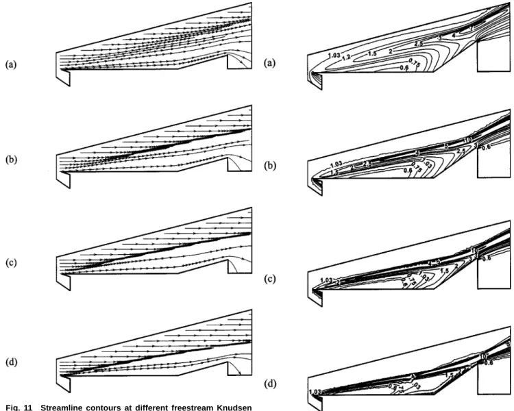
Fig. 11 Streamline contours at different freestream Knudsen number for Ä15 deg„a… KnⴥÄ0.0066; „b… KnⴥÄ0.0032; „c…
KnⴥÄ0.0022;„d…KnⴥÄ0.0010 Fig. 12 Density contours at different freestream Knudsen number for Ä35 deg „a… KnⴥÄ0.0066; „b… KnⴥÄ0.0032; „c…
Effects of Freestream Rarefaction and Ramp Angle. Ef-fects of rarefaction for the short ramp can be clearly demonstrated in Figs. 10, 11共15 deg兲 and Figs. 12, 13 共35 deg兲. In Figs. 11共a兲– 11共d兲 共⫽15 deg, density distribution兲, the density gradient across the leading-edge shock increases with decreasing freestream rar-efaction. In addition, rarefied region above the flat-plate increases with decreasing freestream rarefaction as well. In addition, strong gas expansion occurs at the end of the ramp wall, which causes the pressure to decrease as shown earlier in Fig. 7. Because of the short ramp length considered, the oblique shock due to compres-sion corner is not very clearly formed even in the case of the densest flow共Fig. 11共d兲兲. No separation bubble can be identified for all the cases considered with ramp angle of 15 deg 共Figs. 11共a兲–11共d兲, streamline contour兲. From Figs. 11共b兲–11共d兲, the leading-edge shock extends over the ramp due to the very blur 共weak兲 oblique shock. Additionally, the strength of the leading-edge shock increases with decreasing rarefaction as expected.
In Figs. 12共a兲–12共d兲 共⫽35 deg, density distribution兲, physical trend for density distribution is similar to those of 15 deg as shown in Fig. 10. There is, however, one distinct feature caused by the large ramp angle. Density in the corner region is more uniform than that of 15 deg case as compared with Figs. 10共a兲– 10共d兲. This is caused by the circulation bubble formed in the
com-pression corner as shown in Figs. 13共a兲–13共d兲 for lower freestream rarefaction cases. In addition, the gas expansion at the end of the ramp wall is more obvious as compared with that of the 15 deg case, which is expected due to the adverse pressure gradi-ent along the ramp caused by the large ramp angle. From both Figs. 12 and 13, the leading-edge shock is deflected upwards and mingled with oblique shock共due to the corner兲 at the end of the ramp due to the large ramp angle. Note that the oblique shock due to the ramp corner is not very clear because of the short ramp. In addition, the size of the separation bubble increases with decreas-ing rarefaction. The separation bubble even extends over 1/3 up-stream of the flat-plate length and almost covers the entire ramp
Fig. 13 Streamline contours at different freestream Knudsen number for Ä35 deg „a… KnⴥÄ0.0066; „b… KnⴥÄ0.0032; „c…
KnⴥÄ0.0022;„d…KnⴥÄ0.0010
Fig. 14 Pressure coefficient distribution along the solid wall forÄ15 deg, 25 deg, and 35 deg„case 4, KnⴥÄ0.0010…
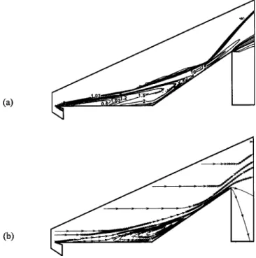
Fig. 15 Density and streamline contours at Ä35 deg „long ramp, case 5, KnⴥÄ0.0010…
wall. This definitely will dramatically change the surface proper-ties as can be seen, for example, in Fig. 14, where the pressure coefficient is much higher in the corner region for the⫽35 deg case as compared with the other two cases共⫽15 deg and 25 deg兲.
Generally speaking, the strength of leading-edge shock, gas ex-pansion at the end of the ramp, as well as the separation bubbles size in the corner increases with decreasing rarefaction.
Effects of Length of the Ramp. Effects of the ramp length on the flow structure can be illustrated in Fig. 15, where Kn⬁ ⫽0.001 共case 5, xr⫽71.4 mm,⫽35 deg兲 which is in the
near-continuum regime. The formation of the strong oblique shock is very clear at the later portion of the ramp due to the longer ramp considered. For the short ramp case at the same angle共Fig. 12共d兲兲, the oblique shock is comparably blurred due to the short ramp. In addition, the gas expansion fan the corner of the ramp共to the wake region兲 is clearly seen because of the formation of the strong oblique shock. A well-known neck region is clearly formed along the ramp wall. Comparing Fig. 15共b兲 and Fig. 13共d兲, we can see that the circulation bubble is larger because of the long ramp. Hence, the rarefied region above the flat-plate共as compared with the freestream value兲 becomes smaller due to the large circulation bubble. The nature of the interaction among the leading-edge shock, the viscous boundary layer along the solid wall and the oblique shock is rather complicated. The related discussion can be found in Robinson关8兴 and are skipped here.
Conclusions
A two-dimensional parallel DSMC method using unstructured solution-based adaptive mesh has been developed. Simulated data of a hypersonic flow over a compression ramp at a most rarefied condition are used to compare with previous reported results. It is then applied to simulate similar flow to study the effects of the freestream rarefaction, ramp angle, and the effects of the ramp length. This study shows that simulation of near-continuum flow using the DSMC method is possible using parallel processing. Future work considering dynamic load balancing during simula-tion for parallel DSMC is in progress and will be reported elsewhere.
Acknowledgment
This investigation was supported by the National Science Council of Taiwan, Grant No. NSC 90-2212-E-009-046. The au-thors also would like to express their sincere thanks to the com-puting resources provided by the National Center for High-Speed Computing of National Science Council of Taiwan.
Nomenclature
a⬁ ⫽ freestream sound speed
Cw ⫽ shear stress coefficient, 2w/⬁V⬁ 2
Cp ⫽ pressure coefficient, 2pw/⬁V⬁2 Ch ⫽ heat transfer coefficient, 2qw/⬁V⬁3
Kn⬁ ⫽ freestream Knudsen number, ⬁/xc M⬁ ⫽ freestream Mach number, U⬁/a⬁
p ⫽ pressure q ⫽ heat transfer rate
Re⬁,x ⫽ local Reynolds number,⬁V⬁x/⬁ T ⫽ temperature
Ttr ⫽ translational temperature U⬁ ⫽ freestream velocity
xc ⫽ distance from leading edge to the ramp corner xr ⫽ ramp length
 ⫽ ramp angle
⬁ ⫽ mean-free path in freestream ⫽ viscosity
⫽ density ⫽ shear stress Subscripts
c ⫽ corner
ref ⫽ reference condition
w ⫽ wall
⬁ ⫽ free-stream condition References
关1兴 Anderson, J. D., Jr., 1989, Hypersonic and High Temperature Gas Dynamics, McGraw-Hill, New York.
关2兴 Pullin, D. I., and Harvey, J. H., 1976, ‘‘A Numerical Simulation of the Rarefied Hypersonic Flat Plate Problem,’’ J. Fluid Mech., 78, pp. 689–707. 关3兴 Vogenitz, F. W., Broadwell, J. E., and Bird, G. A., 1969, ‘‘Leading Edge Flow
by the Monte Carlo Direct Simulation Technique,’’ 7th Aerospace Science Meeting, AIAA Paper No. 69–141.
关4兴 Chun, C.-H., 1991, ‘‘Experiments on Separation at a Compression Corner in Rarefied Hypersonic Flow,’’ Rarefied Gas Dynamics, A. Beylich, ed., VCH Publishers, New York, pp. 562–569.
关5兴 Moss, J., Rault, N., and Price, J. M., 1994, ‘‘Direct Monte Carlo Simulations of Hypersonic Viscous Interactions Including Separation,’’ Rarefied Gas
Dy-namics: Space Science and Engineering, B. D. Shzgal and D. P. Weave, eds.,
Washington, DC.
关6兴 Moss, J. N., Price, J. M., and Chun, C. H., 1991, ‘‘Hypersonic Rarefied Flow About a Compression Corner—DSMC Simulation and Experiment,’’ 26th Thermophysics Conference, AIAA Paper No. 91-1313.
关7兴 Bird, G. A., 1994, Molecular Gas Dynamics and the Direct Simulation of Gas
Flows, Oxford University Press, New York.
关8兴 Robinson, C. D., 1998, ‘‘Particle Simulation on Parallel Computers With Dy-namic Load Balancing,’’ Ph.D. thesis, Imperial College of Science, Technol-ogy and Medicine, U.K.
关9兴 Wu, J.-S., Tseng, K.-C., and Kuo, C.-H., 2001, ‘‘The Direct Simulation Monte Carlo Method Using Unstructured Adaptive Mesh and Its Application,’’ Int. J. Numer. Methods Fluids, accepted for publication.
关10兴 Wu, J.-S., Tseng, K.-C., and Yang, T.-J., 2001, ‘‘Parallel Implementation of the Direct Simulation Monte Carlo Method Using Unstructured Mesh and Its Ap-plication,’’ Int. J. Numer. Methods Heat Fluid Flow, submitted for publication. 关11兴 Hypermesh, Version 2.0, Altair Computing, Altair Engineering, Inc.,
Maple-lawn, MI.
关12兴 Walshaw, C., Cross, M., Everett, M. G., Johnson, S., and McManus, K., 1995, ‘‘Partitioning and Mapping of Unstructured Meshes to Parallel Machine To-pologies,’’ Proc. Irregular Parallel Algorithms for Irregularly Structured
Problems, A. Ferreia and J. Rolim, eds., 980, LNCS, Springer, Berlin, pp.