A MRMDF FFT Processor for MIMO OFDM
Applications
Yu-Wei Lin, Wan-Chun Liao, and Chen-Yi Lee
Department of Electronics Engineering & Institute of ElectronicsNational Chiao-Tung University 1001 Ta Hsueh Rd, Hsinchu, R.O.C
ywlin@si2lab.org
Abstract—in this paper, the proposed pipelined FFT processor, which is based on MRMDF structure, can deal with the simultaneous multiple input sequences more efficiently for MIMO OFDM applications. Furthermore, the hardware costs of memory and complex multipliers in our method can be saved by means of delay feedback and data scheduling approaches. The higher-radix FFT algorithm is also realized in our processor to reduce the number of complex multiplications. A test chip for 802.11n system has been designed using 0.13µm 1P8M CMOS process with core area of
2142 660× µm2. Power dissipation is 5.2mW when 128 points
FFT with four data streams are calculated. I. INTRODUCTION
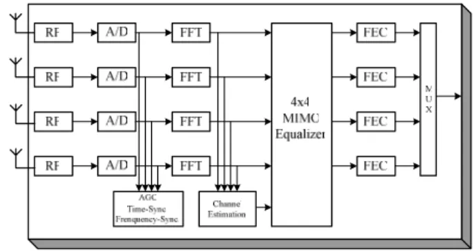
The combination of multiple-input and multiple-out (MIMO) signal processing with orthogonal frequency division multiplexing (OFDM) is considered as a promising solution for enhancing the data rates of next generation wireless communications systems operating in frequency-selective fading environments. The IEEE 802.11n standard established by High Throughput Task group based on MIMO OFDM system is to provide very high data throughput, offering data rate in excess of 600 Mb/s. A block diagram of the physical layer of IEEE 802.11n receiver is shown in Fig. 1. It can provide data rates from 6 M to 630 Mb/s. The bandwidth of the transmitted signal is 20 MHz with 64 subcarriers and 40 MHz with 128 subcarriers. The number of spatial streams (no. of the antennas) is from one to four. The OFDM symbol duration in the standard is 4 µs including 0.8 µs for a guard interval. Thus, the FFT/IFFT processor needs to deal with 64 or 128 points in 4 µs with 1~4 simultaneous input sequences, depending on the number of spatial streams. The multiple input sequences of 64/128-point FFT/IFFT processor need to be supported in IEEE 802.11n standard. In our view, the pipelined architecture should be the best choice for high-throughput rate applications since it can provide high throughput rate with acceptable hardware cost. In general, there are two types in the pipelined FFT architecture. One is Multi-Path Delay Commutator (MDC) and the other is Single-Path Delay Feedback (SDF) [1]. The MDC scheme can achieve higher throughput rate, while the SDF scheme
needs less memory and hardware cost. To our knowledge, so far, few papers have reported how to deal with multiple different input sequences simultaneously based on the pipelined FFT architecture for MIMO OFDM applications. The main purpose of this paper is to design a novel 4-data-path pipelined FFT architecture which is called Mixed-Radix Multi-Path Delay Feedback (MRMDF), by combining the features of the SDF and MDC architectures. The proposed FFT/IFFT processor can not only support 64/128 points but also deal with the different number of the input sequences from one to four for IEEE 802.11n applications. The approach will be described in more detail below.
Fig. 1 Block diagram of the physical layer of an IEEE 802.11n receiver.
II. ALGORITHM
Given a sequence x n( ) , an N-point Discrete Fourier
Transform (DFT) is defined as 0 (2 / ) ( ) ( ) 0...127, cos(2 / ) sin(2 / ), N kn N n nk j nk N N X k x n W k W e π πnk N j πnk N = − = = = = −
∑
(1)where x n( ) and ( )X k are complex numbers. In general,
higher-radix FFT algorithm has less number of complex multiplications compared with radix-2 FFT algorithm which is the simplest form in all FFT algorithms. In an example for 128-point FFT, the number of nontrivial complex multiplications of radix-8 FFT algorithm is 152, which is only 59.3% of that of radix-2 FFT algorithm [1]. So, we
9-3
225 0-7803-9162-4/05/$20.00 ©2005 IEEE
choose the radix-8 FFT algorithm to save the number of complex multiplications. Because 128-point FFT is not a power of 8, the mixed-radix FFT algorithm, including radix-2 and radix-8 FFT, is needed. First let
{
{
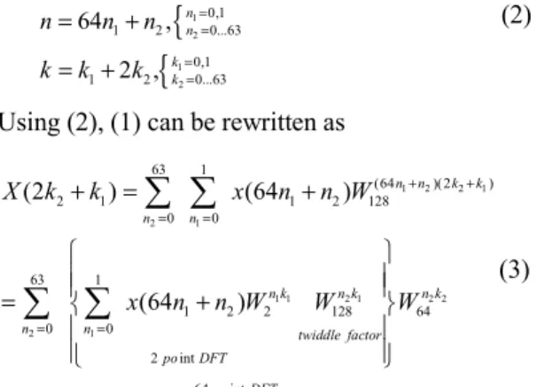
1 2 1 2 0,1 1 2 0...63 0,1 1 2 0...63 128 64 , 2 , n n k k N n n n k k k = = = = = = + = + (2)Using (2), (1) can be rewritten as
1 2 2 1 2 1 1 1 2 1 2 2 2 1 63 1 (64 )(2 ) 2 1 1 2 128 0 0 63 1 1 2 2 128 64 0 0 2 int 64 int (2 ) (64 ) (64 ) n n k k n n n k n k n k n n twiddle factor po DFT po DFT X k k x n n W x n n W W W + + = = = = + = + = +
∑ ∑
∑ ∑
(3)Equation (3) can be considered as a two-dimensional DFT. One is 64-point and the other is 2-point. Then we can complete the 128-point mixed-radix FFT algorithm by further decomposing the 64-point DFT with radix-23 FFT algorithm [1] .
The IFFT can be performed efficiently by taking the complex conjugate of input data and output data of the FFT without changing any coefficients in the original FFT algorithm so that the hardware implementation can be more efficient [3].
III. ARCHITECTURE
Block diagram of the proposed 64/128-point FFT/IFFT processor derived from (3) is depicted in Fig. 2. The features of the proposed FFT architecture are: multiple input sequence of 64/128 point can be supported in our proposed schemes; minimum memory capacity is required by using the delay feedback approach to reorder the input data and intermediate results of each module; both 128 points and 64 points FFT are implemented by higher-radix FFT algorithm to save power consumption; number of complex multipliers is minimized by using the scheduling scheme and the specified constant multipliers. In Fig. 2, 64 or 128-point FFT/IFFT is operated by the control signal, mode, and the operation of FFT or IFFT is controlled by the control signal, FFT/IFFT. When an IFFT is performed in our scheme, the sign of the imaginary part of the input sequences will be changed and then they will be performed by the process in treating FFT. The sign of imaginary part of output data from FFT will be changed again; then will be divided by 64 or 128, depending on what mode is chosen. The operation of the division is implemented by shifting the decimal point location, since 128 or 64 is a power of 2. The function of Module 1 is to reorder four input sequences to avoid four data multiplied by the same twiddle factors simultaneously in Module 3. Thus, the complex multipliers in Module 3 can be implemented efficiently by using some constant
multipliers. Module 2 is to implement a radix-2 FFT algorithm corresponding to (3). Module 3 and Module 4 is to realize 64-point FFT by using radix-23 FFT algorithm corresponding to (3). Two different schemes are built in Module 3 and Module 4 to minimize the memory requirement and to ensure the correction of the FFT output data. Each module is described in more detail below.
Fig. 2 Block diagram of the 64/128-point FFT /IFFT processor. A. Module 1
Module 1 contains several different-size delay elements and a switch block, shown in Fig. 3 (a). The function of Module 1 is to reorder the input data to avoid the input data of four data path to be multiplied same twiddle factor simultaneously in Module 3. The operation of the Module 1 is shown in Fig. 3 (b). In this figure, the letter, A, B, C, D, means the different input sequence and the number represent the index of the data from 0 to 64/128. First, the action of the operation is to separate four adjoining sequences by one point. Then the data will be reordered among four sequences by the appropriate operation of the switch. Finally, the separated data will be adjusted by the delay elements, as shown in Fig. 3 (b). After the data are reordered, the multiple input sequences can be regarded as the duplication of the operation of one input sequence in the proposed FFT processor. Furthermore, the number of the operation is dependent on the number of input sequences.
Fig. 3. (a) Block diagram of Module 1. (b) The operation of Module 1.
B. Module 2
Block diagram of Module 2 is shown in Fig. 4. If 64-point FFT is implemented in our scheme, the data will pass this module. The function of ROM is used to store twiddle factors. The butterfly unit (BU) consists of four BU_2s, which operate the complex addition and complex subtraction. Because radix-2 FFT algorithm is adopted in this module, BU can not start until both the input sequences ( )x n and
(64 )
x + are available. n
Fig. 4 Block diagram of Module 2.
If one input data of each path is available per clock cycle, these two available data of each data path are separated by 64 cycles. The BU generates the outputs data according to radix-2 FFT algorithm, when the eight input data x(i) and y(i) of the BU are valid from the memory and the input, respectively. Meanwhile, four output data, X(i) , are fed to Module 3 directly, and the other four output data, Y(i) are stored into the memory. After 128 cycles, these data, Y(i), are read from the memory and are multiplied by the twiddle factors simultaneously before they are sent to Module 3. In general, four complex multipliers are needed in the four-parallel approach to implement radix-2 FFT algorithm. And the utilization ratio of the complex multiplier is only 50%. Now, we propose a new approach to enhance utilization and to reduce the number of complex multiplier. The detail operation is described below. When Y(i)s are generated by the BU, two of the Y(i)s, Y(1) and Y(2), are multiplied by the appropriate twiddle factors first before Y(i)s are stored in the memory. After 128 clock cycles, other two Y(i)s, Y(3) and Y(4), are multiplied before the data Y(i)s are fed to Module 3. By rescheduling the time of the complex multiplications, it is clear to find that only two complex multipliers are needed in our approach, as shown in Fig. 4. The utilization of the complex multipliers can achieve 100% by using our proposed approach.
C. Module 3
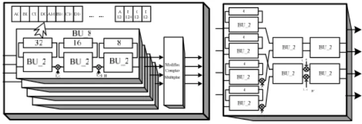
Block diagram of Module 3 is shown in Fig. 5. These four BU_8s whose structure is directly mapped from radix-23 FFT algorithm operate in the same way. The size of three
delay elements in the BU_8 is 32, 16, and eight points, respectively. The function of delay element is to store the input data until the other available input data is received for the BU_2 operation. The output data generated by the BU_2 in the first step and second step are multiplied by a trivial twiddle factor, 1, -j, 1
8
W , or 3 8
W before they are fed to the next step. But the four output data from the third step of the BU_8 need to be multiplied by the nontrivial twiddle factors simultaneously in the modified complex multipliers.
Fig. 5 (a) Block diagram of Module 3. (b) Block diagram of Module 4.
It is inefficient to build four complex multipliers for multiplying different twiddle factors simultaneously. So we modified an approach proposed by Maharatna et al. to simplify the complexity of complex multipliers [3]. The twiddle factors of the modified complex multiplier are
64p p p
W =X + jY , where p is from 0 to 49. However only nine sets of constant values, (Xp,Yp) with p=0 to 8 are needed, since the other twiddle factors can be obtained by using a mapping approach. In practice, we only need to implement eight sets of constant values, because the first set of constant value (1, 0) is trivial. And these constant values can be realized more efficiently by using several adders and shifters. The block diagram of the modified complex multiplier is shown in Fig. 6. Because different input sequences are reordered in Module 1, only the value of the twiddle factor, 4, will be used in the different path simultaneously. Thus, an additional constant multiplier, 4, is used in our design to avoid the hardware conflict as shown in Fig. 6. The gate count of this approach can save about 38% compared to four-complex-multiplier approach. And the performance of this approach is equivalent to that of the four complex multipliers. Constant 1 Constant 2 Constant 3 Constant 4 Constant 4 Constant 5 Constant 6 Constant 7 Constant 8 Mult_Re Mult_Im 1 2 Re Im 4 Re Im 3 Re Im 2 mux Sgn ( ) mux mux mux Re{Mult_Re} Im{Mult_Re} Re{Mult_Im} Im{Mult_Im} Re Im control 1 mux mux Re Im Sgn ( ) Sgn ( ) Sgn ( )
means one-data path means four-data path
Fig.6 Block diagram of the modified complex multiplier.
D. Module 4
Radix-23 FFT algorithm is realized in Module 4. The structure of the Module 4, which is shown in Fig. 5 (b) is different from that of Module 3, because the two available data of the BU_2 in the second step and third step are in the different data paths. So a suitable structure is needed to ensure the correction of the FFT output data.
E. Comparison
The proposed MRMDF architecture hardware costs in terms of 128-point FFT are:
• The number of memory: 508 (including four modules);
• Complex multipliers: 2 4 0.62+ × , where the complexity of modified complex multiplier is only 62% of that of four complex multipliers;
• Complex adders: 48.
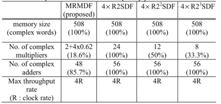
TABLE I compares the hardware requirement and throughput rate of several classical and proposed approaches in 64/128-point FFT. In general, the FFT processor dealing with 1~4 simultaneous data sequences uses the multi-processor approach. Therefore, four FFT multi-processors are needed to calculate four simultaneous data sequences for IEEE 802.11n applications. The hardware costs of the known MDC architectures like R4MDC and R2MDC [4] are very high by using multi-processor approach to deal with four data sequences. Thus, the hardware costs of these architectures are not listed in TABLE I. In this table, the numbers of complex adder and complex multiplier used in our scheme are only 85.7% and 18.6% of those in four-R2SDF approach. It is clearly seen that our proposed FFT processor can provide required throughput rate with minimal hardware cost, compared with the classical approaches.
TABLE I: Comparison of various 64/128-point pipelined FFT architectures MRMDF (proposed) 4×R2SDF 4×R2 2SDF 4 ×R23SDF memory size (complex words) (100%) 508 (100%) 508 (100%) 508 (100%) 508 No. of complex multipliers 2+4x0.62 (18.6%) 24 (100%) 12 (50%) 8 (33.3%) No. of complex adders 48 (85.7%) 56 (100%) 56 (100%) 56 (100%) Max throughput rate (R : clock rate) 4R 4R 4R 4R
IV. CHIPIMPLEMENTATION
A test chip of the multiple-input-sequence 64/128-point FFT/IFFT processor for MIMO OFDM system is designed in 0.13µm CMOS process. The core size including the test module is 2142 660× µm2 as shown in Fig 7. The function of the test module is used to save 36 chip pins and it provides one to four complex input sequences in parallel to the
FFT/IFFT processor core when the processor begins to work. The 128 points FFT with four data streams can be calculated in our proposed FFT/IFFT processor at the work frequency of 40 M Hz when it meets the 802.11n standard. In this condition, the power consumption of the proposed FFT/IFFT processor is only 5.2mW from primepower simulator.
Fig.7 Chip layout of the proposed FFT processor.
V. CONCLUSION
A novel 64/128-point FFT/IFFT processor for MIMO OFDM system has been proposed. In our proposed MRMDF architecture, simultaneous one to four input sequences can be supported. Furthermore, the hardware costs of memory and complex multiplier can be saved by adopting delay feedback and data scheduling approaches. And the number of complex multiplications is reduced effectively by using higher-radix FFT algorithm. A test chip has been designed in 0.13µm 1P8M CMOS process. Simulation result shows that the proposed FFT/IFFT processor only consumes 5.2 mW to meet the highest date rate defined in 802.11n standard.
ACKNOWLEDGMENT
This work was supported by the National Science Council of Taiwan, R.O.C. under Grant NSC93-2220-E-009-003, by the Ministry of Economic Affairs, R.O.C. under Grant 93-EC-17-A-03-S1-0005, and by the Media Tek Inc.
REFERENCES
[1] Shousheng He, and M. Torkelson, “Designing pipeline FFT processor for OFDM (de)modulation” URSI International Symposium on Signals, Systems, and Electronics, vol.29, pp. 257-262, Oct 1998. [2] Wen-Chang Yeh and Chein-Wei Jen, “High-speed and low-power
split-radix FFT,” IEEE Transactions on Acoustics, Speech, and Signal Processing, Volume.51 Issue.3, pp. 864-874, Mar 2003. [3] Koushik Maharatna, Eckhard Grass, and Ulrich Jagdhold, “A
64-Point Fourier Transform Chip for High-Speed Wireless LAN Application Using OFDM,” IEEE Journal of Solid-State Circuits, vol 39, pp. 484-493, March 2004.
[4] L. R. Rabiner and B. Gold, Theory and Application of Digital Signal Processing. Englewood Cliffs, NJ: Prentice-Hall, 1975.
[5] Yunho Jung, Hongil Yoon, and Jaeseok Kim, “New Efficient FFT Algorithm and Pipeline Implementation Results for OFDM/DMT Applications,” IEEE Transactions on Consumer Electronics, Vol. 49, pp. 14-20.