Design of a Multimode QC-LDPC Decoder
Based on Shift-Routing Network
Chih-Hao Liu, Chien-Ching Lin, Shau-Wei Yen, Chih-Lung Chen, Hsie-Chia Chang,
Chen-Yi Lee, Yar-Sun Hsu, and Shyh-Jye Jou
Abstract—A reconfigurable message-passing network is
pro-posed to facilitate message transportation in decoding multimode quasi-cyclic low-density parity-check (QC-LDPC) codes. By ex-ploiting the shift-routing network (SRN) features, the decoding messages are routed in parallel to fully support those specific 19 and 3 submatrix sizes defined in IEEE 802.16e and IEEE 802.11n applications with less hardware complexity. A 6.22-mm2
QC-LDPC decoder with SRN is implemented in a 90-nm 1-Poly 9-Metal (1P9M) CMOS process. Postlayout simulation results show that the operation frequency can achieve 300 MHz, which is sufficient to process the 212-Mb/s 2304-bit and 178-Mb/s 1944-bit codeword streams for IEEE 802.16e and IEEE 802.11n systems, respectively.
Index Terms—Architecture, IEEE 802.11n, IEEE 802.16e,
mes-sage passing, network, quasi-cyclic low-density parity check (QC-LDPC), WiMax.
I. INTRODUCTION
L
OW-DENSITY parity-check (LDPC) codes, which are de-fined by a very sparse parity check matrix, were first intro-duced by Gallager [1]. The quasi-cyclic (QC) LDPC codes are described by sparse parity-check matrices comprising blocks of circulant matrices [2]. The performance of the QC-LDPC code remains the same as the randomly constructed code, and the code length has significantly been shortened to the moderate size [3]. The QC-LDPC parity-check matrix H that can be decomposed into several cyclic-shifted identity or zero matrices is regular and applicable for hardware implementation [4], [5]. The message-passing networks can be applied to switch decoding messages between the check nodes and the bit nodes [6], [7]. However, network flexibility becomes crucial because the QC-LDPC codes in real applications have different several submatrix sizes and code rates, such as IEEE 802.16e [8] or IEEE 802.11n [9]. Thus, the multimode QC-LDPC codes defined in IEEE 802.16e and IEEE 802.11n are irregularManuscript received March 5, 2009; revised May 9, 2009 and July 9, 2009. Current version published September 16, 2009. This work supported by the National Science Council of Taiwan under Grant NSC 97-2221-E-009-166-MY3. This paper was recommended by Associate Editor V. Gaudet.
C.-H. Liu and Y.-S. Hsu are with the Department of Electrical En-gineering, National Tsing Hua University, Hsinchu 300, Taiwan (e-mail: jrhaulu@gmail.com).
C.-C. Lin, S.-W. Yen, C.-L. Chen, H.-C. Chang, C.-Y. Lee, and S.-J. Jou are with the Department of Electronics Engineering, National Chiao Tung University, Hsinchu 300, Taiwan.
Color versions of one or more of the figures in this paper are available online at http://ieeexplore.ieee.org.
Digital Object Identifier 10.1109/TCSII.2009.2027967
and difficult to support all code rates at variable submatrix sizes [10].
According to the different system parameters in IEEE 802.16e and IEEE 802.11n, the submatrix sizes defined by both of the expansion factor z and the operation mode are variable. The variety of submatrix sizes z causes difficulty in applying fixed-size crossbar switches, such as Benes network [6], [7]. There would be a large amount of interconnections in the decoder, particularly among all check nodes, bit nodes, and memory buffers [18]. Dedicated message-passing network for each specific submatrix size would also duplicate the message-passing networks, which leads to signal congestion and higher hardware complexity. The shuffle network based on Benes net-work is applied for IEEE 802.16e [19]. However, the flexibility of the shuffle network is constrained by the routing algorithm of the Benes network [19]. The matrix permutation was applied in [10] and [11] to transform the original parity-check matrix into the architecture-aware structure. After the prerescheduling for the memory access bandwidth and the hardware resource sharing, the decoder processes the specific parity check matrix. However, it is not easy to reorder all the various matrix struc-tures for all the conditions [10]. Moreover, there are 114 modes in IEEE 802.16e and 12 modes in IEEE 802.11n. Hence, a reconfigurable message-passing network is necessary for all submatrix sizes. In [12], a self-routing network is proposed to fully support the 114 different modes defined in IEEE 802.16e. Through the self-routing bits (SRBs) in the messages, the network can route messages for different submatrix sizes by using a single barrel shifter. A control circuit is required to extract the shifted messages while the shift amount is larger than half of the maximum submatrix size zmax. A shift-routing network (SRN) without SRB insertion is proposed to reduce the complexity of the routing decision rule for message passing.
Network utilization degrades the decoder throughput under smaller submatrix sizes, and the duplication of the networks can improve the throughput but makes it more complex [7]. To achieve better efficiency, the m-way duplicated network is implemented to provide parallel processing capability [13]. The network can route more messages corresponding to two or more smaller submatrices and also have the same flexi-bility as the SRN. However, the complexity of the m-way duplicated network hugely increases for the larger submatrix sizes [13].
This brief is organized as follows. Section II introduces the QC-LDPC code structure in communication systems.
TABLE I
SYSTEMPARAMETERS OFIEEE 802.16eANDIEEE 802.11n
Section III describes the architecture of the SRN. Furthermore, the SRN-based QC-LDPC decoder architecture with buffer management is presented in Section IV. The message-passing network and the decoder implementation results are shown in Section V. The final results are concluded in Section VI.
II. QC-LDPC CODES INIEEE 802.16e/IEEE 802.11n In IEEE 802.16e and IEEE 802.11n systems, the M× N parity-check matrix H can be decomposed into z× z submatri-ces, where M represents the number of parity check equations, and N represents the code length. Each submatrix is either the zero matrix or the cyclic-shifted identity matrix. A mb× nb
base matrix Hb consisting of elements 1 and 0 is expanded
to the parity-check matrix H with mb= M/z and nb= N/z.
Note that H is directly extended from the base matrix Hb
by replacing each 1 in Hb with a z× z circular right-shifted
identity matrix and each 0 in Hbwith a z× z zero matrix [13].
The maximum submatrix size zmax is defined as 96 in IEEE 802.16e and 81 in IEEE 802.11n. The code rate is determined by the value of mb/nb, where nbis 24 and the maximum value
of mbis 12 in both IEEE 802.16e and IEEE 802.11n systems.
Table I shows the system parameters of IEEE 802.16e and IEEE 802.11n. The 19 submatrix size z’s in the IEEE 802.16e specification [8] ranges from 24 to 96 with an increment of 4. In the IEEE 802.11n specification [9], the three variable z’s range from 27 to 81 with an increment of 27.
III. RECONFIGURABLEMESSAGE-PASSINGNETWORK
The z-symbol barrel shifter is applied to the QC-LDPC decoder to exchange the decoding message of the cyclic-shifted identity submatrix [14]. The self-routing network with SRB insertion was proposed in [12] to support 19 different submatrix sizes in IEEE 802.16e. Based on the 128× 128 Benes network, the shuffle network executes the 96-size permutation [19]. However, the flexibility of the shuffle network is constrained by the routing algorithm of the Benes network. In this brief, a simpler and efficient network is proposed without SRB inser-tion. Based on the barrel shifter, the SRN determines the output messages only by the shift amount p and the submatrix size z, which leads to a lower complexity.
Fig. 1 illustrates the routing algorithm of the SRN. The source message means the original input message without shifting. The barrel shifter shifts the source message according to the shift amount. The shifted message is the zmax-symbol shifter output result at the specific shift amount. We define the routing decision data as the candidate of the expected output message chosen from the shifted message. The proposed routing algorithm extracts the expected output message from
Fig. 1. Routing algorithm for the SRN.
the routing decision data. The first routing decision data are defined as the (zmax− z + 1)th to the zmaxth shifted messages, and the second routing decision data include the first to the
zth shifted messages. According to the routing algorithm, the
(z− p + 1)th to the zth expected output messages are chosen from the first routing decision data. However, the first to the (z− p)th expected output messages are chosen from the second routing decision data.
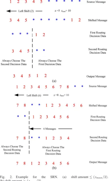
Fig. 2(a) shows an example with z = 5, zmax= 10, and
p = 2. Note that the first to fifth source messages are valid
data, and the sixth to tenth source messages denoted as “∗” are dummy data. Through the ten-symbol barrel shifter, the first routing decision data contain the eight, ninth, tenth, first, and second source messages. The second routing decision data contain the third to the seventh source messages. The first three outputs come from the second routing decision data, whereas the other two outputs are from the first routing decision data. Consequently, the expected output messages will be equivalent to those using the five-symbol barrel shifter.
Fig. 2(b) shows an example with z = 8, zmax= 10, and
p = 6. Note that p > (zmax/2). The first to seventh source messages are valid data, and the eight to tenth source messages denoted as “∗” are dummy data. The first routing decision data contain the ninth, tenth, and first to the sixth source messages. The second routing decision data comprise the seventh to the tenth and the first to the fourth source messages. Similar to the previous example in Fig. 2(a), the first two outputs are selected from the second routing decision data, and the other six outputs are the first routing decision data. By this rule, the zmax-symbol barrel shifter can work as a z-symbol barrel shifter.
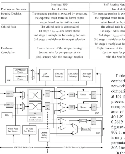
This SRN architecture is illustrated in Fig. 3. The network concurrently routes all messages through the three-stage net-work. The first stage is the zmax-symbol barrel shifter, the second stage is the circuit to generate the routing decision data, and the third stage is the selection scheme. In the final selection, the expected output messages corresponding to z (≤ zmax) are chosen from the routing decision data according to the shift amount p.
The design target of the SRN is focused on multisize message passing with lower complexity. In general, the SRN with simpler routing decision rule is suitable for the larger
Fig. 2. Example for the SRN. (a) shift amount≤ (zmax/2).
(b) shift amount > (zmax/2).
submatrix-size message passing. The comparison of the recon-figurable networks is shown in Table II.
IV. SRN-BASEDQC-LDPC DECODERARCHITECTURE
The architecture of the SRN-based QC-LDPC decoder is shown in Fig. 4. The main operation circuit includes two node processors. The first processor is the check-node proces-sor (CNP), which is used in the first phase, and the second processor is the bit-node processor (BNP), which accumu-lates messages in the second phase. The decoding messages exchanged between CNP and BNP can be routed with our proposed networks. To comply with the different code rates, the decoder keeps the shift amounts of each submatrix at different code rates in the read-only memory. The memory blocks are applied to store both the decoding message and the received channel values. The buffer management unit (BMU) will con-trol the CNP/BNP memory access and manage the memory bandwidth.
There are two decoding cycles for CNP and BNP to process two submatrices. The first cycle is the switch cycle for passing
Fig. 3. Structure of the SRN.
the message with flexible networks. However, the second cycle is the processing cycle for the operation of CNP sorters and BNP accumulators. The latency for memory access can be eliminated by the memory prefetch function in BMU.
In the sum-product algorithm (SPA) [1], the decoding speed is restricted due to the data dependency between the bit node and the check node. In the proposed decoder, both the check node and the bit node can be overlapped since the parity-check matrix H is decomposed into submatrices. The decoding process and the buffer management can be partitioned into several subiterations based on the row index. The subiteration includes four stages: 1) initial memory pre-fetch; 2) CNP/BNP switch; 3) CNP/BNP operation; and 4) new message updating. The sign magnitude (SM) transformation converts the incoming message from the SM notation to the 2’s complement (TC). The new messages from CNP or BNP that will be updated are completely processed.
Two message-passing networks are implemented in the pro-posed decoder. Therefore, the amount of parallelism in this decoder is defined as “two,” and two message groups corre-sponding to two submatrices will concurrently be processed. The maximum row number in the parity-check matrix is defined as nrow. The cycle ksub, which is required to complete each subiteration, is
ksub= 1 +
nrow
2 . (1)
Note that the first term in (1) is the latency of the check node operation in the first two rows. Accordingly, the total latency
TABLE II
COMPARISON OF THERECONFIGURABLENETWORK
Fig. 4. Architecture of SRN-based QC-LDPC decoder.
Titerfor one iteration is expressed as
Titer= ksub× (tinit+ 2ncol+ twb). (2) In the initialization cycles tinit= 4, the first two cycles are ap-plied to clear the register content of the previous row operation, and the last two cycles are applied to prefetch the memory. The latency 2ncol is required to complete ncol submatrices in each row, because the networks should be shared between the CNP and the BNP. Note that ncol is equal to 24 in both IEEE 802.16e and IEEE 802.11n systems. The decoder needs additional latency twb= 2 to write the new check node message back to the minimum message memory. Finally, the throughput rate of the decoder can then be calculated by
ncol× z × fclk
Titer× l
(3) where fclkis the clock frequency, and l is the iteration number.
ncol× z represents the decoding bit number at the specified iteration number l. Note that the decoder throughput depends on not only the latency Titerbut also the column number ncol,
z, and the iteration number l.
V. IMPLEMENTATIONRESULT
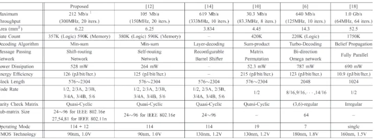
Table III summarizes the synthesis area and the performance comparison among the SRN and the existing message-passing networks in the literature [12]–[14], [16], [17], [19]. For a fair comparison, networks with 9-bit word length are synthesized at the maximum operation frequency in the 130-nm CMOS process without any timing violation [12], [13]. The SRN occupies 0.1358 mm2 (500 MHz, 27.1-K gates), whereas the area of the self-routing network is 0.1808 mm2 (442 MHz, 40.1-K gates), and the m-way duplicated network occupies 0.2619 mm2 (460 MHz, 52.3-K gates, m = 2). The recon-figurable permuter in [16] only supports three z’s in IEEE 802.11n. The 6-bit shuffle network gate count is 16 k, but it is only compliant with IEEE 802.16e [19]. With a barrel-shifter permutation network, the proposed SRN fulfills all z’s in IEEE 802.16e and IEEE 802.11n.
In the 90-nm 1P9M process, the decoder chip with the SRN occupies 6.22-mm2 silicon area and can achieve 300 MHz in the postlayout simulation. This chip includes 357-K logic gates and 590-K memory. For decoding the rate-5/6 2304-bit code by the min–sum algorithm, the (114 + 12)-mode decoder achieves the maximum 212-Mb/s data rate within 20 iterations and dissipates 528 mW at 1.0-V supply. Table IV shows the performance comparison between our proposed decoder and other solutions published in [6], [10], [12], [14], and [18]. With layer decoding, the decoder in [14] improves the throughput and complexity with ten iterations. The decoder complexity in [14] is less, and only 19 modes are supported. The maximum operating frequency in [12] is only 150 MHz, which seems to be constrained by the input–output pads of self-routing-network-based decoder chip. In addition, the complexity of the proposed decoder is reduced from 380 K to 357 K when two self-routing networks are replaced by SRNs.
VI. CONCLUSION
A reconfigurable message-passing network architecture has been proposed for decoding QC-LDPC codes. Based on the simpler routing decision, the complexity of the proposed message-passing network applied for 19 + 3 different net-work sizes in IEEE 802.16e and IEEE 802.11n can signifi-cantly be reduced. As compared with other networks for the LDPC decoder, the proposed SRN can support the permutation
TABLE III
COMPARISON OFMESSAGE-PASSINGNETWORK FORLDPC DECODER
TABLE IV
COMPARISON OFQC-LDPC DECODERS
function to fulfill the requirement of various submatrix sizes with less complexity. Hence, our proposal is very suitable for those applications with multimode QC-LDPC decoder requirements.
REFERENCES
[1] R. Gallager, “Low-density parity-check codes,” IEEE Trans. Inf. Theory, vol. IT-8, no. 1, pp. 21–28, Jan. 1962.
[2] M. P. C. Fossorier, “Quasicyclic low-density parity-check codes from circulant permutation matrices,” IEEE Trans. Inf. Theory, vol. 50, no. 8, pp. 1788–1793, Aug. 2004.
[3] L. Chen, J. Xu, I. Djurdjevic, and S. Lin, “Near-Shannon-limit quasi-cyclic low-density parity-check codes,” IEEE Trans. Commun., vol. 52, no. 7, pp. 1038–1042, Jul. 2004.
[4] L. Yang, H. Liu, and C. J. R. Shi, “Code construction and FPGA imple-mentation of a low-error-floor multi-rate low-density parity-check code decoder,” IEEE Trans. Circuits Syst. I, Reg. Papers, vol. 53, no. 4, pp. 892–904, Apr. 2006.
[5] C. P. Fewer, M. F. Flanagan, and A. D. Fagan, “A versatile variable rate LDPC codec architecture,” IEEE Trans. Circuits Syst. I, Reg. Papers, vol. 54, no. 10, pp. 2240–2251, Oct. 2007.
[6] M. M. Mansour and N. R. Shanbhag, “A 640-Mb/s 2048-bit program-mable LDPC decoder chip,” IEEE J. Solid-State Circuits, vol. 41, no. 3, pp. 634–698, Mar. 2006.
[7] J. Tang, T. Bhatt, V. Sundaramurthy, and K. K. Parhi, “Reconfigurable shuffle network design in LDPC decoders,” in Proc. 17th Int. Conf.
Appl.-Specific Syst. Process., Sep. 2006, pp. 81–86.
[8] Part 16: Air Interface for Fixed and Mobile Broadband Wireless Access
Systems Amendment for Physical and Medium, IEEE P802.16e-2005,
Oct. 2005.
[9] IEEE 802.11 Wireless LANs WWiSE Proposal: High Throughput
Exten-sion to the 802.11 Standard, IEEE 11-04-0886-00-000n, 2004.
[10] X. Y. Shih, C. Z. Zhan, C. H. Lin, and A. Y. Wu, “A 19-mode 8.29 mm 52-mW LDPC decoder chip for IEEE 802.16e system,” IEEE J.
Solid-State Circuits, vol. 43, no. 3, pp. 672–683, Mar. 2008.
[11] S. H. Kang and I. C. Park, “Loosely coupled memory-based decod-ing architecture for low density parity check codes,” IEEE Trans.
Circuits Syst. I, Reg. Papers, vol. 53, no. 5, pp. 1045–1056,
May 2006.
[12] C. H. Liu, S. W. Yen, C. L. Chen, H. C. Chang, C. Y. Lee, Y. S. Hsu, and S. J. Jou, “An LDPC decoder chip based on self-routing network for IEEE 802.16e applications,” IEEE J. Solid-State Circuits, vol. 41, no. 3, pp. 684–694, Mar. 2008.
[13] C. H. Liu, C. C. Lin, H. C. Chang, C. Y. Lee, and Y. S. Hsu, “Multi-mode message passing switch networks applied for QC-LDPC decoder,” in Proc. IEEE ISCAS, May 2008, pp. 752–755.
[14] T. Brack, M. Alles, F. Kienle, and N. When, “A synthesizable IP core for WiMAX 802.16E LDPC code decoding,” in Proc. IEEE 17th Int. Symp.
Pers., Indoor, Mobile Radio Commun., Sep. 2006, pp. 1–5.
[15] D. E. Hocevar, “A reduced complexity decoder architecture via layered decoding of LDPC codes,” in Proc. IEEE Workshop Signal Process. Syst., Oct. 2004, pp. 107–112.
[16] M. Karkooti, P. Radosavljevic, and J. R. Cavallaro, “Configurable, high throughput, irregular LDPC decoder architecture: Tradeoff analysis and implementation,” in Proc. 17th Int. Conf. Appl.-Specific Syst. Process., 2006, pp. 360–367.
[17] M. Rovini, G. Gentile, and L. Fanucci, “Multi-size circular shifting net-works for decoders of structured LDPC codes,” Electron. Lett., vol. 43, no. 17, pp. 938–940, Aug. 2007.
[18] A. J. Blanksby and C. J. Howland, “A 690 mW 1 Gb/s 1024b rate 1/2 low density parity check code decoder,” IEEE J. Solid-State Circuits, vol. 37, no. 3, pp. 404–412, Mar. 2002.
[19] J. Lin, Z. Wang, L. Li, J. Sha, and M. Gao, “Efficient shuffle net-work architecture and application for WiMAX LDPC decoders,” IEEE
Trans. Circuits Syst. II, Exp. Briefs, vol. 56, no. 3, pp. 215–219,
![Table I shows the system parameters of IEEE 802.16e and IEEE 802.11n. The 19 submatrix size z’s in the IEEE 802.16e specification [8] ranges from 24 to 96 with an increment of 4](https://thumb-ap.123doks.com/thumbv2/9libinfo/7571991.125335/2.891.56.431.138.218/table-shows-parameters-submatrix-ieee-specification-ranges-increment.webp)