Journal of Materials Processing Technology 192–193 (2007) 200–203
Analysis of draw-wall wrinkling in the stamping of a motorcycle oil tank
Fuh-Kuo Chen
∗, Yeu-Ching Liao
∗∗Department of Mechanical Engineering, National Taiwan University, Taipei, Taiwan, ROC
Abstract
In the present study, the wrinkling problem occurred in a stamping part used for a motorcycle oil tank was studied using the 3-D finite element analysis. The material flow due to the original die design was first examined and the possible reasons causing the wrinkling problem were then identified based on the finite element analysis. In order to eliminate the wrinkles, the effects of the process parameters such as blank-holder force, blank size and draw-bead locations on the formation of wrinkling were studied and possible solutions were tried. However, the wrinkle problem could not be improved by changing the process parameters only. A detailed investigation on the material flow during the wrinkle formation process revealed that the uneven stretch between the highest portion of the part and the draw-wall at the part edge caused the wrinkling problem. After releasing the corner angle and cutting off some portion of the sharp corner, a sound part without wrinkles was achieved and the optimum die shape was determined. The modified die design for eliminating wrinkles is validated by the defect-free production part. The good agreement between the simulation results and the measured data obtained from the defect-free production part confirms the accuracy of the finite element analysis. © 2007 Elsevier B.V. All rights reserved.
Keywords: Draw-wall; Wrinkles; Stamping die design; Optimum design; Finite element analysis
1. Introduction
In the stamping of a product with a complex shape, wrin-kling is one of the major defects that occur in the forming process. For both functional and visual reasons, wrinkles are usually not acceptable in a finished part. There are three types of wrinkles which frequently occur in the sheet-metal forming process: flange wrinkling, wall wrinkling, and elastic buckling in the undeformed area due to residual elastic compressive stresses. The draw-wall wrinkling means the occurrence of wrinkles in the die cavity, such as the wrinkling in a motorcycle oil tank shown inFig. 1. It is well known that additional stretching of the mate-rial in the unsupported wall area may prevent wrinkling, and this can be achieved in practice by increasing the blank-holder force. However, the application of excessive tensile stresses leads to failure by tearing. Hence, the blank-holder force must lie within a narrow range, above that necessary to suppress wrinkles on the one hand, and below that to produce fracture on the other. This narrow range of blank-holder force is difficult to determine. Since the sheet metal in the draw-wall area is relatively unsup-ported by the tool, the elimination of draw-wall wrinkles is even more difficult than the suppression of flange wrinkles.
∗Corresponding author. Tel.: +886 2 23661322; fax: +886 2 23631755. ∗∗ Corresponding author.
E-mail address:fkchen@ntu.edu.tw(F.-K. Chen).
In order to examine the mechanics of the formation of wrinkles, Tugu et al.[1]investigated the wrinkle formation ten-dencies in the form of short-wavelength shallow buckling modes for sheet materials exhibiting planar anisotropy. Yoshida et al.
[2] proposed an approximate theoretical model in which the onset of wrinkling is due to the elastic buckling resulting from the compressive lateral stresses developed in the non-uniform stress field. Yu and co-workers[3,4]investigated the wrinkling problem both experimentally and analytically. They found that wrinkling could occur with a number of circumferential waves equal to two according to their theoretical analysis, while the experimental results indicated a number ranging from 4 to 6. Narayanasamy and Sowerby[5]examined the wrinkling of sheet metals when drawing through a conical die using flat-bottomed and hemispherical-ended punches. Jinta et al.[6]examined the wrinkle behavior in forming various 5000 and 6000 series alu-minum alloy sheets and compared the results with those obtained with mild and high-tensile steels. They found that aluminum alloy generally forms more wrinkles than steel, especially in the 6000 series aluminum alloy. The research focused on improv-ing the predictability of wrinklimprov-ing occurrence by usimprov-ing the static explicit finite element simulation of stamping a dual phase rail part was conducted by Banu et al.[7]. The proposed solution for simulation includes algorithms implemented in the finite ele-ment code which makes possible the obtaining of more accurate prediction results.
0924-0136/$ – see front matter © 2007 Elsevier B.V. All rights reserved. doi:10.1016/j.jmatprotec.2007.04.100
F.-K. Chen, Y.-C. Liao / Journal of Materials Processing Technology 192–193 (2007) 200–203 201
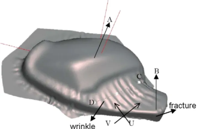
Fig. 1. Appearance of wrinkle and fracture.
In the present study, a wrinkling problem occurred in a stamp-ing part used for a motorcycle oil tank was examined usstamp-ing the 3-D finite element analysis. In the stamping process with the original die design, wrinkles appear in the production part, as shown in Fig. 1. The material flow due to the original die design was first examined and the possible reasons causing the wrinkling problem were identified based on the finite element analysis. A detailed investigation on the material flow during the formation of wrinkles was performed to determine the major rea-son for the occurrence of wrinkles. An optimum die design was then proposed to eliminate the wrinkles in the stamping process, and the validity of the finite element analysis was confirmed by the defect-free production part.
2. Finite element model
The tooling geometry, including the punch, die and blank-holder, were constructed by the CAD program PRO/ENGINEER. Both the 3-node and 4-node shell elements were adopted to generate the mesh systems for the above tooling using the same CAD program. In the finite element simula-tions, the tooling is considered to be rigid, and the corresponding meshes are used only to define the tooling geometry and are not for the stress analysis. The same CAD program using the 4-node shell element was employed to construct the mesh system for the sheet blank.Fig. 2shows the mesh system for the complete
Fig. 2. Finite element model for the original die design.
Fig. 3. The stress–strain relations of SPCEN steel.
set of tooling and the sheet-blank used in the stamping of the motorcycle oil tank. In the simulation, the sheet blank is put on the blank-holder and the die is moved down to clamp the sheet blank against the blank-holder. The punch is then moved up to draw the sheet metal into the die cavity.
The cold rolled steel of SPCEN grade was used as the blank material. The stress–strain relations of the blank sheet, as shown inFig. 3, obtained from the tensile tests performed in the present study was adopted for the finite element simulations. The coef-ficient of Coulomb friction was assumed to be 0.1 and the punch speed was set to 10 m/s. The finite element program PAM STAMP was employed to conduct the simulations and all the simulations were run on a desktop PC.
3. Analysis of wrinkle formation in the original die design
The finite element simulations were performed to analyze the deformation mechanics in the formation of wrinkles caused by the original die design. The finite element model constructed according to the original die shapes is shown inFig. 2. It is noted that a feature shape is added to the die addendum in addition to draw-bead around the periphery of the die cavity that are sup-posed to control the material flow into the part shape. However, the finite element simulation result reveals that both wrinkles and fracture are observed in the deformed shape, as indicated inFig. 1. Fracture at location B, as shown inFig. 1, may be attributed to a small corner radius or a larger blank-holder force applied, which is easy to cope with. But the wrinkles in the C–D area, as shown inFig. 1, were not expected in the design stage. In order to determine the possible reasons that cause wrinkles, the strain history of elements in the C–D area was examined.
Fig. 4shows the plot of major and minor principal strains of an element in the C–D area during the stamping process. It is noticed inFig. 4 that the difference of the major and minor principal strains increases abruptly when the punch contacts the blank at point B, which implies a dramatic shape change at this point. A detailed examination of the deforming shape change during the stamping process confirms that wrinkles are formed, as shown inFig. 5, when the punch travels to a position where the sheet blank contacts the punch at point B. Before this contact point, no wrinkle appears. The wrinkles in area C–D are obvi-ously draw-wall wrinkles, since there is no support of die surface in this area. The sheet-metal in this area is pulled in the direction
202 F.-K. Chen, Y.-C. Liao / Journal of Materials Processing Technology 192–193 (2007) 200–203
Fig. 4. Strain history of an element in the wrinkling zone.
indicated by U and is compressed in the direction denoted by V, as shown inFig. 1. These two directions are also the principal directions, and the abrupt change of the principal strains in these two directions, as shown inFig. 4, indicates that the dramatic increase of compressive lateral strain leads to the formation of wrinkles.
In order to eliminate the wrinkles, the effects of the process parameters, such as blank-holder force, blank size and draw-bead restraining force on the formation of wrinkling were studied and possible solutions were tried. However, the finite element simulations results indicate that wrinkles could not be com-pletely eliminated by adjusting the above process parameters. On the contrary, the fracture problem becomes more serious. In addition, the corner radius at location B was also enlarged to help the material flow, but the fracture problem could not be eliminated.
4. An optimum die design
A detailed investigation on the material flow during the wrin-kle formation process revealed that the uneven stretch between the highest portion of the part, point A, and the draw-wall at the part edge, point B, as shown inFig. 5, might be the critical reason causing the wrinkling problem. The finite element analysis was then employed to examine the effect of the die geometry on the formation of wrinkles. The trim line, which defines the bound-ary of the product shape on the die surface, was first identified
Fig. 5. Wrinkle formation after the contact of point B.
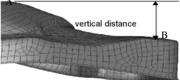
Fig. 6. The vertical distance between points A and B.
and modifications on the die surface outside the trim line, which is termed addendum, were then made according to the finite ele-ment simulation results. It is inferred from Figs. 4 and 5that wrinkles could be eliminated if the punch-blank contact at loca-tion B is delayed and the contact area is increased. That means the vertical distance between points A and B, as shown inFig. 6, should be increased and the corner radius at point B needs to be more generous to enlarge the contact area. In addition, a larger corner radius at location B also helps to avoid the occurrence of fracture.
The finite element simulations were performed for various corner radii at point B in a selected increment from the original corner radius of 15 mm. The principal strain distributions along the cross section C–D obtained from the finite element simu-lation for the corner radius of 30 mm at location B, as shown inFig. 7, reveal that the values of compressive strain are in a moderate range. The simulation results also show a significant improvement on the elimination of wrinkles with the increase of the corner radius. However, wrinkles still could not be com-pletely suppressed. A further investigation on the die surface with various corner radii found that a replacement of the sharp corner by an inclined flat surface could increase the vertical distance between points A and B and the contact area between punch and sheet-blank at point B to a relatively maximum value. The distance between points A and B increases from 98.69 to 123 mm as the original corner radius of 15 mm is changed to an inclined flat surface, the distance between points A and B being 110 mm for corner radius of 30 mm. The finite element simulation results revealed that both wrinkles and fracture were eliminated with the above design. To complete the die design, the blank shape was modified as well to a suitable shape with smaller dimensions. An optimum die design was then achieved by the finite element analysis.
Fig. 7. The distribution of major and minor strain on section C–D for corner radius of 30 mm.
F.-K. Chen, Y.-C. Liao / Journal of Materials Processing Technology 192–193 (2007) 200–203 203
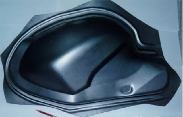
Fig. 8. A sound production part without wrinkles and fracture.
Fig. 9. Thickness distribution along the wrinkling area.
A production die set was manufactured according to the opti-mum design and a sound part without wrinkles and fracture was produced, as shown inFig. 8. The thickness distribution along C–D was measured from the production part and compared with that obtained from the finite element simulation, as shown in
Fig. 9. It is seen inFig. 9that the trend of thickness distribution obtained from the finite element simulation is consistent with that measured from the production part, but with higher values. However, the discrepancy in the value of thickness is not signif-icant. The good agreement between the simulation results and
those measured in the drawn production part thus demonstrates the accuracy of the finite element analysis.
5. Concluding remarks
The draw-wall wrinkle occurred in the stamping of a motorcy-cle oil tank part was analyzed by the finite element simulations. The finite element analysis indicates that an uneven stretch between two unleveled portions is the major reason to cause the wrinkle problem. It therefore implies that uneven stretch in a stamped part is apt to inducing wrinkles. A detailed investi-gation on the material flow for the onset of wrinkle formation reveals that an increase of the vertical distance between the two unleveled portions, and an enlargement of the contact areas at the critical location are found to be very effective in eliminating wrinkles due to the uneven stretch. The defect-free production part and the good agreement between the simulation results and measured data confirm the effectiveness of using the finite ele-ment simulations as a substitute for the expensive method of actual die try-outs.
Acknowledgements
The authors wish to thank the National Science Council of the Republic of China for the grant NSC-86-2212-E002-028 that made this project possible. They also wish to thank KYM for providing the production part. The help from ESI in running the PAM STAMP program is highly appreciated as well.
References
[1] P. Tugu, K.W. Neale, P.D. Wu, S.R. MacEwen, Int. J. Mech. Sci. 43 (12) (2001) 2883–2897.
[2] K. Yoshida, H. Hayashi, K. Miyauchi, Y. Yamato, K. Abe, M. Usuda, R. Ishida, Y. Oike, Scient. Papers, Inst. Phys. Chem. Res. 68 (1974) 85–93. [3] T.X. Yu, W. Johnson, W.J. Stronge, Int. J. Mech. Sci. 26 (1984) 131–148. [4] W.J. Stronge, M.P.F. Sutcliffe, T.X. Yu, Exp. Mech. (1986) 345–353. [5] R. Narayanasamy, R. Sowerby, J. Mater. Proc. Tech. 41 (1994) 275–290. [6] M. Jinta, Y. Sakai, M. Oyagi, S. Yoshizawa, K. Matsui, K. Noda, JSAE Rev.
21 (3) (2000) 407–409.
[7] M. Banu, M. Takamura, T. Hama, O. Naidim, C. Teodosiu, A. Makinouchi, J. Mater. Proc. Tech. 173 (2) (2006) 178–184.