Frequency Syntonization Using GPS Carrier Phase
Measurements
Kun-Yuan Tu, Fan-Ren Chang, Chia-Shu Liao, and Li-Sheng Wang
Abstract—A new methodology of frequency syntonization using a global positioning system (GPS) carrier phase double differences is presented. The proposed scheme can achieve the traceability of frequency dissemination and obtain the very high frequency sta-bility in the short term, as well as in the long term. The GPS re-ceivers used in our system were elaborately modified in order to es-timate the frequency offset of the remote low-cost oven-controlled crystal oscillator (OCXO) clock with respect to the primary cesium atomic clock in real time by performing the double differences on the GPS carrier phase observables. The fuzzy controller and the proportional-derivative (PD) controller were employed to imple-ment the controllers of our system, respectively. Through the D/A converter, the remote clock was then steered to synchronize with the primary clock. For averaging times of one day under the con-figuration of about a 30-m baseline, our experimental results show that the accuracy of the remote clock can be improved from about 3 10 9to about 3 10 14, and the stability of the remote clock can be improved from about 3 10 10to about 2 10 14. More-over, the 30-m baseline tests with the common high-performance cesium clock revealed that our system has a frequency stability of about 2 10 16for averaging times of one day.
Index Terms—Frequency accuracy, frequency stability, fre-quency syntonization, GPS carrier phase.
I. INTRODUCTION
T
HE frequency source (FS) plays a key role in many applications, such as telecommunication networks, power systems, navigation systems, automotive systems, instrumenta-tion systems, and Doppler radars, etc. Requirements for primary reference sources (PRS) in the telecommunication networks are given in [11]. That is, the maximum allowable fractional frequency offset for observation times greater than one week is 1 10 over all applicable operational conditions. To achieve the requirements for PRS, the expensive, high-perfor-mance rubidium or cesium clock may be adopted. FSs such as quartz or rubidium, which are installed inside automotive systems, instruments, and other systems, must be both routinely and off-line calibrated in calibration laboratories so that they remain within the tolerance required by the user’s application. In addition, FSs used for calibration laboratories must be traced to national or international standards. Using global positioning system disciplined oscillators (GPSDOs) based on C/A code observations is one of the principal methods of maintaining worldwide high–accuracy time and frequency dissemination. However, GPSDOs are subject to errors or biases such asManuscript received May 26, 1999; revised December 13, 2001. This work was supported by the National Bureau of Standards of the R.O.C.
The authors are with the Department of Electrical Engineering, National Taiwan, University, Taipei, Taiwan, R.O.C.
Publisher Item Identifier S 0018-9456(01)04391-1.
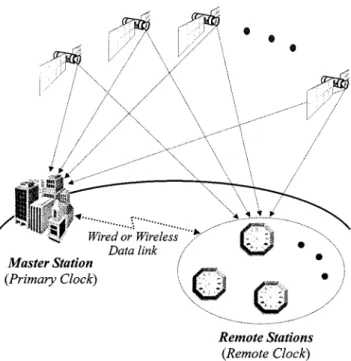
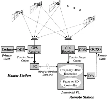
Fig. 1. System architecture for the frequency syntonization using the GPS carrier phase measurements.
effects from selective availability (SA), atmosphere, and others. Thus, the performance of GPSDOs is limited. Furthermore, the uncertainty budget of the overall system is necessarily assessed when the traceability is considered. However, it is difficult to evaluate the uncertainty of GPSDOs, since the global posi-tioning system (GPS) is under the direct control of the United States military. Therefore, GPSDOs have not been recognized yet as traceable standards. Recommendations made on the suitability of GPSDOs as traceable standards are currently under investigation at the National Physical Laboratory (NPL), Teddington, U.K. [5].
The capability of using GPS carrier phase, rather than C/A code with the common-view technique to transfer precise time and frequency, has been recognized and described by many researchers [6]–[8]. Because the frequency of the carrier is roughly 1000 times higher than that of the C/A code, time and frequency dissemination using the carrier phase have a much greater resolution, in principle. In this paper, a new scheme for frequency syntonization using GPS carrier phase double differences is proposed. The basic architecture of the system is shown in Fig. 1. With all-in-view observations, the frequency offset of the remote clock with respect to the primary clock is estimated in real time by performing the carrier phase single difference (difference between two receivers with the same 0018–9456/01$10.00 © 2001 IEEE
satellite) and time difference (difference between two epochs). Through these kinds of double differences, the errors and biases that affect the measurements are substantially reduced. In our system, the GPS carrier phase data and other observation messages are passed between both stations through Internet and public switched-telephone network (PSTN). The frequency offset and its change with respect to time of the remote clock are then fed into the controller, which automatically issues commands to steer frequency syntonization with the primary clock. On the other hand, the master station can also monitor the performance of the remote clock in real time. Both a fuzzy algorithm and a classical proportional derivative (PD) algorithm are considered in our paper. From the experimental results, both controllers work well.
With the above-mentioned method, the accuracy of the re-mote oven-controlled crystal osciallator (OCXO) clock could be improved from about 3 10 to about 3 10 for av-eraging times of one day. The stability of the remote OCXO clock could be improved from about 3 10 to about 2 10 . Our experiments show that the proposed architecture is sound and cost-effective. The potential roles of our system in-clude the PRSs for telecommunication networks and the FSs for calibration laboratories, power systems, navigation systems, in-strument calibration, and others.
This paper is organized as follows:
1) Section II presents models of GPS carrier phase observ-ables.
2) Section III describes the system architecture. 3) The experimental results are illustrated in Section IV. 4) Finally, the concluding remarks are given in Section V.
II. MODEL OFGPS CARRIERPHASEOBSERVABLES The typical model of GPS carrier phase observables [1], [2] is
(1) where
carrier phase measurement of the receiver from the th GPS satellite in the meter; true distance between the receiver and the
th GPS satellite; speed of light;
clock bias of the th satellite;
the clock difference between the GPS time and receiver clock;
GPS carrier wavelength; initial phase integer ambiguity;
and ionospheric delay and the tropospheric
delay, respectively;
unmodeled error primarily due to multipath, temperature variation, physical factors, etc. To study the frequency syntonization, we would like to first examine the behavior of the oscillator. Hence, the GPS receiver’s internal clock will be replaced by an external one. Under this arrangement, the term in (1) represents the time difference between the GPS clock and the external clock
Fig. 2. Relationship between external clockA and external clock B.
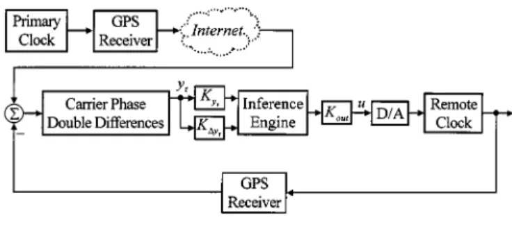
Fig. 3. Functional block diagram for the frequency syntonization using the GPS carrier phase measurements.
. Denoting the two receivers by and and the satellite by , respectively, the single-difference equation is
(2) where represents the operator for differences between re-ceivers with the same satellite. Due to the strong correlation be-tween the unmodeled ionospheric and tropospheric delays of the two receivers over a short baseline, the terms and in (1) are then eliminated.
Since and are both referring to the same GPS clock, their difference in (2) is nothing but the phase differ-ence between external clock and external clock , cf. Fig. 2. On the other hand, if the satellite signal is continuously tracked and there is no cycle slip occurring, the difference of cycle am-biguities remains a constant. Accordingly, we may take another difference on (2) with respect to different times to get the time-difference model
(3) where denotes the operator for differences between two epochs.
III. SYSTEMARCHITECTURE
Fig. 3 shows the functional block diagram of our system. It consists of the master station and the remote station. The
master station contains the high-performance cesium clock, di-rect digital synthesizer (DDS), GPS receiver, and PC. The re-mote station includes the low-cost oven-controlled crystal os-cillator (OCXO), DDS, GPS receiver, D/A converter, and in-dustrial PC. Through the wired or wireless data links, the car-rier phase data and other GPS observation messages can be sent between both stations.
In order to estimate the offset of the remote clock with re-spect to the primary clock (cesium), they are connected to GPS receivers, respectively. Hence, the original internal quartz oscil-lator in each receiver is replaced. By the help of the frequency synthesizer (i.e., the DDS), the signal of the external clock can be appropriately converted and then supplied to the GPS re-ceiver.
The frequency offset of the remote clock with respect to the primary clock can be estimated by performing the single differ-ence [i.e., (2)], and then the time differdiffer-ence [i.e., (3)], on carrier phase observables. In the process, the biases and errors from satellites and receivers can be significantly reduced. (3) can be further expressed as follows:
(4) in which the left-hand side of the equation is the difference of measured data and known values. The coordinates of the GPS antenna are predetermined by the international GPS ser-vice (IGS), and the coordinates of the th GPS satellites are ob-tained from the broadcast navigation messages. However, some errors affecting the estimation of the frequency offset may occur in the evaluation of the right-hand side.
This term ,
where can be obtained by averaging (4) for
all-in-view GPS observations. As previously mentioned, since is the phase difference between primary clock and remote clock, the associated frequency offset is
(5) In general, the fine frequency tuning can be performed on the inexpensive oscillator through voltage control. Because of environmental effects such as vibration, temperature, pressure, and humidity, the desired frequency output is not always under a constant voltage.
In our system, the frequency offset and its change are chosen as the input vari-ables of the controllers. Two approaches, fuzzy and PD, will be considered as control laws later. An incremental voltage will be generated to update the voltage for steering the oscillator
(6) For the low-cost quartz or rubidium oscillator, the frequency offset may vary over very large scales. The logarithmic function is therefore employed to map the estimated and to yield the mapping function as follows:
(7)
Fig. 4. Fuzzy control block diagram.
Fig. 5. Membership functions used for input and output.
where represents or ; and are the scaling factor
and the offset factor, respectively. The values of or may be chosen based on the hardware. In our experiments, by noting that the frequency offset of the inexpensive oscillator is about 1 10 in the worst case, and the carrier phase measurements precision of the Ashtech™ G-12 GPS receiver is about 0.9 mm
(i.e., 3 10 in seconds), we chose the and as 3
10 and 1 10 , respectively.
In our system, we considered the typical fuzzy control [3] and the PD control [4] in the remote clock. In fact, there are many other control algorithms which can be used here.
A. Fuzzy Controller
The block diagram of the fuzzy controller applied in our system is shown in Fig. 4. The inference engine part in Fig. 4 contains the knowledge-base of a fuzzy controller, which is composed of two components, the data base and the fuzzy control rule base.
The input space is divided into five sets: 1) negative big (NB);
2) negative small (NS); 3) zero (ZE);
4) positive small (PS);
5) positive big (PB) for a frequency offset or its change. We choose triangular-shaped membership functions (MFs) for the control input variables due to their simple structure and com-putation. The input and output membership functions are de-picted in Fig. 5. In order to provide precise control, the sets were designed to be closer to the desired value of zero.
Fig. 6. Fuzzy rule table.
Fig. 7. PD control block diagram.
The control output is determined from the center-average method formulated as follows:
(8)
where
output control gain; grade of the th output MF;
output label for the value contributed by the th MF; number of contributions from the rules.
The rules in the fuzzy controller are based on the process fre-quency offset and its change . These rules are expressed as
The rule table is shown in Fig. 6. B. PD Controller
The PD controller is typical in many industrial applications. The block diagram for the PD controller used in our experiment is shown in Fig. 7. The control signal is a linear combination of the frequency offset and the change with gains and being adjustable. To design a particular control loop for the frequency syntonization applications, we merely have to adjust the constants and in Fig. 7 to achieve an acceptable level of performance. With some trial and error, both parameters are appropriately determined, and excellent results similar to the system using the fuzzy control algorithm are obtained.
IV. EXPERIMENTALRESULTS
The basic experimental structure for tests is shown in Fig. 3 in Section III. The Ashtech™ G-12 GPS receivers installed in
Fig. 8. Frequency stability analysis of the free running OCXO (OCXO line), GPSDO (GPSDO line) and the OCXO under control (OCXO-C line).
Fig. 9. Frequency stability analysis of our system by using the common high-performance cesium clock (HP5071A) over about a 30-m baseline.
our system were not designed for time and frequency applica-tions. They have no interface ports for external clocks. In order to use the G-12 receivers to establish the system of frequency syntonization, we replaced the 20.460 MHz internal quartz os-cillator of the receiver with the external frequency source. In the master station, the 10 MHz of the high-performance ce-sium clock (HP5071A) used as primary clock was converted to 20.460 MHz through a DDS manufactured by NOVATECH™, Model DDS5m, and then connected to a G-12 receiver. The OCXO manufactured by Datum™, Model FTS 1130, was used as remote clock. The DDS and the G-12 receiver in the remote station were used to perform the same function as those in the master station. The carrier phase data and other GPS observa-tion messages were passed between both staobserva-tions through the Internet interface.
In our experiment, the software, including the fuzzy con-troller and PD concon-troller, communication interfaces such as the
Internet and PSTN, and data collection, were programmed in C on Windows 98 and executed on an industrial PC manufactured by ADVANTECH™. The data used for frequency accuracy and stability analysis were measured every one second by a time in-terval counter (TIC) manufactured by SRS™, model SR620.
By performing the linear-least-square fit on the frequency data over some observation intervals (e.g., one day), we can
es-timate the frequency accuracy , where is the
amount of phase deviation, and is the observation interval. Ac-tually, the linear-least-square fit is commonly adopted in many frequency calibration systems, such as the frequency measure-ment and analysis system (FMAS) manufactured by the U.S. National Institute of Standards and Technology (NIST). In ad-dition, for the stability analysis of the frequency source under tests, we made use of the IEEE recommended modified Allan deviation (MDEV) [10], which is a standard practice in the time and frequency community. In our experiment, the confidence intervals applied to the frequency stability analysis were set to
68%.
We examined the performance of the free running OCXO used in our system and a GPSDO manufactured by Taiclock™, GDOX-2000S, in order to compare the results with the perfor-mance of the OCXO under control. These frequency analyzes are shown in Fig. 8.
The GPSDO line shows that the performance of the GPSDO is significantly degraded over these averaging times between 50 s and 10 000 s. Over these averaging times, the GPSDO was not a stable time and frequency source due to the SA and the atmos-phere effects, although it showed good long-term performance. The OCXO line in Fig. 8 shows the frequency instability. The OCXO-C line shows the typical results of a frequency stability analysis of the remote OCXO clock under control. These results reveal the high frequency stability of the remote clock not only over the short term, but also over the long term. The frequency stability of the OCXO clock could be improved from about 3 10 to about 2 10 for average times of one day.
In addition, to assess the limitations of our system regarding frequency syntonization, we conducted an experiment by con-necting a common high-performance cesium clock (HP5071A) to GPS receivers in both stations over about a 30-meter base-line. The results of the frequency stability analysis are shown in Fig. 9. These results show that our system has a very high fre-quency stability of about 2 10 for averaging times of one day.
Fig. 10 shows the phase difference between the free run-ning OCXO clock and the primary clock. The accuracy of this OCXO is about 2.3 10 for average times of one day. The performance of the GPSDO is shown in Fig. 11. The accuracy of the GPSDO is about 3 10 for aver-aging times of one day. Although the GPSDO shows a high degree of accuracy for the long-term average, it displays a large variation in the short term.
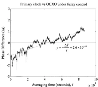
The performances of the OCXO under the fuzzy and the PD control are shown in Figs. 12 and 13, respectively. Over the ap-proximately 30-m baseline, the remote OCXO clock is auto-matically steered to approach synchronization with the primary clock. The accuracy of the remote OCXO clock can be improved from about 5 10 to 2.6 10 for averaging times of one
Fig. 10. Phase difference between free running OCXO and primary clock with linear-fit line.
Fig. 11. Phase difference between GPSDO and primary clock with linear-fit line.
Fig. 12. Phase difference between primary clock and remote clock under fuzzy control with linear-fit line.
Fig. 13. Phase difference between primary clock and remote clock under PD control with linear-fit line.
day. From these results, we demonstrate that the typical type of the fuzzy control and the PD control are suitable for frequency syntonization based on the carrier phase measurements.
V. CONCLUSION
In this paper, we propose a new scheme for frequency syn-tonization using the GPS carrier phase double differences. The scheme can achieve the traceability of frequency dissemination. The low-cost OCXO clock can be automatically steered to ob-tain the very high frequency accuracy and stability in the short term, as well as in the long term. In addition, we observed that the fuzzy controller and the PD controller are suitable for fre-quency syntonization based on the GPS carrier phase measure-ments. Experimental results show that our system is sound and cost-effective. The proposed architecture using low-cost GPS engines and inexpensive OCXO through PSTN or an Internet data link has been currently used to establish the frequency source for calibration laboratories and telecommunication net-works in Taiwan.
REFERENCES
[1] B. Hofmann-Wellenhof, H. Lichtenegger, and J. Collins, Global
Posi-tioning System: Theory and Practice, New York: Springer-Verlag, 1994.
[2] D. Wells, Gude to GPS Positioning: Canadian GPS Associates, 1996. [3] D. Drianko, H. Hellendoorn, and M. Reinfrank, An Introduction to Fuzzy
Control, New York: Springer-Verlag, 1992.
[4] G. F. Franklin, J. D. Powell, and A. Emami-Naeini, Feedback Control of
Dynamic Systems, 3rd ed. Reading, MA: Addison-Wesley, 1994. [5] J. A. Davis and J. M. Furlong, “Report on the study to determine the
suitability of GPS disciplined oscillators as time and frequency standards traceable to the UK national time scale UTC (NPL),” Centre for Time Metrology, Nat. Phys. Lab., Teddington, U.K., 1997.
[6] G. Petit and C. Thomas, “GPS frequency transfer using carrier-phase measurements,” in Proc. IEEE Freq. Contr. Symp., 1996, pp. 1151–1159. [7] K. Larson and J. Levine, “Time-transfer using GPS carrier phase methods,” in Proc. 29th Precise Time Time Interval Meet., Long Beach, CA, 1997.
[8] C. Bruyninx, P. Defraigne, J. M. Sleewaegen, and P. Paquet, “Frequency transfer using GPS: Comparative study of code and carrier phase anal-ysis results,” in Proc. 30th Precise Time Time Interval Meet., 1998. [9] D. Allan and M. Weiss, “Accurate time and frequency transfer using
common-view of a GPS satellite,” in Proc. IEEE Freq. Contr. Symp., 1998, pp. 334–356.
[10] Definitions and terminology for synchronization, Int. Telecommun. Union, Telecommun. Stand. Sector (ITU-T), G.810, Aug. 1996. [11] Timing characteristics of primary reference clocks, Int. Telecommun.
Union, Telecommun. Stand. Sector (ITU-T), G.811, Sept. 1997.
Kun-Yuan Tu was born in Taiwan, R.O.C., in
1966. He received the B.S. degree from the National Taiwan Institute of Technology, Taipei, in 1993 and the M.S. degree from National Taiwan University (NTU), Taipei, in 1996, in electrical engineering. He is currently pursuing the Ph.D. degree at the Department of Electrical Engineering, NTU.
He joined the Telecommunication Laboratories, Chunghwa Telecom Co., Ltd.,Yang-Mei, Taoyuan, Taiwan, in 1998, as an Assistant Researcher. His research interests include time and frequency applications via the global positioning system.
Fan-Ren Chang was born in Taiwan, R.O.C.,
in 1949. He received the B.S. and M.S. degrees from the National Chiao Tung University, Hsinchu, Taiwan, in 1972 and 1974, respectively, and the Ph.D. degree from the University of Houston, Houston, TX, in 1985, all in electrical engineering.
From 1976 to 1981, he was an Assistant Re-searcher at the Chung Shan Institute of Science and Technology, Lungtan Shiang, Taoyuan, Taiwan. He worked on missile and fire control systems projects. He joined the Department of Electrical Engineering, National Taiwan University, Taipei, in 1985 as an Associate Professor. Since 1990, he has been a Professor with the same department. His current research interests include the linear multivariable system, the generalized system, and applications of the global positioning system.
Chia-Shu Liao was born in Taiwan, R.O.C, in 1961.
He received the B.S. and M.S. degrees from National Central University, Jungli, Taoyuan, Taiwan, in 1983 and 1985, respectively, all in geophysics.
He joined the Telecommunication Laboratories, Chunghwa Telecom Co., Ltd., Lungtan Shiang, Taoyuan, in 1985 as an Assistant Research Scientist. Since 1995, he has been a Senior Researcher at the same laboratories. He currently serves as the Chairman for the time and frequency technical com-mittee of the Asia-Pacific Metrology Programme (APMP TCTF). His current research interests include network synchronization, time and frequency transfer, and precise time and frequency applications.
Li-Sheng Wang was born in Taiwan, R.O.C, in 1961.
He received the B.S. degree from the National Taiwan University (NTU), Taipei, in 1983 and the M.S. and Ph.D. degrees from the University of Maryland, Col-lege Park, in 1987 and 1990, respectively, all in elec-trical engineering.
From 1990 to 1991, he held a research and teaching position at the Department of Mathematics, Univer-sity of Maryland. Since 1991, he has been with the In-stitute of Applied Mechanics, NTU, where he is cur-rently a Professor. His research interests include non-linear systems theory, guidance and control, geometrical mechanics, robotics, and aerospace applications.
Dr. Wang currently serves as an Associate Editor for IEEE TRANSACTIONS ONAUTOMATICCONTROL.