Observation of reflection feedback induced the
formation of bright-dark pulse pairs in an
optically pumped semiconductor laser
C. H. Tsou,1 H. C. Liang,2 K. F. Huang,1 and Y. F. Chen1,3,*
1Department of Electrophysics, National Chiao Tung University, 1001 Ta-Hsueh Rd. Hsinchu 30010, Taiwan 2Institute of Optoelectronic Science, National Taiwan Ocean University, Keelung 20224, Taiwan 3Department of Electronics Engineering, National Chiao Tung University, 1001 Ta-Hsueh Rd. Hsinchu 30010,
Taiwan
Abstract: It is experimentally demonstrated that the tiny reflection feedback can lead the optically pumped semiconductor laser (OPSL) to be operated in a self-mod-locked state with a pulse train of bright-dark pulse pairs. A theoretical model based on the multiple reflections in a phase-locked multi-longitudinal-mode laser is developed to confirm the formation of bright-dark pulse pairs. The present finding can offer an important insight into the temporal dynamics in mode-locked OPSLs.
©2016 Optical Society of America
OCIS codes: (140.3538) Lasers, pulsed; (140.4050) Mode-locked lasers; (140.5960)
Semiconductor lasers; (140.7270) Vertical emitting lasers.
References and links
1. Y. Kivshar and B. Luther-Davies, “Dark optical solitons: physics and applications,” Phys. Rep. 298(2–3), 81– 197 (1998).
2. A. Hasegawa and F. Tappert, “Transmission of stationary nonlinear optical pulses in dispersive dielectric fibers. II. Normal dispersion,” Appl. Phys. Lett. 23(4), 171–172 (1973).
3. M. Kauer, J. R. A. Cleaver, J. J. Baumberg, and A. P. Heberle, “Femtosecond dynamics in semiconductor lasers: Dark pulse formation,” Appl. Phys. Lett. 72(13), 1626–1628 (1998).
4. J. Zimmermann, S. T. Cundiff, G. von Plessen, J. Feldmann, M. Arzberger, G. Bohm, M. C. Amann, and G. Abstreiter, “Dark pulse formation in a quantum-dot laser,” Appl. Phys. Lett. 79(1), 18–20 (2001).
5. M. Feng, K. L. Silverman, R. P. Mirin, and S. T. Cundiff, “Dark pulse quantum dot diode laser,” Opt. Express
18(13), 13385–13395 (2010).
6. H. Zhang, D. Y. Tang, L. M. Zhao, and X. Wu, “Dark pulse emission of a fiber laser,” Phys. Rev. A 80(4), 045803 (2009).
7. Y. Meng, S. Zhang, X. Li, H. Li, J. Du, and Y. Hao, “Bright-dark soliton pairs emission of a fiber laser,” Proc. Commun. Photon. Conf. Exhibit. 8307, 83071S (2011).
8. H. Y. Wang, W. C. Xu, W. J. Cao, L. Y. Wang, and J. L. Dong, “Experimental Observation of Bright Dark Pulse Emitting in an All Fiber Ring Cavity Laser,” Laser Phys. 22(1), 282–285 (2012).
9. X. Wang, P. Zhou, X. Wang, H. Xiao, and Z. Liu, “2 µm bright–dark pulses in Tm-doped fiber ring laser with net anomalous dispersion,” Appl. Phys. Express 7(2), 022704 (2014).
10. Q. Y. Ning, S. K. Wang, A. P. Luo, Z. B. Lin, Z. C. Luo, and W. C. Xu, “Bright–dark pulse pair in a figure-eight dispersion-managed passively mode-locked fiber laser,” IEEE Photonics J. 4(5), 1647–1652 (2012).
11. J. Gao, F. M. Hu, X. D. Huo, and P. Gao, “Bright-dark pair in passively mode-locked fiber laser based on graphene,” Laser Phys. 24(8), 085104 (2014).
12. B. Guo, Y. Yao, J. Tian, Y. Zhao, S. Liu, M. Li, and M. Quan, “Observation of bright-dark soliton pair in a mode-locked fiber laser with topological insulator,” IEEE Photon. Technol. Lett. 27(7), 701–704 (2015). 13. Y. Meng, S. Zhang, H. Li, J. Du, Y. Hao, and X. Li, “Bright-dark soliton pairs in a self-mode locking fiber
laser,” Opt. Eng. 51(6), 064302 (2012).
14. A. C. Tropper, H. D. Foreman, A. Garnache, K. G. Wilcox, and S. H. Hoogland, “Vertical-external-cavity semiconductor lasers,” J. Phys. D Appl. Phys. 37(9), R75–R85 (2004).
15. Y. F. Chen, Y. C. Lee, H. C. Liang, K. Y. Lin, K. W. Su, and K. F. Huang, “Femtosecond high-power
spontaneous mode-locked operation in vertical-external cavity surface-emitting laser with gigahertz oscillation,” Opt. Lett. 36(23), 4581–4583 (2011).
16. L. Kornaszewski, G. Maker, G. P. A. Malcolm, M. Butkus, E. U. Rafailov, and C. J. Hamilton, “SESAM-free mode-locked semiconductor disk laser,” Laser Photonics Rev. 6(6), L20–L23 (2012).
17. A. R. Albrecht, Y. Wang, M. Ghasemkhani, D. V. Seletskiy, J. G. Cederberg, and M. Sheik-Bahae, “Exploring ultrafast negative Kerr effect for mode-locking vertical external-cavity surface-emitting lasers,” Opt. Express
18. M. Gaafar, D. A. Nakdali, C. Möller, K. A. Fedorova, M. Wichmann, M. K. Shakfa, F. Zhang, A. Rahimi-Iman, E. U. Rafailov, and M. Koch, “Self-mode-locked quantum-dot vertical-external-cavity surface-emitting laser,” Opt. Lett. 39(15), 4623–4626 (2014).
19. H. C. Liang, C. H. Tsou, Y. C. Lee, K. F. Huang, and Y. F. Chen, “Observation of self-mode-locking assisted by high-order transverse modes in optically pumped semiconductor lasers,” Laser Phys. Lett. 11(10), 105803 (2014).
20. M. Gaafar, P. Richter, H. Keskin, C. Möller, M. Wichmann, W. Stolz, A. Rahimi-Iman, and M. Koch, “Self-mode-locking semiconductor disk laser,” Opt. Express 22(23), 28390–28399 (2014).
21. C. H. Tsou, H. C. Liang, C. P. Wen, K. W. Su, K. F. Huang, and Y. F. Chen, “Exploring the influence of high order transverse modes on the temporal dynamics in an optically pumped mode-locked semiconductor disk laser,” Opt. Express 23(12), 16339–16347 (2015).
22. R. M. Arkhipov, A. Amann, and A. G. Vladimirov, “Pulse repetition-frequency multiplication in a coupled cavity passively mode-locked semiconductor lasers,” Appl. Phys. B 118(4), 539–548 (2015).
23. L. Jaurigue, O. Nikiforov, E. Schöll, S. Breuer, and K. Lüdge, “Dynamics of a passively mode-locked
semiconductor laser subject to dual-cavity optical feedback,” Phys. Rev. E Stat. Nonlin. Soft Matter Phys. 93(2), 022205 (2016).
24. A. E. Siegman, Lasers (University Science Books, 1986), p. 1081.
25. Y. F. Chen, M. T. Chang, W. Z. Zhuang, K. W. Su, K. F. Huang, and H. C. Liang, “Generation of sub-terahertz repetition rates from a monolithic self-mode-locked laser coupled with an external Fabry-Perot cavity,” Laser Photonics Rev. 9(1), 91–97 (2015).
1. Introduction
Pulse operation has been widely studied and plays an important role in the fields of laser physics and laser engineering. Among various pulse lasers, mode-locked lasers are well-known light sources to generate pulses with the pulse duration on the order of picoseconds or femtoseconds. Generally, the mode-locked pulses are regarded as the bright pulse which means a short intensity peak beyond a continuous wave (CW) background. Intriguingly but rarely observed, the so-called dark pulse can be also observed in mode-locked lasers. In contrast to the bright pulse, a dark pulse is a rapid intensity dip in the intensity of a CW background [1]. Since the first theoretical prediction of dark nonlinear pulses by Hasegawa et al [2], the formation of dark pulses has been reported in various laser systems [3–6]. In the theoretical aspect, the nonlinear Schrödinger equation (NLSE) is usually employed to model the formation and propagation of the dark pulse in nonlinear media such as optical fibers [1]. Recently, the generation of bright-dark pulse pairs has attracted substantial interest in fiber lasers, where the bright-dark pulse pair means that bright and dark pulses can coexist in the pulse train. To date, bright-dark pulse pairs have been experimentally demonstrated in different fiber lasers [7–12], and the formation of bright-dark pulse in the fiber laser is usually analyzed by the coupled generalized Ginzburg-Landau equation [13].
Optically pumped semiconductor lasers (OPSLs) offer a unique combination of many desirable laser properties such as high output power, flexible emission wavelength, and nearly diffraction-limited beam quality [14]. In the last few years, the phenomena of self-mode-locking (SML) have been reported in OPSLs with different cavity configurations [15–21]. The SML operation means that no additional active or passive mode-locking elements (such as saturable absorbers) are used in the laser cavity except for the gain medium. In previous works [19,21], we observed that the OPSL displayed the SML feature with the co-existence of the TEM0,0 mode and the first high-order transverse mode. In the absence of high-order
transverse modes, the laser output was found to be in the CW operation. To obtain well-behaved bright pulses in the SML operation, the laser cavity was aligned to avoid any unwanted reflection. The riches of temporal states such as SML operation imply that OPSLs can be a promising platform to explore the temporal dynamics. Especially, the nonlinear dynamics of passively mode-locked semiconductor lasers with external feedback and coupled to the external passive cavity has been studied so far [22,23].
In this work, we first observe an intriguing phenomenon in an OPSL related to the formation of bright-dark pulse pairs. We find that the tiny reflection feedback can cause the OPSL to emit bright-dark pulse pairs in the SML operation. In the cavity configuration, we employ a concave-plano mirror as the output coupler (OC) to form a linear cavity. The
of the OC is quite low, experimental results reveal that it can significantly affect the temporal dynamics of the OPSL. We experimentally find that under the influence of the residual reflection, the phase locking between lasing longitudinal modes can be assisted to form bright-dark pulse pairs in the scale of round-trip time. Moreover, trains of bright-dark pulse pairs with different repetition rates can be obtained by adjusting the cavity length. We develop a theoretical model to consider the effect of multiple reflections in phase-locked multi-longitudinal modes. The numerical calculations are found to be agree very well with experimental results, which verifies that the origin of bright-dark pulse pairs comes from the influence of the reflection feedback on phase-locked multi-longitudinal modes. The present finding not only provides a practical route to achieve bright-dark pulse pairs in an OPSL, but also signifies that the reflection feedback may play an important role in the formation of bright-dark pulse pairs in other laser systems.
2. Cavity configuration and design of aperture size
The OPSL cavity consists of a semiconductor gain chip, a pump laser diode, and a concave-plano mirror. The gain chip and the pump laser diode were obtained from a commercial OPSL module (Coherent Inc.). The active region was a structure of multiple quantum wells to form a resonant periodic gain. The gain chip included a structure of distributed Bragg reflectors (DBRs) to act as the front mirror. The photoluminescence emission wavelength of the gain chip was approximately 1060 nm at room temperature. For effectively removing the heat from the gain structure, the gain chip was soldered with indium to chemical vapor deposition diamond heat spreader with DBR side down. The gain structure was antireflection coated at the wavelengths of 808 nm and 1060 nm. The radius of the 808 nm pump beam was approximately 320 μm. The concave-plano mirror was utilized as the OC with the radius of curvature of 800 mm. The OC had a partial reflection coating (R=98.5%) on the concave surface and an anti-reflection coating (R≈0.2%) on the plane surface.
O O θ (a) (b) ˆz ˆy ˆx Semiconductor Gain Medium Laser Diode Output Coupler Semiconductor Gain Medium Laser Diode Output Coupler
Fig. 1. Two cavity designs for exploring the influence of the reflection feedback: (a) the configuration in the absence of the reflection feedback. (b) the configuration with the existence of the reflection feedback.
Figure 1 depicts the schematic diagram of the OPSL, where the point O represents the center of the radius of curvature of the OC. As shown in Fig. 1(a), we aligned the optical axis to have a small angle (θ=0.38) with respect to the normal of the plane surface of the OC,
hence the laser emission did not propagate along the central axis of the OC. For the reason that the gain chip was not parallel to the plane side of the OC, the influence of the residual reflection from the plane surface of the OC could be completely avoided. In contrast to Fig. 1(a), Fig. 1(b) shows that the optical axis was set to coincide with the normal of the plane surface of the OC. When the laser emission emitted from the plane surface of the OC vertically, the residual reflection could cause the tiny reflection feedback. With these two cavity configurations, we can manipulate the influence of the residual reflection.
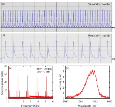
Wavelength (nm) 1060 1061 1062 1063 In te ns ity ( μ W) 0 1 2 3 4 5 6 Frequency (GHz) 0 1 2 3 4 5 6 Spe ct ra l pow er (dB m ) 0 20 40 60 80 0 5 ns/div (a) (c) RBW = 300 kHz (d) VBW = 3 kHz 0 1 ns/div (b) 50 mV/div 50 mV/div
Fig. 2. Experimental measurements in the SML operation without the reflection feedback: (a) the temporal trace with time span of 50 ns, (b) the temporal trace with time span of 10 ns, (c) the RF spectrum, and (d) the optical spectrum.
3. Influence of the reflection feedback on bright pulses
First of all, the cavity length was adjusted to be around 115 mm. With ABCD matrix, the cavity mode size on the gain chip was calculated to be 308 μm. For the reason that the radius of the pump beam was larger than the cavity mode size on the gain chip, the first high-order transverse mode was experimentally found to be excited at the pump power of 12.48 W. With the co-existence of TEM0,0 mode and the first high-order transverse mode, the OPSL can be
operated in the SML operation [19,21]. Figure 2 shows the overall observations for the laser operated at a pump power of 14.4 W with the cavity configuration depicted in Fig. 1(a). The temporal behavior of the laser output was detected by a high-speed InGaAs photodetector (Electro-Optics Technology Inc. ET-3500 with rise time 35 ps), whose output signal was connected to a digital oscilloscope (Lecroy 820Zi-A) with 20 GHz electrical bandwidth and a sampling interval of 25 ps. The maximum linear CW power of the detector was 10 mW, and the laser power coupled into the detector was approximately 7.5 mW. Figure 2(a) shows the temporal trace with the time span of 50 ns demonstrating the mode-locked pulses. The pulse trains with nearly-zero CW background indicates the realization of mode locking. In Fig. 2(b), the unapparent pulse tail implied that there were slight amplitude fluctuations of longitudinal modes with time variation [24]. Figure 2(c) illustrates the peak values of the harmonics of the longitudinal mode spacing Δ =fL 1.3 GHz in the RF spectrum, and the signal to noise was
approximately 60 dB, regarding as larger than the standard value of well-behaved SML operation. In the meantime, there were two beat peaks which accompanied the harmonics of the longitudinal mode spacing in the RF spectrum. The beat frequency was measured to be 161 MHz which was corresponded to the transverse mode spacing ΔfT. The peak values of beat frequencies were less than 20 dB. The appearance of the beat peaks at the frequencies of
L T
f = ⋅Δ ± Δu f f with u = 1, 2, 3, 4 in the RF spectrum distinctly revealed the existence of the first high-order transverse mode. A Fourier optical spectrum analyzer (Advantest Q8347), which was constructed with a Michelson interferometer, was employed to monitor the spectral
maximum (FWHM) in the optical spectrum was found to be as wide as 0.84 nm. It could be seen that there was not any periodic modulation in the optical spectrum, hence the temporal state was in the SML operation without the influence of residual reflection. Because the longitudinal mode spacing was nearly equal to the resolution of the spectrum analyzer, it could be seen slight modulation on the envelope of the optical spectrum. According to the optical spectrum, it was also verified that influence of residual reflection was completely avoided by employing the cavity configuration shown in Fig. 1(a).
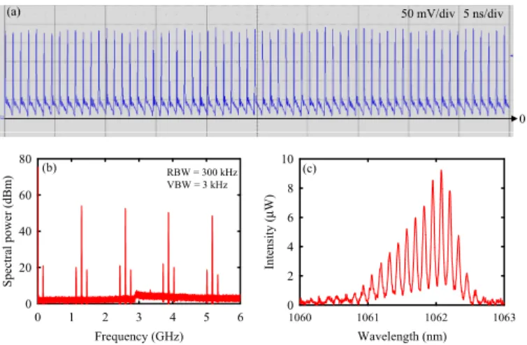
Wavelength (nm) 1060 1061 1062 1063 In tensity ( μ W) 0 2 4 6 8 10 Frequency (GHz) 0 1 2 3 4 5 6 Sp ect ra l p ow er ( dBm ) 0 20 40 60 80 0 5 ns/div (a) (b) RBW = 300 kHz (c) VBW = 3 kHz 50 mV/div
Fig. 3. Experimental measurements in the SML operation with the reflection feedback: (a) the temporal trace, (b) the RF spectrum, and (c) the optical spectrum.
Next, the cavity length was still set to be 115 mm, but we utilized the cavity configuration plotted in Fig. 1(b). The performance of SML was observed for the laser operated at the same pump power. Referring to Fig. 3(a), the bright pulse train was still obtained, but the pulse shape was not as symmetric as the temporal trace depicted in Fig. 2(a). As shown in Fig. 3(b), all frequency peaks in the RF spectrum were measured at the same frequencies plotted in Fig. 2(c). However, the signal to noise was found to be 54 dB, considering smaller than the results shown in Fig. 2(c). The experimental measurements revealed that the cavity configuration illustrated in Fig. 1(b) was not appropriate for the bright pulses in the SML operation. In Fig. 3(c), it could be seen that there was the distinctly periodic modulation in the optical spectrum. The spacing between two periodic peaks was measured to be 0.12 nm which was corresponded to the optical length of the OC of 4.7 mm. Consequently, the experimental results indicate that the tiny reflection feedback is a disadvantage for generating well-behaved bright pulses in the SML operation.
4. The formation of bright-dark pulse pairs
In the following section, we considered that only the fundamental transverse mode was excited in the laser cavity. The cavity length was set to be around 200 mm, hence the cavity mode size on the gain chip was calculated to be approximately 342 μm. The pump threshold for high-order transverse modes could be increased significantly because the cavity mode size on the gain chip was larger than the radius of the pump beam [19]. For the pump power ranging from the lasing threshold to the maximum pump power of 22.08 W, the laser output was experimentally found to display the fundamental transverse mode. Without the existence of high-order transverse modes, the laser cannot emit bright pulses in the SML operation [19,21].
Wavelength (nm) 1060 1061 1062 1063 Intensity ( μ W) 0 10 20 30 40 Frequency (GHz) 0 1 2 3 4 5 Spe ct ra l pow er (dB m ) 0 10 20 30 40 50 0 1 ns/div (a) (b) RBW = 300 kHz (c) VBW = 3 kHz 50 mV/div
Fig. 4. Experimental results for the laser in the CW operation without the reflection feedback: (a) the temporal trace, (b) the RF spectrum, and (c) the optical spectrum.
Figure 4 illustrates overall performances for the laser operated in the CW operation at a pump power of 14.4 W with the cavity configuration plotted in Fig. 1(a). The temporal trace did not exhibit any obvious oscillations, as shown in Fig. 4(a). Referring to Fig. 4(b), there were several frequency peaks corresponded to the harmonics of the longitudinal modes spacing Δ =fL 765 MHz in the RF spectrum, and the peak values were less than 20 dB,
considering much smaller than standard value of mode-locked lasers. As seen in Fig. 4(c), the optical spectrum was found to be centered at 1061.86 nm, and the full width at half maximum (FWHM) was found to be as narrow as 0.04 nm. Note that there was no any periodic modulation in the optical spectrum. Therefore, the results exhibited that the laser was operated in the CW operation when only the TEM0,0 mode was excited and the influence of the residual
reflection was avoided.
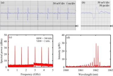
However, under the influence of the residual reflection, the observations of temporal dynamics was beyond expectations. Figure 5 depicts the experimental measurements for the laser operated at a pump power of 14.4 W with the cavity configuration plotted in Fig. 1(b). As shown in Fig. 5(a), the temporal trace exhibited a distinctly pulse train of bright-dark pulse pairs. It could be seen that a bright pulse followed a dark pulse in the single pulse of bright-dark pulse pairs. The depth of the bright-dark pulse was approximately equal to the intensity of the bright pulse in the CW background. Figure 5(b) illustrates the single bright-dark pulse pair, where the pulse widths of bright and dark pulses were measured of 18 ps. The pulse duration did not changed with varying the pump power in the range of 11.52-15.36 W. In Fig. 5(c), there were several frequency peaks in the RF spectrum corresponded to the harmonics of the longitudinal mode spacing Δ =fL 765 MHz, and the peak values were approximately 30 dBm. Without any additional active or passive mode-locking element, the results revealed that the emission of bright-dark pulse pairs was in the SML operation. As a result of the nonzero CW background, the signal to noise of bright-dark pulse pairs was smaller than the standard value of bright pulses in mode-locked lasers. Referring to Fig. 5(d), it could be seen that there was the obviously periodic modulation in the optical spectrum. The spacing between two periodic peaks was measured to be 0.12 nm which was corresponded to the optical length of the OC of 4.7 mm. The time-bandwidth product was calculated to be 0.575. The results revealed that under the influence of the residual reflection, the multi-longitudinal modes could be phase-locked to form bright-dark pulse pairs in the scale of round-trip time. Comparing the results in Figs. 4 and 5, it signifies that the reflection feedback is necessary for the formation of bright-dark pulse pairs in an OPSL.
Wavelength (nm) 1060 1061 1062 1063 In te nsi ty ( μ W) 0 10 20 30 40 Frequency (GHz) 0 1 2 3 4 5 Sp ec tr al p ow er (d B m ) 0 10 20 30 40 50 0 1 ns/div (a) (c) RBW = 300 kHz (d) VBW = 3 kHz 50 ps/div (b) 0 50 mV/div 50 mV/div
Fig. 5. Experimental observations for overall performances of bright-dark pulse pairs: (a) the temporal trace, (b) the RF spectrum, and (c) the optical spectrum.
Furthermore, we demonstrate the temporal dynamics of bright-dark pulse pairs with varying the pump power. Figure 6 illustrate the experimental results for temporal traces measured at four different pump powers. For the pump power ranging from the lasing threshold to 11.52 W, bright-dark pulse pairs were observed with apparent noise on the CW background, as shown in Fig. 6(a) for the result measured at a pump power of 10.56 W. With increasing the pump power, the appropriate pump power for generating bright-dark pulse pairs was experimentally found to be in the range of 11.52-15.36 W. Referring to Fig. 6(b), the temporal trace manifested bright-dark pulse pairs with indistinct noise on the CW background at a pump power of 14.4 W. However, it was found that the temporal state was changed for the pump power greater than 15.36 W. Figures 6(c) and 6(d) depict bright-dark pulse pairs measured at pump powers of 18.24 and 22.08 W, respectively. As the pump power was increased, the depth of dark pulse and the intensity of bright pulse both became less and less. It could be seen that the bright-dark pulse pairs began to transform into the CW operation when the pump power was higher than 15.36 W.
2 ns/div 0 0 0 0 2 ns/div 2 ns/div 2 ns/div (a) (b) (c) (d) 50 mV/div 50 mV/div 50 mV/div 50 mV/div
Fig. 6. Bright-dark pulse pairs at different pump powers: (a) Pin = 10.56 W, (b) Pin = 14.4 W,
(c) Pin = 18.24 W, and (d) Pin = 22.08 W.
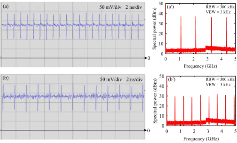
The temporal traces of bright-dark pulse pairs with different repetition rates can be obtained by adjusting the cavity length. Figures 7(a) and 7(b) illustrate the temporal trace and the RF spectrum of bright-dark pulse pairs at the cavity length of 135 mm. As seen in Fig. 7(a), it could be seen that the distinct bright-dark pulse pairs were generated successfully. In Fig. 7(aʹ), there were four frequency peaks in the RF spectrum corresponded to the harmonics of the longitudinal mode spacing Δ =fL 1.11GHz, and the peak values were approximately 38 dBm. With increasing the cavity length, Figs. 7(b) and 7(bʹ) depict the temporal trace and the RF spectrum at the cavity length of 250 mm. Referring to Fig. 7(bʹ), the frequency peaks were
corresponded to the harmonics of the longitudinal mode spacingΔ =fL 600 MHz. It is worth
to note that the pulse structures in Figs. 6 and 7 are the same as the pulse shape shown in Fig. 5(b). The results verified that bright-dark pulse pairs could be obtained not only at a specific cavity length. Frequency (GHz) 0 1 2 3 4 5 Spect ral power ( dBm) 0 10 20 30 40 50 Frequency (GHz) 0 1 2 3 4 5 Spec tral po w er (dBm) 0 10 20 30 40 50 (aʹ) (bʹ) RBW = 300 kHz VBW = 3 kHz RBW = 300 kHz VBW = 3 kHz (a) (b) 0 0 2 ns/div 2 ns/div 50 mV/div 50 mV/div
Fig. 7. Experimental measurements of bright-dark pulse pairs with different repetition rates: (a) the temporal trace and (aʹ) the RF spectrum at the cavity length of 135 mm. (b) the temporal trace and (bʹ) the RF spectrum at the cavity length of 250 mm.
5. Theoretical analysis of bright-dark pulse pairs
The formation of the bright-dark pulse pairs in a mode-locked laser could be understood more clearly with the numerical reconstruction of the temporal trace. The theoretical model of SML operation with external Fabry-Perot etalon effect has been manifested in the spectral domain in terms of the Lorentzian function [25]. However, in the following analysis, we developed a theoretical model to consider the effect of multiple reflections in a phase-locked multi-longitudinal-mode laser. The normalized complex electric field for the single-spectral-band mode-locked laser with amplitude coefficients following a binomial distribution and equal phases can be expressed as
( )
0 2 2 2 , 2 n i t N i t N T n N N n N e t C e ω π ψ + =− = ⋅
(1)where ω0 is the angular frequency for the central longitudinal mode, T is the resonator
round-trip time, n is the longitudinal mode index, and 2N + 1 is the number of longitudinal oscillating modes. According to experimental results, the residual reflection from the plane surface of the OC led the lasing beam to multiply reflect when the cavity configuration shown in Fig. 1(b) was employed. Considering the multiple reflections, the electric field after each reflection is a mode-locked pulse train with the relatively delayed time corresponded to the optical path of the OC is given by
( )
0 2 2 2 , 2 t m i t N i n N T m N n N n N e t ω C e π τ ψ + ⋅− ⋅ =− = ⋅
(2)where m is the index of multiple reflections, τ is the delayed time caused from each reflection. Therefore, the total output a superposition of multiple mode-locked pulse trains with the amplitude coefficient of each pulse train:
( )
( )
(
)
0 0 2 2 2 0 0 2 0 2 , t m i t M M N i n N T m m N m n N m m n N N M i t m m e t A t A C e e A cos t m T τ ω π ω ψ π τ − ⋅ ⋅ + = = =− = Ψ = ⋅ = ⋅ ⋅ = ⋅ ⋅ − ⋅
(3)where M + 1 is the number of reflections, and Am is the amplitude coefficient of each pulse train. Based on Eq. (3), we numerically reconstructed the oscilloscope trace of bright-dark pulse pairs shown in Fig. 5(a). According to the experimental condition, the parameters in used in the fitting were as follows: T =1.3 ns , τ =31ps , Am = +1 1.5⋅δm,0 , N =45,
39
M = , and ω =0 1.78 PHz. Figure 8 illustrates the numerical pulse train for the best fit to
the experimental result shown in Fig. 5(a). It can be seen that the numerical result agrees very well with the experimental measurement. The good agreement validates that the origin of bright-dark pulse pairs comes from the reflection feedback in phase-locked multi-longitudinal modes. Time (ns) -5 -4 -3 -2 -1 0 1 2 3 4 5 In ten sity ( a.u .) 0 5 10 15 20 25
Fig. 8. The numerically reconstructed pulse train.
4. Conclusions
In summary, we have experimentally demonstrated that the phase locking between lasing longitudinal modes in an OPSL can be assisted by either the first high-order transverse mode or the residual reflection from the outer side of the OC. Experimental results revealed that when the influence of the residual reflection was avoided, bright pulses in the continuous SML operation could be achieved with the co-existence of the TEM0,0 mode and the first
high-order transverse mode. Nevertheless, it was experimentally found that under the influence of the residual reflection, distinct bright-dark pulse pairs at the scale of round-trip time could be observed in the absence of high-order transverse modes. Furthermore, trains of bright-dark pulse pairs with different repetition rates have been generated successfully by adjusting the cavity length. A theoretical model has been developed to consider the effect of multiple reflections in phase-locked multi-longitudinal modes. Although the experimental measurements did not reveal the phase locking between longitudinal modes, the numerical reconstruction of bright-dark pulse pairs indicated that the reflection feedback could force the phase locking. The good agreement between numerical calculations and experimental results validates that the reflection feedback in a phase-locked multi-longitudinal-mode laser gives rise to the formation of bright-dark pulse pairs.
Acknowledgments
The authors acknowledge the Ministry of Science and Technology of Taiwan for the financial support of this research under Contract No. MOST 103-2112-M-009-0016-MY3.