Polarized backlight based on selective total
internal reflection at microgrooves
Ko-Wei Chien, Han-Ping D. Shieh, and Hugo Cornelissen
A polarized backlight for LCD illumination is designed and fabricated in which s-polarized light is extracted owing to selective total internal reflection at microstructures in the anisotropic layer. From the measurement, the contrast ratio in normal viewing direction can be as high as 64. Luminous uniformity of higher than 80% is achieved for polarized backlights. Furthermore, 1.6 gain in efficiency is obtained aiming for high-efficiency LCD illumination. © 2004 Optical Society of America
OCIS codes: 240.5420, 260.1440, 160.3710, 150.2950.
1. Introduction
In a conventional backlight for LCD illumination, over 50% of the energy is absorbed in the back polar-izer while polarized light is produced. Polarized backlights are more efficient than conventional back-lights because they recycle light of undesired polar-ized direction. In addition, the back polarizer can be left out to further reduce the thickness of LCD mod-ules. In a previous design,1 a polarized backlight
used microstructures at the Brewster angle to pro-duce unipolarized light. However, the polarization efficiency is strongly dependent on the incident an-gles of light. In addition, a stack of multilayered thin films共alternating layers of materials of high and low refraction indices兲 was designed to match a quarter-wave optical thickness in each layer, so that Brewster condition was satisfied to produce a specific polarized state of light.2 However, the tolerances in
the incident angle and the wavelength are very lim-ited.
Polarization backlight based on selective total in-ternal reflection共TIR兲 at the interface of microstruc-tures was proposed.3 As schematically shown in
Fig. 1, a birefringent layer with microgrooves was filled with an isotropic index-matching layer
adher-ing to the lightguide substrate. The birefringent layer has an ordinary index of refraction no, which is
closely matched to the refraction index of index-matching layer and an extraordinary refraction index
ne. The approach to separate the polarized light was aimed to extract one polarization state of light by selective TIR at the microstructure interface. The extraordinary refractive index ne of the birefringent
layer should be significantly larger than the refrac-tive index ncof the index-matching layer so that
suf-ficiently small critical angle at the interface can be achieved. In contrast, the critical angle at the inter-face is not present for the orthogonally polarized light. Light therefore remains in its propagating di-rection at the interface of the microstructures.
2. Theory
The electric field amplitude E can be decomposed either parallel or perpendicular to the incident plane. The transmission coefficient t and reflection coeffi-cient r depend on the incident polarization direction and are given by the Fresnel equations for dielectric media:4,5 TE共s polarization兲: t⫽Et E ⫽ 2 cosi cosi⫹ 共n2⫺ sin2i兲1兾2 , TM共 p polarization兲: t⫽Et E ⫽ 2n cosi n2cosi⫹ 共n 2 ⫺ sin2 i兲1兾2 ,
K.-W. Chien and H.-P. D. Shieh共[email protected]兲 are with the Institute of Electro-Optical Engineering, National Chiao Tung University, Hsinchu, Taiwan 30010. H. Cornelissen is with Philips Research Laboratories WY63, Professor Holstlaan 4, 5656AA Eindhoven, The Netherlands.
Received 30 March 2004; revised manuscript received 11 May 2004; accepted 17 May 2004.
0003-6935兾04兾244672-05$15.00兾0 © 2004 Optical Society of America
TE共s polarization兲: r⫽Er E ⫽ cosi⫺ 共n2⫺ sin2i兲1兾2 cosi⫹ 共n 2⫺ sin2 i兲1兾2 , TM共 p polarization兲: r⫽Er E ⫽ n2cosi⫺ 共n 2⫺ sin2 i兲1兾2 n2cos i⫹ 共n2⫺ sin2i兲1兾2 ,
in which n is the relative refractive index共n2兾n1兲.
The transmittance T and reflectance R are related to the transmission and reflection coefficients by4,5
T⫽ n共cos t兾cos i兲t2and R⫽ r2.
The above-mentioned Fresnel equations show a po-larization dependence of the transmittance and the reflectance at the interface. As shown in Fig. 1, for an uniaxial birefringent film, p-polarized light en-counters the low ordinary refractive index no and
s-polarized light encounters a weighted average of no
and ne. The polarization separation can be achieved
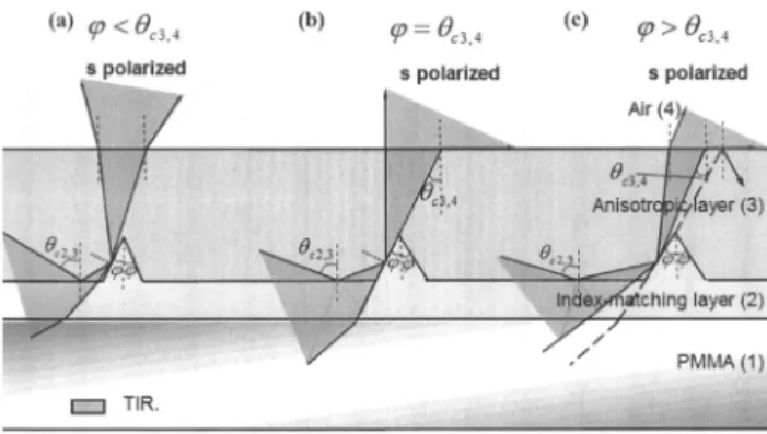
at the interface by a complete reflection of one polar-ization direction, whereas the orthogonal polariza-tion direcpolariza-tion is refracted toward the anisotropic film. Only s-polarized light encounters TIR, because a crit-ical anglec⫽ sin⫺1共no兾neffective,s-polarized兲 exits at the interface, where it is extracted from the lightguide. The angular distributions of outcoupling s-polarized light depend on the top angle of microgrooves in the anisotropic layer. Figure 2 demonstrates the distri-butions of s-polarized light if half of the top angle is smaller, equal, or exceeding the critical anglec3,4of the anisotropic layer with respect to air.6
c2,3
de-picts the critical angle of the anisotropic layer with respect to the index-matching layer. For equal to or exceedingc3,4, light can be refracted at a maxi-mum external outcoupling angle of 90° if the incident angle is no more thanc3,4at the interface between the anisotropic layer and air. Light undergoes TIR and is trapped in the lightguide if the incident angle is larger thanc3,4. For smaller than c3,4, light
can be refracted at an external outcoupling angle of less than 90°.
3. Simulation
To consider contrast ratio, angular distributions, and efficiency in more detail, we analyzed several issues. An optical simulation and analysis program, Ad-vanced System Analysis Program, was used to sim-ulate the polarized light by Monte Carlo ray tracing in birefringent material. Uniaxial birefringent ma-terials, stretched polyethylene terephthalate 共PET兲 and polyethylene naphthalate 共PEN兲, were used as an anisotropic layer, which was adhered to a polym-ethyl methacrylate 共PMMA兲 substrate by an index-matching glue. Furthermore, in order to analyze both s-polarized and p-polarized light, we built a po-larizer on the top of polarized backlight model.
s-polarized light was analyzed when the direction of
polarizer was parallel to the direction of micro-grooves. p-polarized light was analyzed when the direction of polarizer was perpendicular to the direc-tion of microgrooves. The refractive indices of PMMA and anisotropic layer are listed as
Fig. 3. Illustration of contrast ratio at a different refractive index of index-matching layer. Contrast ratio achieves maximum at perfectly matched refractive index n⫽ 1.53 for PET foil, whereas
n⫽ 1.56 for PEN foil.
Fig. 1. Schematics of polarized backlight. Birefringent layer with microgrooves filled with index-matching layer was aimed to extract the s-polarized light at the interface. Additionally,
p-polarized light was trapped in the polymethyl methacrylate
共PMMA兲 lightguide to be recycled.
Fig. 2. Illustration of outcoupled s-polarized light due to selective TIR at the interface for different half-top angles relative to the critical anglec3,4of the anisotropic layer with respect to air: 共a兲
共i兲 PET: nPMMA ⫽ 1.49; no,PET ⫽ 1.53;
ne,PET⫽ 1.71,
共ii兲 PEN: nPMMA ⫽ 1.49; no,PEN ⫽ 1.56;
ne,PEN⫽ 1.86.
Contrast ratio of the polarized backlight model was analyzed at different refractive indices of the index-matching layer. Contrast ratio is defined as the ra-tio of intensity of s-polarized to p-polarized light. For PEN foil, contrast ratio achieves 190 at perfectly matched n⫽ 1.56, whereas 160 is achieved at n ⫽ 1.53 for PET foil, shown in Fig. 3.
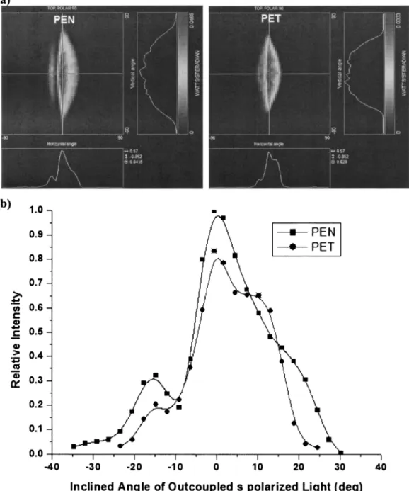
As shown in Fig. 4, we demonstrated the angular distributions and inclined angular cross sections of outcoupling s-polarized light at perfectly matched
in-dices for PEN and PET foils, respectively. The top angle of grooves is 50°. The angular profiles are plotted as a function of inclination angles, which range from⫺90° to 90°, with respect to the normal viewing direction. Most of the s-polarized light is distributed between the inclination angle of⫺30° and 30° for PEN foil and⫺25° and 25° for PET.
4. Experiments
Stretched PEN foils were adhered to a PMMA sub-strate by UV curing of the index-matching glue. Mi-crogrooves were directly cut into PEN foils by diamond turning. The top angle and the depth of the grooves were 50° and 56.5m, respectively. The pitch of the grooves was 200 m. The polarized
Fig. 4. 共a兲 Angular distributions and 共b兲 Inclined angular cross-sections of outcoupled s-polarized light at perfectly matched index for PEN and PET foils, respectively.
backlight module was side illuminated by a cold-cathode fluorescent lamp. Angular distributions of emitting light from the backlight module were mea-sured with an EZcontrast 160 measuring system. To determine the contrast ratio of s-polarized light to
p-polarized light, we placed a polarizer between the
backlight and the detector, so that the transmission axis of polarizer could be rotated to be parallel or perpendicular to the extraordinary axis of the bire-fringent layer. Figures 5共a兲 and 5共b兲 demonstrated the angular distributions of s-polarized and
p-polarized light, respectively, where the angular
dis-tributions were plotted as a function of azimuth angle ⬘ ranging from 0° to 360°, and the inclination angle
Fig. 5. Measured angular profiles of共a兲 s-polarized light and 共b兲 p-polarized light and 共c兲 contrast ratio of s-polarized to p-polarized light.
Fig. 6. For PEN foil adhered on the substrate of PMMA, luminous intensity versus position from light source. Squares, circles, and triangles illustrate luminous intensity of s-polarized light with no reflectors, diffuse end reflector only, and both back and end reflec-tors, respectively.
Fig. 7. Measurement set up of flux by共a兲 clear PMMA and 共b兲 polarized backlight with both back and end reflectors.
, ranging from 0° to 80°. Peak intensity is 456 cd兾m2for the s-polarized light and 96 cd兾m2for the
p-polarized light. Most s-polarized light is distrib-uted between the inclination angle of⫺30° and 30°.
p-polarized light is distributed in large inclination
angles. Figure 5共c兲 depicts the contrast ratio of
s-polarized light to p-polarized light. The peak value of contrast ratio of s-polarized to p-polarized light achieves 64.
From the measured results, it is clear that
s-polarized light significantly dominates the emitting
light of the polarized backlight module. However, because the scattering light occurred at the surfaces of the microgrooves, the contrast ratio of s-polarized to p-polarized light is not yet sufficiently high. We expect that the contrast ratio can be further en-hanced when the surface smoothness of the micro-grooves is improved. Additionally, luminous intensity was sequentially measured from a position of 8 mm away from the light source共i.e., close to the light source兲 to a position of 52 mm away from the light source 共i.e., far away from light source兲. As shown in Fig. 6, curves with squares, circles, and triangles illustrate the luminous intensity of the
s-polarized light with no reflectors, diffuse end
reflec-tor only, and both back and end reflecreflec-tors, respec-tively. With both back reflector and end reflector, the maximum and the minimum of luminous inten-sity are 625 and 500 lm兾m2, respectively.
Unifor-mity can therefore reach 80%.
To evaluate the gain of efficiency of polarized back-light, we measured the efficiency by following proce-dures shown in Fig. 7. Total input flux was measured at the end of a clear PMMA. Theoreti-cally, all of the rays were TIR in the lightguide until being transmitted through the end. Therefore total input flux was 2.12 lm. Then, fluxes of s-polarized and p-polarized light were sequentially measured to be 1.56 and 0.39 lm, respectively, from the outcoupled plane. Input fluxes of s-polarized and p-polarized light were assumed to be equally 0.975 lm关共1.56 lm ⫹ 0.39 lm兲兾2 ⫽ 0.975 lm兴. Outcoupled energy was to-tally 92% of input flux. The rest 8% flux was lost in reflectors and lamp. Therefore, an efficiency gain factor of 1.6 was achieved for s-polarized light共gain factor⫽ 1.56 lm兾0.975 lm ⫽ 1.6兲.
5. Discussion
Compared with PET foil, stretched PEN foil demon-strates a higher contrast ratio of s-polarized to
p-polarized light owing to large difference of
refrac-tive indices共⌬n ⫽ ne,PEN⫺ no,PEN⫽ 0.3, ⌬n ⫽ ne,PET
⫺ no,PET⫽ 0.18兲. Additionally, PEN demonstrates a
wider angular distribution than does PET owing to the large birefringence. Most of the s-polarized light is distributed between the inclination angle of⫺30° and 30° for PEN foil and⫺25° and 25° for PET. A smaller critical angle is presented at the interface of grooves for PEN, thus broadening the angular distri-bution on the outcoupled plane. In simulation,
when the ordinary refractive index no⫽ 1.56 of PEN foil is perfectly matched to the refractive index of glue layer, the flux of the p-polarized light is expected to achieve a minimum, whereas for PET foil is perfectly matched at no⫽ 1.53. Therefore the contrast ratio of s-polarized light to p-polarized light achieves a maximum. However, the mismatched indices be-tween the anisotropic foil and the glue layer cause an increasing amount of p-polarized light owing to Fresnel surface reflection at the interface,7 but not
obviously for s-polarized light; thus, the contrast ratio degrades. To retain a contrast ratio of higher than 80, one can mismatch the refractive index of the glue layer to within⫾0.015 for the PEN foil and ⫾0.01 for the PET foil. Therefore the PEN foil provides higher tolerances in mismatched refractive indices com-pared with the PET foil. However, from the mea-sured results, the contrast ratio is lower than our designed value because of the presence of dust and air bubbles during the process of micromachining the anisotropic foil and the index-matching glue. The contrast ratio can be further increased by a more-controllable fabrication process.
6. Conclusion
A polarized backlight based on selective TIR at the interface of microgrooves was demonstrated. An outcoupling of s-polarized light occurs in a cone of ⫾30° around the surface normal, whereas p-polarized stray light occurs in large inclination angles. Con-trast ratio in normal viewing direction can be as high as 64. Additionally, polarized backlights with end and back reflectors provide luminous uniformity of higher than 80%. Furthermore, a 1.6 gain in effi-ciency is obtained, aiming for high-effieffi-ciency LCD illumination.
References
1. M. F. Weber, “Retroreflecting sheet polarizer,” in Society for
Information Display International Symposium Digest, J.
Mor-reale, ed. 共Society for Information Display, San Jose, Calif., 1992兲, pp. 427–429.
2. Z. Pang and L. Li, “Novel high efficiency polarizing backlighting system with a polarizing beam splitter,” in Society for
Informa-tion Display InternaInforma-tional Symposium Digest, J. Morreale, ed.
共Society for Information Display, San Jose, Calif., 1999兲, pp. 916 –919.
3. H. Jagt, H. Cornelissen, D. Broer, and C. Bastiaansen, “Micro-structured polymeric linearly polarized emitting light-guide for LCD illumination,” in Society for Information Display
International Symposium Digest, J. Morreale, ed.共Society for
Information Display, San Jose, Calif., 2002兲, pp. 1236–1239. 4. E. Hecht, Optics, 2nd ed. 共Addison-Wesley, Reading, Mass.,
1987兲, p. 84.
5. F. J. Pedrotti and L. S. Pedrotti, Introduction to Optics, 2nd ed. 共Prentice Hall, London, 1993兲, p. 38.
6. H. Jagt, Polymeric Polarisation Optics for Energy Efficient
Liq-uid Crystal Display Illumination共University Press Facilities,
Eindhoven, The Netherlands, 2001兲, p. 114.
7. G. R. Fowles, Introduction to Modern Optics, 2nd ed.共Holt, Rineheart & Winston, New York, 1975兲, p. 168.