IEEE TRANSACTIONS ON ANTENNAS AND PROPAGATION, VOL. 55, NO. 3, MARCH 2007 1009
REFERENCES
[1] L. C. Godara, Handbook of Antennas in Wireless Communication. Boca Raton, FL: CRC Press, 2002.
[2] M. Ali, S. S. Stuchly, and K. Caputa, “A wide-band dual meander-sleeve antenna,” J. Electromagn. Waves and Applicat., vol. 10, no. 9, pp. 1223–1236, 1996.
[3] C.-W. P. Huang, A. Z. Elsherbeni, J. J. Chen, and C. E. Smith, “FDTD characterization of meander line antennas for RF and wireless com-munications,” Progress in Electromagn. Res., PIER 24, pp. 185–199, 1999.
[4] M. G. Douglas, M. Okoniewski, and M. A. Stuchly, “A planar diversity antenna for handheld PCS devices,” IEEE Trans. Veh. Tech., vol. 47, no. 3, pp. 747–754, 1998.
[5] T. Taga, “Analysis for mean effective gain of mobile antennas in land mobile radio environments,” IEEE Trans. Veh. Tech., vol. 39, pp. 117–131, May 1990.
[6] K. Kalliola et al., “Angular power distribution and mean effective gain of mobile antenna in different propagation environments,” IEEE Trans. Veh. Tech., vol. 51, no. 5, pp. 823–838, 2002.
[7] K. Rosengren and P.-S. Kildal, “Study of distribution of modes and plane waves in reverberation chamber for characterization of antennas in multipath environment,” Microw. Opt. Tech. Lett., vol. 30, no. 20, pp. 386–391, Sept. 2001.
[8] A. Khaleghi, J. C. Bolomey, and A. Azoulay, “On the statistics of rever-beration chambers and applications for wireless antenna test,” in Proc. IEEE Int. Symp. on Antennas and Propagation (AP-S), Albuquerque, NM, Jul. 2006, pp. 3561–3564.
[9] P. J. Massey and K. R. Boyle, “Controlling the effects of feed cable in small antenna measurements,” in IEE, ICAP 2003, April 2003. [10] A. Khaleghi, “Diversity techniques with parallel dipole antennas:
ra-diation pattern analysis,” Progress In Electromagn. Res., PIER 64, pp. 23–42, 2006.
[11] M. Ali, G. J. Hayes, H. Huan-Sheng, and R. A. Sadler, “Design of a multiband internal antenna for third generation mobile phone hand-sets,” IEEE Trans. Antennas Propag., vol. 51, no. 7, pp. 1452–1461, Jul. 2003.
A Reconfigurable Quadri-Polarization Diversity Aperture-Coupled Patch Antenna
Yi-Fan Wu, Chun-Hsien Wu, Don-Yen Lai, and Fu-Chiarng Chen
Abstract—We present a novel reconfigurable quadri-polarization diver-sity aperture-coupled patch antenna which can provide four polarization states. By controlling the dc bias voltage of the pin-diodes on the feeding network, we can reconfigure the proposed antenna to provide a pair of or-thogonal linear polarizations and a pair of oror-thogonal circular polariza-tions. Numerical and experimental results validate our design. This novel antenna provides potential polarization diversity features for wireless local area networks and multiple-input multiple-output systems.
Index Terms—Aperture-coupled patch antenna, dual-polarization, pin-diode, polarization-diversity, quadri-polarization, reconfigurable antenna.
I. INTRODUCTION
Polarization diversity is drawing a lot of attention in modern wire-less communication systems due to its several advantages. First, polar-ization diversity is effective to avoid the fading loss caused by multi-path effects [1]. Second, polarization diversity can be utilized to realize frequency reuse due to its useful polarization modulation scheme [2]. This property has been applied in active read/write microwave tagging systems [2]. In [3], the authors use two orthogonal dipole antennas to achieve the purpose of polarization diversity for Wireless Local Area Network (WLAN) applications. There are also other ways to imple-ment the polarization diversity antenna by exciting dual orthogonal modes in a single patch. In [4], a patch antenna uses dual orthogonal H-slots to excite a pair of orthogonal modes in the patch.
In recent years, the pin-diodes provide versatility for polarization diversity applications. We can reconfigure the antenna to operate in different excitation modes by controlling the on/off states of the pin diodes in the antenna structures [1], [2], [5]–[9]. In [6], a reconfig-urable microstrip patch antenna for switchable polarizations is pro-posed. The geometry consists of a corner-truncated square patch and two pairs of opposite corners with four pin diodes as conductors. By properly controlling the pin diodesONorOFF, it can generate linear polarizations, or a left-handed circular polarization, or a right-handed circular polarization. For the first time, we propose a novel quadri-po-larization diversity aperture coupling patch antenna with aperture cou-pling and dual-feed structure technique to provide a pair of orthogonal linear polarizations and a pair of orthogonal circular polarizations. The proposed antenna has not only quadri-polarization diversity but also a wide axial-ratio bandwidth. The geometry of the antenna is described in Section II. Details of the simulation and experimental results are presented in Section III. In conclusion, this novel reconfigurable patch antenna is a potential candidate for future polarization diversity ap-plications in the WLAN and multiple-input multiple-output (MIMO) communication systems.
Manuscript received February 28, 2006; revised June 16, 2006. This work was supported by the National Science Council, Taiwan, R.O.C., under Grants NSC 95-2221-E-009-044-MY3, NSC 95-2752-E-002-009-PAE, and NSC 94-2219-E-009-015.
The authors are with the Department of Communication Engineering, National Chiao Tung University, Hsinchu 300, Taiwan, R.O.C. (e-mail: [email protected]).
Digital Object Identifier 10.1109/TAP.2006.889947 0018-926X/$25.00 © 2007 IEEE
1010 IEEE TRANSACTIONS ON ANTENNAS AND PROPAGATION, VOL. 55, NO. 3, MARCH 2007
Fig. 1. Geometry of the quadric-polarization antenna. (a) Top view of the pro-posed antenna (W p = 42:5 mm, W s = 1:15 mm Ls = 22:5 mm, Lo = 6:5 mm, W f = 1:55 mm, Le = 2:25 mm). (b) Side view of the proposed antenna.
II. ANTENNADESIGN
The geometry of the proposed antenna is shown in Fig. 1. The an-tenna consists of four rectangular apertures on the ground plane fed by four microstrip feeding lines, a branch line coupler, 8 pin-diodes, and a square patch. The antenna is designed to operate at 2.45GHz for the WLAN applications. The antenna was made by using a low-priced FR-4 substrate of thickness 0.8 mm with a relative permittivity 4.4. Fig. 1(b) shows that the four apertures on the ground plane and feeding network under the ground plane were printed on the different side of the same dielectric substrate. The substrate of the radiating patch and the substrate of the ground plane are also separated by an air layer of thicknessh = 1 mm (the supporting posts not shown in the figure). As shown in Fig. 1(a), the antenna structure comes with the following layout parameters: the width of the square patch isW p, the width of the slot isW s, the length of the slot is Ls, the length from the open end of the feed line to the center of the slot is Lo, the distance from the edge of the patch to the slot isLe, and width of the feed line is W f. The entire size of the proposed polarization diversity antenna is 120 mm2 110 mm.
The proposed antenna can provide quadri-polarization states by switching the eight pin-diodes embedded in the feeding network of the antenna shown in Fig. 1(a). To properly supply a dc bias for the pin-diodes, we need to design the RF choke inductors with a very high RF impedance, the dc block capacitors with a very low impedance at the RF frequency, and the quarter-wavelength microstrip line
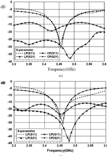
Fig. 2. Simulated and measured S-parameters data: (a) Simulation. (b) Measurement.
which is via-grounded to realize the dc ground. A quarter-wavelength microstrip line is utilized on the FR-4 substrate to work as the RF choke inductor. The dc block capacitors and the RF choke inductors can separate the dc signal and the RF signal in the feeding network efficiently such that unwanted interference can be prevented. The forward-bias of the pin-diode is VF = 0:95 Volt. The pin-diode model number is Infineon BAR50-02L. A dc block capacitor with C = 100 pF with a very low impedance at the RF frequency is used. The design considerations for the quadri-polarization are described in detail in the following subsections.
A. A Pair of Orthogonal Linear-Polarizations Design
By controlling the dc bias voltage of the pin-diodes D5, D6, D7, and D8 properly, the antenna can provide a pair of orthogonal linear-po-larizations. By switching on the above four pin-diodes, we can create a signal path from the right side feeding line of port-1 excitation to upper slot. Then the upper slot couples the signal to the patch that can generate a linear polarization state. In this condition, we design the half-wave-lengthac to achieve an infinite input impedance from a to c. Under this condition, the input power can be fed to right-upper slot totally. At the same time, the other pin-diodes D1, D2, D3, and D4 are switched off to block the possible excitation of unwanted modes from the branch line coupler feeding. On the other hand, because the geometry of proposed antenna is symmetrical, the signal path from the left side feeding line of port-2 excitation can generate another orthogonal linear polarization
IEEE TRANSACTIONS ON ANTENNAS AND PROPAGATION, VOL. 55, NO. 3, MARCH 2007 1011
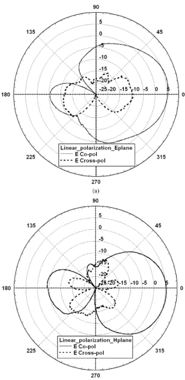
Fig. 3. Measured linear polarization radiation patterns of the proposed antenna. (a) E-plane. (b) H-Plane.
state. Therefore, this antenna can produce a pair of orthogonal linear polarizations.
B. A Pair of Orthogonal Circular-Polarization Design
By controlling the dc bias voltage of the pin-diodes D1, D2, D3, and D4 properly, the antenna can provide a pair of orthogonal circular-po-larizations. By switching on the above four pin-diodes, we can create a signal path from the branch line coupler feeding line of port-1 exci-tation to two lower slots. Then the two lower slots couple the signal
Fig. 4. Measured circular polarization radiation pattern of the proposed antenna.
to the patch that can generate a circular polarization state. Owing to a quarter phase difference made by the branch line coupler, the circular polarization is LHCP. We design a half-wavelengthab as to achieve an infinite input impedance froma to b. Under this condition, the input power can be fed to both lower slots totally. It is important that we must design a good performance branch line coupler which has equal power output at the directional port and the coupled port to achieve a per-fect circular polarization in the designed frequency band. At the same time, the pin-diodes D5, D6, D7, and D8 are switched off to block the possible excitation of unwanted modes from outside feeding line. On the other hand, the geometry of proposed antenna is symmetrical so the signal path from port-2 excitation can generate another orthogonal circular polarization state which is RHCP. Therefore, this antenna can produce a pair of orthogonal circular polarizations.
III. SIMULATION ANDEXPERIMENT
This proposed aperture coupling patch antenna is simulated by a 3D-full wave MOM solver, IE3D. Similar to [5], we utilized the equiv-alent lengths of metal tapes to represent the conducting pin-diodes. When the pin-diodes are in theOFFstate, they are removed from the simulation. The return loss and isolation for the linear polarization modes and circular polarization modes are simulated and measured. The simulated results and the measured results are shown in Fig. 2. In Fig. 2(b), the measured 10-dB impedance bandwidth for 2.45 GHz band is about 3.67% for the LP mode. The 10-dB impedance bandwidth is about 3.88% for the CP mode. Satisfactory agreement between sim-ulation and measurement is observed.
Fig. 3 shows the measured gains of the co-polarization and cross-po-larization of the E-plane and H-plane for the LP mode. The measured CP radiation pattern of the proposed antenna is showed in Fig. 4. We found that the obtained antenna gain is about 2 dBi received by a linear isotropic antenna; hence, the total gain of the proposed antenna is the measured gain plus 3 dBi for the absolute gain of the antenna refer-enced to a circularly polarized isotropic antenna [10]. Therefore, in the CP mode, the gain of the proposed antenna is about 5 dBi for a polar-ization-pure CP signal. Moreover, the fluctuation of the CP radiation
1012 IEEE TRANSACTIONS ON ANTENNAS AND PROPAGATION, VOL. 55, NO. 3, MARCH 2007
pattern curve is very small around 0 degrees; therefore it demonstrates the proposed antenna is an excellent CP antenna.
IV. CONCLUSION
A novel reconfigurable quardri-polarization diversity antenna is pro-posed for multipolarization diversity applications. Using pin-diodes on the feeding network paths, the antenna can be operated either in dual-linear polarizations state or in dual-circular polarizations state ac-cording to different dc bias voltages of the pin-diodes. Our experi-mental results show that the design antenna has good performance in S-parameters, gain and axial ratio. Our novel quadri-polarization diver-sity antenna can be a good candidate for future polarization diverdiver-sity applications in the WLAN and MIMO communications systems.
REFERENCES
[1] M. K. Fries, M. Grani, and R. Vahldieck, “A reconfigurable slot antenna with switchable polarization,” IEEE Microw. Wireless Compon. Lett., vol. 13, pp. 490–492, Nov. 2003.
[2] F. Yang and Y. Rahmat-Samii, “A reconfigurable patch antenna using switchable slots for circular polarization diversity,” IEEE Microw. Wireless Compon. Lett., vol. 12, pp. 96–98, Mar. 2002.
[3] S.-T. Fang, “A novel polarization diversity antenna for WLAN appli-cation,” in Proc. IEEE Antennas and Propagation Society Symp., Jul. 2000, vol. 1, pp. 282–285.
[4] K.-L. Wong and T.-W. Chiou, “Finite ground plane effects on broad-band dual polarized patch antenna properties,” IEEE Trans. Antennas Propag., vol. 51, no. 4, Apr. 2003.
[5] F. Yang and Y. Rahmat-Samii, “Patch antenna with switchable slot (PASS): Dual-frequency operation,” Microw. Opt. Technol. Lett., vol. 31, no. 3, pp. 165–168, Nov. 2001.
[6] Y. J. Sung, T. U. Jang, and Y.-S. Kim, “A reconfigurable microstrip antenna for switchable polarization,” IEEE Microw. Wireless Compon. Lett., vol. 14, no. 11, pp. 534–536, Nov. 2004.
[7] M. Boti, L. Dussopt, and J.-M. Laheurte, “Circular polarized antenna with switchable polarization sense,” Electron. Lett., vol. 36, no. 18, 2000.
[8] F. Yang and Y. Rahmat-Samii, “Switchable dual-band circularly po-larized patch antenna with single feed,” Electron. Lett., vol. 37, no. 16, 2001.
[9] N. Jin, F. Yang, and Y. Rahmat-Samii, “A novel reconfigurable patch antenna with both frequency and polarization diversities for wireless communications,” in Proc. IEEE Antennas and Propagation Society Symp., Jun. 2004, vol. 2, pp. 1796–1799.
[10] B. Y. Toh, R. Cahill, and V. F. Fusco, “Understanding and measuring circular polarization,” IEEE Trans. Education, vol. 46, no. 3, pp. 313–318, Aug. 2003.