國 立 交 通 大 學
電信工程研究所
碩 士 論 文
上行多點協調式系統之傳收機設計
Transceiver Design for Uplink Coordinated
Multipoint Systems
研 究 生:梁曉婷
Student: Hsiao-Ting Liang
指導教授:李大嵩 博士
Advisor: Dr. Ta-Sung Lee
上行多點協調式系統之傳收機設計
Transceiver Design for Uplink Coordinated Multipoint
Systems
研 究 生:梁曉婷
Student: Hsiao-Ting Liang
指導教授:李大嵩博士 Advisor: Dr. Ta-Sung Lee
國立交通大學
電信工程研究所
碩士論文
A Thesis
Submitted to Institute of Communications Engineering
College of Electrical and Computer Engineering
National Chiao Tung University
in Partial Fulfillment of the Requirements
for the Degree of
Master of Science
in
Communications Engineering
September 2012
Hsinchu, Taiwan, Republic of China
上行多點協調式系統之傳收機設計
學生:梁曉婷
指導教授:李大嵩 博士
Chinese Abstract
國立交通大學電信工程研究所碩士班
摘要
為了達到下世代蜂巢式無線系統更進一步的性能要求,多種典型的技術在這 種受限於干擾的環境下被發展出來。多點協調(coordinated multipoint; CoMP)傳輸 與接收技術以及多輸入多輸出(multiple input multiple output; MIMO)技術為其中兩 種對抗干擾之關鍵性技術。在本篇論文中,吾人於集中式上行傳輸多點協調系統 中提出兩種多天線、多資料串流之疊代式傳收機設計。第一種傳收機設計引入干 擾校齊(interference alignment; IA)的概念,可達到干擾校齊以及干擾抑制的作用。 第二種傳收機設計則是藉由最小化有效通道矩陣之條件數以及最大化有效通道矩 陣之奇異值以強化有效通道之條件。根據模擬結果,吾人所提出之方法具有優秀 的收斂特性。再者,在少數疊代運算內就可達到較好的速率總和、較為公平的結 果,並且對於疊代運算中的初始值較為穩定。Transceiver Design for Uplink Coordinated
Multipoint Systems
Student: Hsiao-Ting Liang
Advisor: Dr. Ta-Sung Lee
English Abstract
Institute of Communications Engineering
National Chiao Tung University
Abstract
To achieve advanced performance requirements for the next generation cellular wireless systems, several classic techniques have been developed under such interference limited environments. Coordinated multipoint (CoMP) transmission and reception and multiple input multiple output (MIMO) systems are two key techniques to overcome the effect caused by interference. In this thesis, two iterative centralized uplink CoMP transceiver schemes are proposed where multiple antennas and multiple transmit layers are assumed. The fist one incorporates the idea of a new emerging technique, interference alignment (IA) which can align and then mitigate the interference. The second proposed method is developed to enhance the effective channel condition by minimizing the condition number and maximizing the singular values of the effective channel matrix. According to the simulation results, the proposed methods can provide superior convergence behavior. The results also show that they achieve rather good sum-rate performance, provide robustness to the initial values in the iterative procedures, and lead to much fairer results, within few iterations.
Acknowledgement
First, I would like to express my sincere gratitude to my advisor, Dr. Ta-Sung Lee, for his guidance and inspiring discussions. His positive and conscientious attitude in research has benefited me in my study as well. Also, I am really grateful to all my friends and the members in the Communication System Design and Signal Processing (CSDSP) Lab for their constant encouragement and help. Finally, I would like to thank my family for their tremendous love, kind words, and support.
Table of Contents
Chinese Abstract ... i
English Abstract ... ii
Table of Contents ... iv
List of Figures ... vi
List of Tables ... viii
Acronym Glossary ... ix
Notations ... x
Chapter 1 Introduction ... 1
Chapter 2 System Model ... 4
2.1 Uplink Coordinated Multipoint (CoMP) System Model ... 5
2.2 Transceiver Structure and Associated Achievable Sum-Rate in UL CoMP ... 8
2.3 Interference Alignment in K-user Interference Channel ... 14
2.4 Summary ... 18
Chapter 3 Interference Alignment (IA) Aided Transceiver Design
... 20
3.1 Motivation ... 21
3.2 Incorporation of IA in UL CoMP ... 22
3.3 Proposed IA Aided Transceiver in UL CoMP ... 27
3.4 Computer Simulations ... 33
Chapter 4 Channel Condition Enhanced Transceiver Design ... 39
4.1 Motivation ... 40
4.2 Proposed Channel Condition Enhanced Transceiver ... 41
4.3 Complexity Analysis of Proposed UL CoMP Transceivers ... 45
4.4 Computer Simulations ... 47
4.5 Summary ... 54
Chapter 5 Conclusions and Future Works ... 56
List of Figures
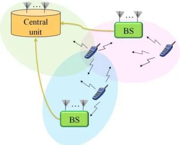
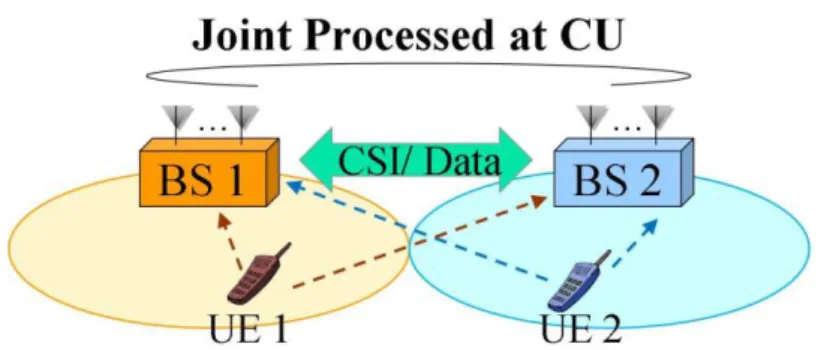
Figure 2-1: Centralized CoMP scheme controlled by a central unit (CU) ... 6
Figure 2-2: Scenario 1 (homogeneous network with intra-site CoMP)[1] ... 6
Figure 2-3: Scenario 2 (homogeneous network with high Tx power RRHs)[1] ... 7
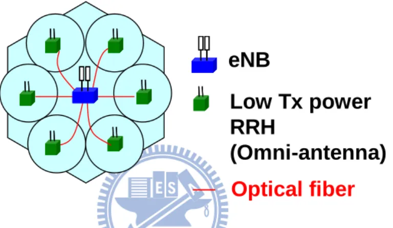
Figure 2-4: Scenario 3/4 (heterogeneous network with low power RRHs within the macrocell coverage where the RRHs have different/the same cell IDs as the macro cell)[1] ... 7
Figure 2-5: Centralized UL CoMP with full cooperation ... 8
Figure 2-6: Illustration of the MMSE transceiver proposed in [10] ... 9
Figure 2-7: Rate convergence behavior of MMSE transceiver [10] with K = 3, u = 1 ... 9
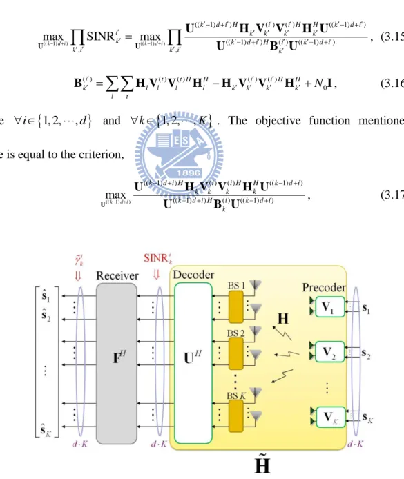
Figure 2-8: Illustration of UL CoMP sytem model ... 10
Figure 2-9: Illustration of UL CoMP closed loop communication system ... 12
Figure 2-10: Illustration of DL CoMP closed loop communication system ... 13
Figure 2-11: Illustration of IA in K-user interference channel ... 16
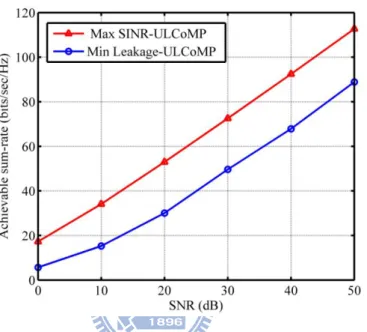
Figure 3-1: Sum-rate performance of Min Leakage-UL CoMP and Max SINR-UL CoMP with K=3, Mt=4, Mr=4, d=2, and no. of iterations=20 ... 26
Figure 3-2: Illustration of centralized UL CoMP transceiver scheme, SINRik, and ki ... 28
Figure 3-3: Flow chart of the proposed IA aided UL CoMP scheme ... 29
Figure 3-4: Rate convergence behavior of Min Leakage-UL CoMP, Max SINR-UL CoMP, and IA aided UL CoMP with Mt=4, Mr=2, K=3, d=2, and SNR = 10/30 (dB) .. 35
Figure 3-5: Rate convergence behavior of Min Leakage-UL CoMP, Max SINR-UL CoMP, and IA aided UL CoMP with Mt=4, Mr=4, K=3, d=3, and SNR = 10/30 (dB) .. 35
and IA aided UL CoMP with Mt=4, Mr=2, K=3, and d=2... 37
Figure 3-7: Sum-rate performance of Min Leakage-UL CoMP, Max SINR-UL CoMP,
and IA aided UL CoMP with Mt=4, Mr=4, K=3, and d=3... 37
Figure 4-1: Rate convergence behavior of IA aided UL CoMP, Channel condition
enhanced UL CoMP, and MMSE UL CoMP with Mt=4, Mr=2, K=3, d=2, and SNR =
20/30 (dB) ... 49
Figure 4-2: Rate convergence behavior of IA aided UL CoMP, Channel condition
enhanced UL CoMP, and MMSE UL CoMP with Mt=4, Mr=4, K=3, d=3, and SNR =
20/30 (dB) ... 49
Figure 4-3: Sum-rate performance of IA aided UL CoMP, Channel condition enhanced
UL CoMP, and MMSE UL CoMP with Mt=4, Mr=2, K=3, d=2, and no. of iterations=10
... 51
Figure 4-4: Sum-rate performance of IA aided UL CoMP, Channel condition enhanced
UL CoMP, and MMSE UL CoMP with Mt=4, Mr=4, K=3, d=3, and no. of iterations=10
... 51
Figure 4-5: Comparison of sensitivity to the initial value in the iterative procedure
between IA aided UL CoMP, Channel condition enhanced UL CoMP, and MMSE UL CoMP with Mt=4, Mr=2, K=3, and d=2 ... 53
Figure 4-6: Fairness between different users of IA aided UL CoMP, Channel condition
enhanced UL CoMP, and MMSE UL CoMP with Mt=4, Mr=2, K=3, and d=2 ... 54
Figure 5-1: Rate convergence behavior of IA aided UL CoMP, Channel condition
enhanced UL CoMP, and Advanced UL CoMP with Mt=4, Mr=2, K=3, d=2, and SNR =
20/30 (dB) ... 59
Figure 5-2: Rate convergence behavior of IA aided UL CoMP, Channel condition
enhanced UL CoMP, and Advanced UL CoMP with Mt=4, Mr=4, K=3, d=3, and SNR =
List of Tables
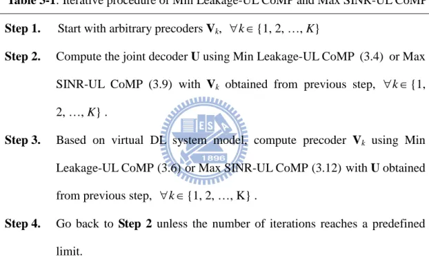
Table 2-1: Iterative procedure of Max SINR-IA and Min Leakage-IA ... 17 Table 3-1: Iterative procedure of Min Leakage-UL CoMP and Max SINR-UL CoMP 25 Table 3-2: Iterative procedure for the proposed IA aided UL CoMP transceiver design
... 33
Table 3-3: Simulation parameters ... 34 Table 4-1: Iterative procedure for the proposed channel condition enhanced transceiver
... 45
Table 4-2: Complexity comparison between different UL CoMP transceiver schemes 46 Table 4-3: Simulation parameters ... 47
Acronym Glossary
3GPP third generation partnership project
BC broadcast channel
BS base station
CoMP coordinated multipoint
CSI channel state information
CU central unit
DL downlink
DoF degrees of freedom
IA interference alignment
ICI inter cell interference
LTE-A long term evolution-advanced
MAC multiple access channel
MIMO multiple input multiple output
MMSE minimum mean square error
RRH remote radio head
SINR signal to interference and noise ratio
SNR signal to noise ratio
UE user equipment
Notations
K number of cells in the cooperation group
u number of UEs in each cell
t
M number of transmit antennas
r
M number of receive antennas
i k
s transmitted signal vector of the ith UE in the kth cell
i k
V precoder matrix of the ith UE in the kth cell
,
i k l
H channel between the kth BS and the ith UE in cell l
V collective precoder matrix
U decoder matrix
H collective channel matrix
F receiver matrix
T
d number of total transmit data streams
M
I identity matrix of size M×M
diag block diagonal matrix staking operator
T X transpose operator H X Hermitian operator 1 X inverse operation
E{} expectation operator
tr( ) trace operator
det( ) determinant operator
[x ]H (i) ith element of row vector x H
( )i
X the ith column of matrix X
{ }X ij matrix consists of the ith column to jth column of matrix X
Chapter 1
Introduction
The increasing demand for wireless equipments stimulates the evolution of existing mobile wireless communication systems to achieve higher data rates and more reliable link quality. Furthermore, due to the concern for scarcity of spectrum, unity frequency reuse is adopted in the next generation wireless communication system which would cause severe inter-cell interference (ICI). To meet performance requirements under such strict environments, advanced techniques have been developed such as coordinated multipoint (CoMP) transmission and reception and multiple input multiple output (MIMO) systems. These two techniques are provided as key solutions to alleviate the impact caused by ICI in the 4G mobile cellular standards, e.g. 3GPP LTE-Advanced [1].
CoMP is a technique that utilizes the cooperation between points in some cooperation group to coordinate the transmission/reception which is controlled by a central unit (CU) for the purpose of ICI alleviation and quality enhancement. CoMP has been adopted in practical cellular systems as a tool to improve cell coverage and cell edge throughput. In practice, CoMP can be classified by the capability of backhauling into full cooperation CoMP and partial cooperation CoMP [2]-[3]. Exchange of full information including full channel state information (CSI) and full data information is
allowed in full cooperation CoMP with less backhaul constraints. Centralized CoMP which can provide joint transmission or reception is one of the examples [4]-[5]. On the other hand, partial cooperation exchanges partial data and CSI. For this type of CoMP, distributed CoMP and coordinated scheduling are two typical approaches [2], [5].
MIMO exploits the spatial degrees of freedom provided by multiple antennas to offer improved system capacity and/or diversity for better link quality. It has become a promising technique in most existing communication standards. A great deal of research works have been done on the applications of MIMO in cellular systems. Using MIMO in a multi-user system inevitably increases the interference level for each user, so there is a need to develop methods for mitigating the inter-user interference [6].
Due to the potential for system performance improvement, centralized CoMP is considered as our research platform, where the CU jointly processes the received signals from all the BSs with full information exchange. Based on this structure, there is a common assumption that user equipment (UE) is equipped with a single antenna owing to cost, hardware, and size constraints. Thanks to the evolution of technology, multiple antennas are now available at UE in practical cellular network. Hence, centralized CoMP with multiple transmit and multiple receive antennas (MIMO) has attracted a lot of attention, and there are abundant researches that focus on the problem with a single transmit data stream (single transmit layer) [7]. However, the case with multiple transmit layers in centralized CoMP has not been widely studied. Therefore, to further improve communication efficiency, two transceiver schemes in centralized CoMP with multiple antennas and multiple transmit layers are developed in this thesis, and the study is focus on the uplink case due to no resource-consuming CSI feedback is needed.
Each of our two proposed algorithms includes precoders, a joint decoder, and a linear MMSE receiver, and is iterative in nature. In each iteration, two stage calculations are involved: 1) to calculate the joint decoder based on given precoders and 2) to compute the precoders based on a given decoder. The fist proposed transceiver scheme, called“IA aided UL CoMP”, incorporates the idea of a new emerging technique, interference alignment (IA). IA has recently developed for the X-channel and K-user interference channel as a capacity approaching technique [8]-[9]. The basic idea of IA is to align or compress interference into some limited subspace so the interference can be separated from the desired signal with sufficient degrees of freedom (DoF). The second proposed transceiver scheme, called “Channel condition enhanced UL CoMP”, is developed to enhance the effective channel condition by minimizing the condition number and maximizing the singular values of the effective channel matrix. UL-DL duality is also exploited in the second proposed method. All the simulation results show that both of the proposed approaches achieve superior system performance.
The thesis is organized as follows. The mathematical system model of centralized UL CoMP, the definition of achievable sum-rate, and the introduction of IA in K-user interference channel are illustrated in Chapter 2. In Chapter 3, the basic idea and the derivation of the proposed IA aided UL CoMP are illustrated. The proposed Channel condition enhanced UL CoMP is developed in Chapter 4. In the same chapter, complexity analysis and numerical evaluations of the two proposed methods are also provided. Finally, summary of our works and several potential future works are given in Chapter 5.
Chapter 2
System Model
The exponential growth of mobile data traffic and the demands of better link quality trigger the evolution of existing mobile wireless communication systems. To achieve the higher requirement of spectrum efficiency in next generation wireless systems, e.g., 3GPP LTE-Advanced, some typical communication schemes are adopted such as unity frequency reuses and multiuser transmission scheme, and that leads to an interference limited environment. Coordinated multipoint (CoMP) transmission and reception and multiple input multiple output (MIMO) systems are two key techniques proposed to overcome the effect caused by interference. In this thesis, we consider uplink CoMP (UL CoMP) assisted with multiple antennas as our system model, and two associated transceiver schemes are proposed, among which one incorporates the idea of interference alignment (IA), a recently emerged interference mitigation criterion.
In section 2.1, the classification of CoMP systems will be presented, and then we address the UL CoMP scheme adopted in this thesis. According to the considered UL CoMP scheme, the mathematical system model of multicell multiuser MIMO system and the transceiver design are introduced in section 2.2. Besides, we describe the performance metrics in terms of achievable sum-rate employing linear MMSE receiver.
Interference alignment has recently emerged as a generalized multi-user MIMO technique for the X-channel and K-user interference channel scenarios. Its superior performance of interference mitigation has been proven, and it will be incorporated into one of our transceiver design. The basic idea of IA in K-user interference channel is presented in section 2.3.
2.1 Uplink Coordinated Multipoint (CoMP)
System Model
In modern cellular communication systems, user equipment (UE) in the cell-edge region can sustain superior interference which will cause serious degradation of link quality. To cope with the issues caused by interference and further improve the system efficiency, coordinated multipoint (CoMP) transmission and reception are developed. The main idea is to utilize the cooperation between points (BSs or RRHs) in some cooperation group to operate joint transmission/reception and interference mitigation/avoidance, so better cell coverage and cell edge throughput could thus be achieved. The benefits provided by CoMP have been evaluated, and CoMP is adopted in some cellular networks, e.g., LTE-Advanced as a key technique. In practice, the cooperation in CoMP is restricted due to restricted latency and limited backhauling, and this leads to different CoMP schemes, with either full cooperation or partial cooperation [2]-[3]. In this thesis, a centralized UL CoMP with full cooperation is considered.
CoMP with full cooperation exchanges information including full channel side information (CSI) and full data information. Centralized CoMP with joint transmission /reception is a typical full cooperation approach which is controlled by a central unit (CU) that could be any point in the cooperation set as depicted in Figure 2-1 [4]-[5]; it is applicable to scenarios with less backhaul constraints such as that provided in
LTE-Advanced standard. In LTE-Advanced, scenario 1 is the homogeneous network aiming for intrasite multipoint coordination where no backhaul connection is needed, as illustrated in Figure 2-2. Scenario 2/3/4 is the homogeneous network with remote radio heads (RRHs) where the connection between coordinated points is provided by optical fiber which supports small latency and ample bandwidth, as illustrated in Figure 2-3 and Figure 2-4 [1], [5]. On the other hand, partial cooperation exchanges partial data and CSI. Distributed CoMP and coordinated scheduling are two approaches of partial cooperation [2], [5]. According to the potential for system performance improvement, we focus on centralized UL CoMP in this thesis.
Figure 2-1: Centralized CoMP scheme controlled by a central unit (CU)
eNB
Coordination area
High Tx power RRH
Assume high Tx power RRH as same as eNB
Optical fiber
Figure 2-3: Scenario 2 (homogeneous network with high Tx power RRHs)[1]
Low Tx power
RRH
(Omni-antenna)
eNB
Optical fiber
Figure 2-4: Scenario 3/4 (heterogeneous network with low power RRHs within the
macrocell coverage where the RRHs have different/the same cell IDs as the macro cell)[1]
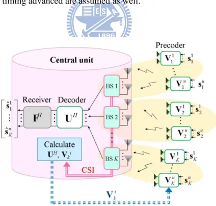
Centralized UL CoMP is a scheme that the transmitted signal from a particular user is received by multiple points in the cooperation set, and then due to full cooperation, the received signal from multiple points are joint processed at CU as illustrated in Figure 2-5. For the purpose of reasonable implementation complexity, linear processing is considered in this thesis. Due to the acceptable complexity and comparatively better tolerance to noise, linear MMSE receiver is adopted. In our work, multiple antennas are at both transmit and receive sides, and multiple transmit layers is assumed. We consider the structure that the transmitted signal vector of each UE is processed by its own linear precoder before transmission, and then with full BS
cooperation, the CU joint processes the received signal from all the BSs by linear decoder and linear MMSE receiver, successively.
Figure 2-5: Centralized UL CoMP with full cooperation
2.2 Transceiver Structure and Associated
Achievable Sum-Rate in UL CoMP
In this section, the mathematical system model of centralized UL CoMP involving multicell multiuser MIMO infrastructure is introduced; the basic structure of the associated transceiver design in this thesis is also presented in detail. Sum-rate performance is a major performance index in CoMP systems; the achievable sum-rate of centralized UL CoMP system equipped with linear MMSE receiver will be demonstrated.
Based on the structure of centralized UL CoMP, a typical minimum sum mean square error (MMSE) transceiver depicted in Figure 2-6 has been proposed in [10]. The
precoders V and the linear MMSE receiver F are calculated iteratively based on ij
MMSE criterion. However, it exhibits a poor convergence behavior as illustrated in
Figure 2-7, where the number of transmit layers, transmit antennas, and receive
antennas are 2, 4, and 2, respectively. For more efficient communication schemes, two transceiver designs are proposed in this thesis. Based on the property of the MMSE
receiver, a well-conditioned effective channel (consists of V and F) is formed when ij
the iterative process converges. According to this property, we introduce a joint decoder
U at CU that provides additional dimensions to facilitate the formation of a
well-conditioned effective channel as depicted in Figure 2-8, which is equivalent to accelerating the rate of convergence.
Figure 2-6: Illustration of the MMSE transceiver proposed in [10]
The considered uplink CoMP system involves K BSs (K cells), each equipped with
Mr antennas. There are u UEs within the coverage of a BS. Each UE has Mt transmit
antennas. The transmitted signal vector of the ith UE in kth cell is i dk 1
k s (E
k i i H k k ds s I ) where dk is called the number of layers and is processed by the
precoder matrix i Mt dk
k
V before transmission as illustrated in Figure 2-8. Here we
denote the channel matrix between the ith UE in lth cell and the kth BS as
, r t M M i k l
H , the total transmit signal dimension of lth cell as u×dl, the total transmit
signal dimension of the system as
1 K T l l d u d
, precoder matrix at lth cell as Vl =diag{Vl1, ,V }lu M ut d ul
, and the transmitted signal vector of lth cell as sl =
[(s )1l T (s )2l T,…,(s )ul T]T udl 1
. The received signal at the kth BS can be described as
Figure 2-8: Illustration of UL CoMP sytem model
, 1 K k k l l l k l
y H V s n , (2.1)where , Mr M ut
k l
H is the channel matrix between the kth BS and all UEs in lth cell,
and Mr 1
k
n is the noise vector with distribution CN
, 0
r
M
N
0 I . Denote the
precoded signal vector as xik V s . The transmit power is assumed to be restricted to k ki i P, i.e. tr(V Vki ki H) P. With full cooperation between BSs (centralized CoMP), the CU
collects the received signal from all K BSs as follows:
UL_CoMP
y HVs n , (2.2)
where H M Kr M uKt is the collective channel matrix,
UL_CoMP 1 2, , T T T T K y y y y M Kr 1 , V = diag{ V1 ,…, VK } t T M uKd , 1 2, , T 1 T d T T T K s s s s , and 1 1 2, , r T M K T T T K
n n n n . With full BS cooperation, uplink CoMP is transformed
into an equivalent multiple access channel (MAC)-like system [4]. The CU processes the received signal as follows:
UL_CoMP H H y U HVs U n Hs n, (2.3) UL_CoMP ˆ H H s F Hs F n, (2.4)
where UH dT(MrK)and FH dTdT are decoder matrix and linear MMSE receiver
matrix; ˆs is the estimate of s ; n is the effective noise. With precoding and decoding,
the equivalent channel matrix
H
H U HV (2.5)
is formed. In the rest of the paper, “Uplink CoMP” is specifically meant for the centralized UL CoMP architecture.
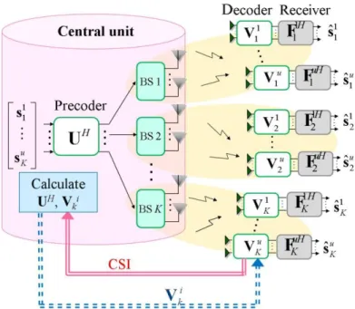
In this thesis, we consider closed loop UL CoMP communication system which provides better system performance while additional signaling and complexity is needed. The CU stands for the operation of precoder and decoder design based on CSI
information; hence a well-behaved augmented equivalent channel depicted at (2.5) is formed. Compared to DL case, UL CoMP closed loop communication system has higher efficiency and is more applicable to time-varying mobile communication, because no resource-consuming CSI feedback is needed in UL CoMP as illustrated in
Figure 2-9 and Figure 2-10. For simplicity, the case of a single UE in a cell is
considered (u = 1) in this thesis, which can be easily extended to the case of multiple UEs. In this case, the received signals at the kth BS, the received signal from the entire
cooperative set, and the received signal after decoder UH are given respectively by (2.1),
(2.2), and (2.3), but with Vl V and l1 sl s . For all cases, we focus on the scenario 1l
that all UEs have equal number of transmit layers, i.e., dk = d, and a linear MMSE
receiver is adopted for F in (2.4). Perfect channel estimation, perfect power control, and negligible timing advanced are assumed as well.
Figure 2-10: Illustration of DL CoMP closed loop communication system
Sum-rate performance is a major performance index in CoMP systems, and it highly depends on the system model considered. In our work, the proposed transceiver schemes are equipped with a linear MMSE receiver; hence the associated achievable sum-rate is calculated according to [11]. When particular precoders and joint decoder are adopted, the maximum achievable sum-rate is calculated according to the equivalent channel matrix in (2.3). That is, in this case, the optimal receiver F is adopted. The achievable sum-rate employing particular precoders and decoder is depicted as follow:
-1
optimal E log2 det bps/Hz
T
H
H d nn
R Ι R HH , (2.6)
where Rnn E
nnH stands for the correlation matrix of the effective noise n . On the other hand, in our case equipped with linear MMSE receiver (i.e.,
1 MMSE H H H nn R F H HH ), the achievable sum-rate according to (2.4) is given by
MMSE 2 2 1 1 1 E log 1 E log 1 bps/Hz T d K d b H a H i a b i R
, (2.7)
1 -1 , 1 1 T i H nn d i i R Ι H H , (2.8)where we assume each receiver output is decoded independently, and b
a
is the instantaneous SINR corresponding to the bth layer of ath user at the output of receiver. In (2.7), i ab,i(a 1) d b is the instantaneous SINR of the ith output of
receiver corresponding to the ith element of ˆs , and dT d K.
2.3 Interference Alignment in K-user
Interference Channel
Interference alignment (IA) has recently emerged as a generalized multi-user MIMO technique for the X-channel and K-user interference channel scenarios [8]-[9]. The basic idea of IA is to align or compress interference into some limited subspace so the interference can be separated from the desired signal with sufficient degrees of freedom (DoF). The DoF can be provided by multiple antennas, frequency, time, or phase, though multiple-antenna is the most commonly adopted one. Both centralized and distributed IA algorithms have been developed [9],[12]. Distributed IA starts with an arbitrary precoder which induced an optimal decoder at receiver side and then this decoder triggers another algorithm to update the precoder at transmitter side. The algorithm goes back and forth between BSs and user equipments (UEs) to attain interference alignment. Thus distributed IA is more suitable for time division duplex systems and the case with constant channels. In centralized IA, the iterative process is performed by the CU as usually available in CoMP. Thus centralized IA is more
practical for mobile cellular communications. The application of IA in cellular systems has been studied in which multiple UEs are communicating with multiple BSs in distributed CoMP [13]. However, the application of IA to centralized CoMP has not been widely studied. Hence in this thesis, we try to incorporate centralized IA in centralized UL CoMP to achieve better performance.
In the K-user interference channel model, there are K BSs and K UEs, each BS
serving a single UE, i.e. u1, as depicted in Figure 2-11. The transmitted signal sk
from UE in kth cell is intended for kth BS. Each BS processes its own received signal as follows: , -user , 1 K H H k K k k l l l k k l
y U H V s U n , (2.9) , -user , 1 ˆ H H K H H k K k k k l l l k k k l
s F U H V s F U n , (2.10) where H dk Mr k U and H dk dk k F represent the decoder matrix and receiver
matrix, respectively; Vl V and l1 sl s are assumed. 1l
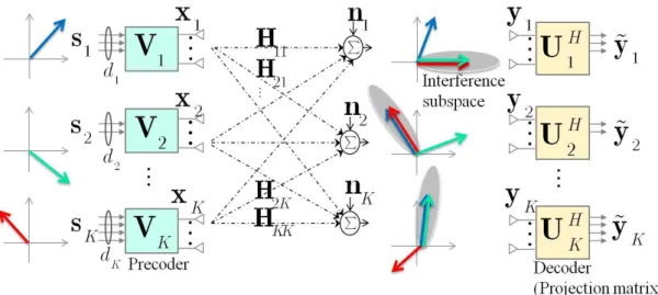
For K-user interference channel, IA has proved to be a capacity achieving approach which aligns the interference into some limited subspace so there would be some residual DoF for the desired signal as illustrated in Figure 2-11. The design criterion of IA is given as follows [9]-[12] (taking kth BS for example):
, , H k k l l l k U H V 0 , (2.11)
,
rank U HHk k kVk dk. (2.12)Figure 2-11: Illustration of IA in K-user interference channel
Several approaches have been proposed to achieve these criteria, e.g. minimum leakage (Min Leakage-IA), maximum SINR (Max SINR-IA) and maximum sum-rate [14]. Min Leakage-IA and Max SINR-IA are two popular iterative IA algorithms [9], [12] which will be adopted in UL CoMP and their performance will be evaluated in our work. These two iterative IA algorithms have advantage of flexibility and can be implemented with various transceiver setups [9], [12]. The iterative procedure based on UL-DL duality is listed in Table 2-1.
Max SINR-IA considers the impact of interference and noise jointly to reach a better compromise at low to moderate SNR by maximizing the SINR of the ith layer corresponding to the kth user, SINRik ( i
1, 2, ,dk
, k
1, 2, ,K
). Each column of decoders is calculated by the algorithm:( ) ( )
( ) ( ) ( ) ( )
, ,
( ) ( ) ( )
max SINR max
i i k k i H i i H H i k k k k k k k k i k i H i i k k k U U U H V V H U U B U , (2.13) ( ) ( ) ( ) ( ) ( ) , , , , 0 . i d d H H i i H H k k l l l k l k k k k k k l d N
B H V V H H V V H I (2.14)
1 ( ) ( ) , ( ) 1 ( ) ( ) , . i i k k k k i k i i k k k k B H V U B H V (2.15)With Uk obtained from previous step, each column of precoders Vk is calculated based
on virtual DL system model by the algorithm:
( ) ( )
2 ( ) ( ) ( ) ( )
, ,
( ) ( ) ( )
max SINR max
i i k k i H H i i H i i k k k k k k k k k k i H i i k k k V V V H U U H V V A V , (2.16) ( ) 2 ( ) ( ) 2 ( ) ( ) , , , , 0 i H d d H H i i H k l l k l l l k k k k k k k k l d N
A H U U H H U U H I, (2.17)where l is chosen to satisfy tr(l2U Ul lH)P. The optimal V for (2.16) is given k( )i
by
Table 2-1: Iterative procedure of Max SINR-IA and Min Leakage-IA Step 1. Start with arbitrary precoders Vk, k {1, 2, …, K}
Step 2. Compute decoders Uk using Max SINR-IA or Min Leakage-IA with Vk
obtained from previous step, k {1, 2, …, K} .
Step 3. Based on virtual DL system model, compute precoder Vk using Max
SINR-IA or Min Leakage-IA with Uk obtained from previous step,
k
{1, 2, …, K} .
Step 4. Go back to Step 2 unless the number of iterations reaches a predefined
limit.
1 ( ) ( ) , ( ) 1 ( ) ( ) , i H i k k k k i k k i H i k k k k A H U V A H U , (2.18)where k is chosen to satisfy tr(V Vk kH)P. The iterative procedure of Max
On the other hand, Min Leakage-IA focuses on (2.11) by minimizing the total interference leakage corresponding to the kth user while assuming (2.12) is automatically satisfied. Each decoder is calculated by the algorithm:
min tr , k H k k k U U Q U (2.19) , ,, H H k k l l l k l l k
Q H V V H (2.20) which yields ( ) eig [ ] d k d k U Q , (2.21)where eig [ ]d A represents the eigenvector corresponding to the dth smallest
eigenvalue of A . With Uk obtained from previous step, each precoders Vk is calculated
based on virtual DL system model by the algorithm:
min tr k H k k k V V Q V , (2.22) 2 , , H H k l l k l l l k l k
Q H U U H , (2.23)where l is chosen to satisfy tr(l2U Ul lH)P. (2.22) and (2.23) yield
( )
eig [ ].
d
k k d k
V Q (2.24)
where k is chosen to satisfy tr(V Vk kH)P. The iterative procedure of Min
Leakage-IA is listed in Table 2-1.
2.4 Summary
To cope with the interference issues in modern mobile communication systems and to further enhance the system performance, CoMP has been proposed as a key
technique. In this chapter, the infrastructure and classification of CoMP are firstly provided, and then the closed loop centralized UL CoMP system adopted in this thesis and its associated mathematical system model are introduced. Moreover, the sum-rate as the performance index is described as well. Finally, a promising technique, interference alignment, aiming at interference mitigation in K-user interference channel is illustrated. The basic idea of IA will be incorporated into one of our proposed transceiver designs.
Chapter 3
Interference Alignment (IA) Aided
Transceiver Design
The interference from other cells which severely degrade the system performance is a crucial factor in modern wireless cellular communication systems and should be carefully managed. To cope with the issues caused by interference such as inconsistent service quality at cell-edge, poor cell coverage, and inferior throughput and to further improve the system efficiency, a promising technique, coordinated multipoint (CoMP) transmission and reception, is developed. In such scenario, the transceiver design based on the full BS cooperation is a critical issue.
In this thesis, two centralized UL CoMP transceiver schemes with multiple transmit antennas, receive antennas, and transmit layers are proposed; the one which incorporates the idea of interference management is provided in this chapter. Interference alignment is a new emerging interference management technique which is developed based on
K-user interference channel structure, and its superior advantage for interference
mitigation has been widely evaluated and discussed in K-user interference channel. The organization of this chapter is shown below. The motivation of the proposed IA aided UL CoMP transceiver scheme is given in section 3.1. In section 3.2, we introduce the incorporation of IA in UL CoMP based on two popular iterative IA
algorithms, Min Leakage-IA and Max SINR-IA provided in [9], [12], and their performances will be evaluated. After the investigation in section 3.2, we propose an IA aided UL CoMP transceiver scheme based on the full cooperation at BSs in section 3.3. Then the numerical evaluation and discussion are provided in section 3.4. Finally, we summarize this chapter in section 3.5
3.1 Motivation
In an interference limited communication environment, there are two typical interference management methods: 1) to decode the desired signal and interference simultaneously and 2) to separate the desired signal from interference by allocating orthogonal/independent physical resource (time, frequency, space, etc.). It is reasonable to infer that incorporating the concept of second approach into the first one can have great potential for dealing with the interference issues.
The inter cell interference which is often treated as noise in the case without BS cooperation is now decodable along with the desired signal at CU owing to the full BS cooperation provided by centralized UL CoMP as illustrated in (2.3). That is the first interference management method mentioned above is provided by centralized UL CoMP. On the other hand, interference alignment is belonging to the second interference management method, and it tries to align the interference into some limited subspace that is independent to the desired signal.
Considering the capability for interference mitigation provided by the two typical interference management methods, we combine the two methods in our first transceiver design which leads to equivalent channel matrix (2.5) reformulation in our work. Hence we aim to capture the basic idea of IA in our precoder and decoder design so that a well-behaved equivalent channel matrix can be obtained.
3.2 Incorporation of IA in UL CoMP
In K-user interference channel, IA intends to align interference at each terminal that inter-user/inter-cell interference can be separated from desired signal and then be alleviated successfully. In this work, we attempt to incorporate IA in our UL CoMP transceiver design (precoder and decoder design as illustrated in section 2.2) where the
interference is aligned and then suppressed at the output of joint decoder UH based on
two popular iterative IA algorithms, Min Leakage-IA and Max SINR-IA provided in [9], [12]. Owing to the intention of interference alignment and mitigation, the residual interference for each layer/user at the output of decoder will be minimized, and a near diagonal /block diagonal effective channel matrix in (2.3) and (2.4) is formed.
According to the system model of centralized UL CoMP depicted in (2.3) and the design principle of IA in K-user interference channel demonstrated in (2.11) and (2.12), the UL CoMP transceiver design which incorporates IA is based on the criteria shown
below (taking kth BS for example, k {1,2, , }K ):
( 1) 1 0, H k d l l k d l k U H V , (3.1) ( 1) 1 rank H k d k k k d d U H V , (3.2) where [ T1,, T2,, , T, ]T KMr Mt l l l K l
H H H H . The main difference between IA in
K-user interference channel and IA in centralized CoMP is that the latter incorporates
full cooperation between BSs for computing the decoders at the BSs. In order to achieve these criteria, we embrace the basic idea of the following two iterative IA approaches developed in K-user interference channel: Min Leakage-IA and Max
SINR-IA [9], [12]. In the rest of this thesis, the UL CoMP transceiver schemes assisted with Min Leakage-IA and Max SINR-IA are called Min Leakage-UL CoMP and Max SINR-UL CoMP, respectively. The two UL CoMP transceiver schemes both involve an iterative procedure based on UL-DL duality, and each iteration consists of two stages: 1) to calculate the joint decoder and 2) to compute the precoders according to the corresponding virtual DL CoMP system.
In regard to Min Leakage-IA aided Uplink CoMP (Min Leakage-UL CoMP) we
obtain the modified optimization problem for joint decoder U from Min Leakage-IA
depicted in (2.19) (taking kth BS for example, k {1,2, , }K ):
( 1) 1
( 1) 1 ( 1) 1 min tr , k d k d k d H k d k k d k d U U Q U (3.3) where k l l lH lH l k
Q H V V H , which yields ( 1) eig [ ], {1, 2, , } k d l l k d U Q l . (3.4)We can obtain precoders by the virtual DL CoMP system. Minimizing the total interference leakage at the UE in kth cell gives
min tr k H k k k V V Q V , (3.5) where k 2 kH
l d(l 1)d 1
(l dl 1)d 1H k l k
Q H U U H , and is chosen to satisfy
2
tr( UUH) K P. This yields
d eig [ ], {1, 2, , }
k k d k d
V Q l , (3.6)
where k is chosen to satisfy tr( )
H
k k P
V V . In this UL CoMP scheme, the Min
Leakage mechanism tries to build a block diagonal effective channel matrix,
H
H U HV. The iterative procedure of Min Leakage-UL CoMP is listed in Table 3-1.
to maximize the SINR corresponding to different layers (data streams) at the output of decoder. Taking into account system model provided by (2.3) and the basic idea of Max SINR-IA, we reformulate (2.13) into the following objective function which aims at
maximizing the SINR of the ith layer corresponding to the kth user, SINRi
k
( i
1, 2, ,d
, k
1, 2, ,K
); each column of decoders is calculated by the algorithm:(( 1) ) (( 1) )
(( 1) ) ( ) ( ) (( 1) ) (( 1) ) ( ) (( 1) ) max SINR max
k d i k d i k d i H i i H H k d i i k k k k k k d i H i k d i k U U U H V V H U U B U , (3.7) ( ) ( ) ( ) ( ) ( ) 0 i t t H H i i H H k l l l l k k k k l t N
B H V V H H V V H I, (3.8) which yields:
1 ( ) ( ) (( 1) ) 1 ( ) ( ) i i k k k k d i i i k k k B H V U B H V , (3.9)
1, 2, ,
,
1, 2, ,
i d k K , where U is the joint decoder matrix as described in
(2.3). For the precoder design, we consider the corresponding virtual DL system model
with which SINRik is maximized: i {1,2, , }d , k {1,2, , }K
( ) ( )
2 ( ) (( 1) ) (( 1) ) ( ) ( ) ( ) ( )
max SINR max
i i k k i H H k d i k d i H i i k k k k k i H i i k k k V V V H U U H V V B V , (3.10) ( ) 2 (( 1) ) (( 1) ) 2 (( 1) ) (( 1) ) 0 i H l d t l d t H k k k l t H k d i k d i H k k N
B H U U H H U U H I , (3.11)
1 ( ) (( 1) ) ( ) 1 ( ) (( 1) ) i H k d i k k i k k i H k d i k k B H U V B H U , (3.12)where k is chosen to satisfy tr(V Vk kH)P. In this UL CoMP scheme, the Max SINR-IA algorithm plays an importance role to convert the original channel into a more
tractable effective channel, HU HVH , which is nearly diagonal. The detail of this
iterative algorithm is summarized in Table 3-1.
Table 3-1: Iterative procedure of Min Leakage-UL CoMP and Max SINR-UL CoMP Step 1. Start with arbitrary precoders Vk, k {1, 2, …, K}
Step 2. Compute the joint decoder U using Min Leakage-UL CoMP (3.4) or Max
SINR-UL CoMP (3.9) with Vk obtained from previous step, k {1,
2, …, K} .
Step 3. Based on virtual DL system model, compute precoder Vk using Min
Leakage-UL CoMP (3.6) or Max SINR-UL CoMP (3.12) with U obtained
from previous step, k {1, 2, …, K} .
Step 4. Go back to Step 2 unless the number of iterations reaches a predefined limit.
After the derivation of the two IA aided Uplink CoMP schemes, the achievable sum-rate performance comparison is provided by numerical simulation as shown in
Figure 3-1. In our simulation, linear MMSE receiver is adopted, and sum-rate
performance is calculated according to (2.7) as mentioned in section 2.2. The simulation results in this section are obtained by averaging over 100 independent channel realizations, and 20 iterations were performed for each iterative algorithm. The entries of the associated channel matrix are assumed i.i.d. complex Gaussian with unit
variance. Three BSs in one cooperative group and one UE in the coverage of each BS
(K = 3, u = 1) are considered. All BSs are equipped with Mr = 4 antennas, and all UEs
are equipped with Mt = 4 antennas. All UEs have equal number of transmit signals, i.e.,
d = 2.
Figure 3-1: Sum-rate performance of Min Leakage-UL CoMP and Max SINR-UL
CoMP with K=3, Mt=4, Mr=4, d=2, and no. of iterations=20
The simulation result shows that Max SINR-UL CoMP significantly outperforms Min Leakage-UL CoMP. The major reason is that Min Leakage-UL CoMP mechanism tries to minimize the interference leakage but assumes (3.2) is automatically satisfied. That is only the interference effect is considered, and there is no guarantee for the detection quality of the desired signal. On the other hand, the Max SINR-UL CoMP algorithm preserves a good compromise between interference and received power of desired signal because it takes both into account. As a potential solution to manage the interference issue and to further improve the system performance, the basic idea of Max SINR-ULCoMP is embraced in our proposed IA aided UL CoMP transceiver
scheme in section 3.3.
3.3 Proposed IA Aided Transceiver in UL CoMP
According to the discussion and simulation result in section 3.2, it is found that Max SINR-UL CoMP achieves better sum-rate performance compared to Min Leakage-UL CoMP, because the first one aided by Max SINR-IA preserves a good compromise between interference and received power of desired signal. In terms of effective channel matrix H , a near diagonal effective channel matrix is accomplished by Max SINR-ULCoMP, since the SINR maximization will somehow suppress the off-diagonal terms of the effective channel matrix. However, since the SINR maximization is executed layer by layer, the SINR performance achieved by each layer might be highly diverse leading to a poor-conditioned effective channel matrix. To improve the condition of the effective channel matrix, it is desired to further balance the layer SINR at the decoder output. Therefore we attempt to propose an IA aided UL CoMP transceiver that can achieve good trade-off between interference issue and received power of desired signal by SINR maximization, and can balance the SINR of each layer at the output of decoder.
The proposed IA aided UL CoMP transceiver is achieved by maximizing the product of instantaneous SINRs for each layer (per-layer SINR), which in turn attempts to increase each per-layer SINR and to reduce the difference between the per-layer SINRs at the output of decoder. Namely, the proposed IA aided UL CoMP scheme aims at maximizing the function shown below:
(( 1) ) ( ) ( ) (( 1) ) (( 1) ) ( ) (( 1) ) , , SINR , k d i H i i H H k d i i k k k k k k d i H i k d i k i k i k
U H V V H U U B U (3.13) ( ) ( ) ( ) ( ) ( ) 0 , i t t H H i i H H k l l l l k k k k l t N
B H V V H H V V H I (3.14)where SINRikis the SINR corresponding to the ith layer of the kth user at the output of
decoder as illustrated in Figure 3-2 ( i
1, 2, ,d
, k
1, 2, ,K
). Theproposed IA aided UL CoMP transceiver scheme involves an iterative procedure as shown in Figure 3-3, and each iteration consists of two stages: 1) to calculate the joint decoder and 2) to compute the precoders.
In the first stage, each column of the joint decoder is computed successively by the algorithm shown below:
(( 1) ) (( 1) )
(( 1) ) ( ) ( ) (( 1) ) (( 1) ) ( ) (( 1) )
, ,
max SINR max
k d i k d i k d i H i i H H k d i i k k k k k k d i H i k d i k i k i k
U U U H V V H U U B U , (3.15) ( ) ( ) ( ) ( ) ( ) 0 i t t H H i i H H k l l l l k k k k l t N
B H V V H H V V H I, (3.16)where i
1, 2, ,d
and k
1, 2, ,K
. The objective function mentionedabove is equal to the criterion,
(( 1) ) (( 1) ) ( ) ( ) (( 1) ) (( 1) ) ( ) (( 1) ) max k d i k d i H i i H H k d i k k k k k d i H i k d i k U U H V V H U U B U , (3.17)
which yields the same results as obtained in Max SINR-UL CoMP:
1 ( ) ( ) (( 1) ) 1 ( ) ( ) i i k k k k d i i i k k k B H V U B H V , (3.18)
1, 2, ,
,
1, 2, ,
i d k K .In the second stage, each column of the precoders is computed successively by the algorithm shown below:
( ) ( )
(( 1) ) ( ) ( ) (( 1) ) (( 1) ) ( ) (( 1) )
, ,
max SINR max
i i k k k d i H i i H H k d i i k k k k k k d i H i k d i k i k i k
V V U H V V H U U B U , (3.19) ( ) ( ) ( ) ( ) ( ) 0 i t t H H i i H H k l l l l k k k k l t N
B H V V H H V V H I, (3.20)where i
1, 2, ,d
and k
1, 2, ,K
. The objective function mentionedabove is equal to the one shown below:
( ) ( ) (( 1) ) ( ) ( ) (( 1) ) (( 1) ) ( ) (( 1) ) , ( , ) ( , ) ( ) (( 1) ) (( 1) ) ( ) ( ) ( ) 1, , 1, (( 1) ) ( , ) ( max max i k i k k d i H i i H H k d i k k k k k d i H i k d i k k i k i k i i H H k d i k d i H i k k k k t t H H l l l l l K t d k d i H l t k
![Figure 2-7: Rate convergence behavior of MMSE transceiver [10] with K = 3, u = 1](https://thumb-ap.123doks.com/thumbv2/9libinfo/8039533.161813/21.892.296.661.765.1078/figure-rate-convergence-behavior-mmse-transceiver-k-u.webp)