國立交通大學
電子工程學系 電子研究所碩士班
碩 士 論 文
具抗錯力之以記憶體為基礎的雙模視訊標準可變長度
解碼器設計
Design of An Error-robust Memory-based VLC
Decoder for Dual-mode Video Decoding
研究生 : 李韋磬
指導教授 : 李鎮宜 教授
具抗錯力之以記憶體為基礎的雙模視訊標準可變長度
解碼器設計
Design of An Error-robust Memory-based VLC
Decoder for Dual-mode Video Decoding
研 究 生:李韋磬 Student:Wei-Chin Lee
指導教授:李鎮宜 Advisor:Chen-Yi Lee
國 立 交 通 大 學
電子工程學系 電子研究所 碩士班
碩 士 論 文
A ThesisSubmitted to Department of Electronics Engineering & Institute of Electronics College of Electrical and Computer Engineering
National Chiao Tung University In Partial Fulfillment of the Requirements
For the Degree of Master In
Electronics Engineering July 2008
Hsinchu, Taiwan, Republic of China
具抗錯力之以記憶體為基礎的雙模視訊標準可變長度
解碼器設計
學生:李韋磬 指導教授:李鎮宜 教授
國立交通大學
電子工程學系 電子研究所碩士班
摘要
本論文提出在支援雙模(H.264/AVC 和 MPEG-2)視訊壓縮標準解碼器下的熵 解碼器中,增進解碼表格在記憶體中的使用效率。此熵解碼器採用多張解碼表格 合併演算法並可程式化以包含不同視訊壓縮標準的熵解碼。首先利用單一表格將 字碼分類到不同的群組,只把各個群組的最重要的資訊存於記憶體中,解碼的過 程只需要用字碼的運算和群組資訊就可以算出符號在記憶體中的位址。在這樣的 結構下,可以比傳統的方式節省記憶體的使用量。視訊壓縮標準的表格相當多 張,因此把需要使用的表格的群組資料再做合併以更減少表格間的贅餘部份而減 少記憶體空間。經由修改演算法可以讓熵解碼器以較少的空間及較高的效率來存 放足夠的資訊。 此論文另外針對視訊無線傳輸的應用下,提出了防止錯誤傳遞的方式而且不 用額外傳輸資料來輔助,也就是幾乎不會增加頻寬成本。這個方式可以利用通道 解碼提供的位元可靠度來決定啟動防止錯誤傳遞的模組,而這個模組裡用記憶體 儲存區塊預測資訊。用這些資訊可以預測出區塊邊界而讓可能出錯的區塊的解碼 不會影響到接下來的區塊。這些資訊的比對是由以記憶體為基礎的可變長度解碼 的方式來決定是否預測成功,在演算上可與傳統的以記憶體為基礎的可變長度解Design of An Error-robust Memory-based VLC
Decoder for Dual-mode Video Decoding
Student : Wei-Chin Lee Advisor : Dr. Chen-Yi Lee
Department of Electronics Engineering
Institute of Electronics
National Chiao Tung University
ABSTRACT
This thesis proposed entropy decoder which can support dual-mode video format (H.264/AVC and MPEG-2) decoding and improved memory efficiency. The entropy decoder adopts multi-table merging (MTM) algorithm and is programmable. First, for a coding table, all codewords are separated into different groups and only the most significant information of each group is stored in memory. The decoding can be completed by looking up information needed and arithmetic computation such that the symbol address is known. Under this type of decoding, memory space can be reduced compared to conventional VLC decoder. For multiple tables, the redundancies between group information of each table are further exploited and only different parts are stored in the memory. By the modified MTM algorithm, the proposed can store information needed for the standards with higher memory efficiency and less memory space.
This thesis also proposed a scheme which can stop error propagation without transmission of extra data helping stop error propagation, i.e., no additional bandwidth overhead. In this method, the stopping error propagation module is activated when the bit reliability coming from FEC is low enough. The error resynchronization information is stored in the memory and block boundary prediction is achieved with the information. Once the block boundary, the following block can be correctly decoded and error propagation can be restricted. The searching of
information used group-based VLC decoding algorithm to determine if prediction is finished. In the algorithm level, the method is combined with conventional group-based VLC decoding; in the viewpoint of hardware implementation, the complexity is low. Owing to stopping error propagation from this scheme, video quality is improved drastically.
Acknowledgements
I am very grateful to my advisor Dr. Chen-Yi Lee because of his patient guidance and very valuable comment for my research. I have learned much experience for research and thinking from him.
Second, I would like to appreciate NSC for the financial support, the teammates of Si2 multimedia group. My seniors like Tsu-Ming Liu and Yao Li gave a lot of suggestion for my thinking and skill training. I am very thankful to them and Yu-De Wu, Yu-Fan Lai. Besides, graduated seniors such as Jun-Yan Yang, Yi-Hung Huang, Kon-Zeng Hou, Zeng-Chie Hsien, Bin-Chang Lin, Yua-Chih Hong and Da-Jiah Lin also shared much experience with me for my graduate life. Finally, I want to express the gratitude for senior Ching-Che Chung’s work on the setting and testing of libraries and technology process and building of simulation environment. Besides, Dr. Ti-Hao Chiang and Dr. Hsie-Chia Chang also gave me some precious comment.
Finally, I would like to appreciate my family and my friends for their assistance and encouragement when I feel stress. I wish all of them are healthy and blest perpetually.
Contents
Chapter 1 Introduction...1 1.1 Overview of H.264/AVC...1 1.2 Overview of MPEG-2...3 1.3 VLC and CAVLC ...4 1.3.1 Huffman Code ...4 1.3.2 CAVLC Decoding...4 1.4 Error Robustness...5 1.5 Motivation ...61.6 Organization of the Thesis ...6
Chapter 2 Previous Work ...7
2.1 CAVLC Decoding Process ...7
2.2 VLC Decoder ...8
2.3 Error Robustness on Wireless Video Transmission ...9
Chapter 3 Algorithm of Memory-based VLC Decoding ...14
3.1 Conventional Group-based VLC Algorithm and Decoding Flow...14
3.1.1 Definition of Codeword Groups...14
3.1.2 Intra-Group Decoding Procedure...15
3.1.3 Group Searching Scheme ...16
3.2 Conventional Multi-Table Merging Algorithm and Decoding Flow...18
3.2.1 Collection of Group Information of All Coding Tables...18
3.2.2 Codeword Merging ...18
3.2.3 Prefix Merging ...19
3.2.4 Set Table Information...19
3.2.5 Base Address Merging ...20
3.2.6 Group Information Recovery ...20
3.3 Modified MTM algorithm for Improvement of Memory Efficiency ...22
3.4 Symbol Memory Allocation...26
Chapter 4 Error Resynchronization ...28
4.1 Concept of Error Resynchronization ...28
Chapter 6 Hardware Architecture and implementation ...39
6.1 Overview of Hardware Architecture ...39
6.2 Memory-based VLC Decoder ...40
6.3 Improvement of throughput...42
6.4 Implementation Result ...44
Chapter 7 Conclusion and Future Work ...51
List of Figures
Fig. 1 The block diagram of H.264 encoder ...1
Fig. 2 The block diagram of H.264 decoder ...2
Fig. 3 The distribution of symbols and the Huffman tree...4
Fig. 4 Sequential syntax elements decoding in CAVLC...7
Fig. 5 Examples of short codewords, they can be decoded by arithmetic decoding from the equation in [6]. ...8
Fig. 6 The implementation of HLLT partitions the original big LUT into many small LUTs in [7]. ...9
Fig. 7 Organization of macroblock level concealment delay and...10
Fig. 8 (a) Pixels for average inter-sample difference across boundary (AIDB) calculation and equation in [12] with N=16. (b) Final equation of the AIDB .11 Fig. 9 Pixels of Average difference across frames (ADF) calculation and N = 16...11
Fig. 10 Experimental Set-up for evaluating the performance of the MAP decoder in (a) [13] , (b) [14]...12
Fig. 11 Combing source and channel state space. (a) source state space. (b) channel state space. (c) integrated state space...13
Fig. 12 Grouping of codewords in the table ...15
Fig. 13 One group with address assignment ...15
Fig. 14 PCLC table and intra-/inter- group symbol memory mapping...16
Fig. 15 Group information of the table in Fig. 14...17
Fig. 16 Part of group information of several tables. ...18
Fig. 17 One portion of the groups after codeword merging process...19
Fig. 18 Table information and group information...20
Fig. 19 Example of group information recovery ...21
Fig. 20 Base address adjustment procedure. The first number after VLCi. Gn is base address and the +K is the adjusted amount of base address. ...25
Fig. 21 Unused locations for the information memory. ...25
Fig. 22 256-entry symbol memory allocation in VLC decoder for MPEG-2 and H.264 standards.s...27
frame is reduced...32
Fig. 28 Reduction phase of inter-checking. After this reduction the remained EOBs is the EOB library stored in memory. ...32
Fig. 29 A portion of groups of EOBs ...34
Fig. 30 Block diagram of the decoder in the wireless transmission environment. ...35
Fig. 31 Probability of EOBs with length constraints. ...37
Fig. 32 Probability of EOBs that are correctly found in the bitstream. ...37
Fig. 33 Block diagram: controller, bitstream buffer, Memory-based VCL Decoder, Level decoder , coefficient buffer ...40
Fig. 34 Total Block Diagram of memory-based VLC decoder...41
Fig. 35 Stage and timing diagram ...42
Fig. 36 Small Cache for Run (short codewords)...43
Fig. 37 Cycle time of the pre-fetching method ...44
Fig. 38 Throughput of decoding under Foreman sequence under 100MHz. ...46
Fig. 39 Throughput of decoding under Mobile sequence under 100MHz...46
Fig. 40 Throughput of decoding for Foreman sequence under 200MHz. ...47
Fig. 41 Throughput of decoding for Mobile sequence under 200MHz. ...47
Fig. 42 Power chart of different module in mobile test frame for (a) QP=16, (b) QP=34 ...48
Fig. 43 Power chart of different module in akiyo test frame for (a) QP=16, (b) QP=34 ...49
List of Tables
Table 1 H.264/AVC profiles and the corresponding tools ...2
Table 2 The throughput of decoding CAVLC under different resolution ...5
Table 3 The number of groups of tables in CAVLC and the number of MTM groups21 Table 4 The number of groups of tables in MPEG2 and the number of MTM groups22 Table 5 Space of the conventional MTM without base address adjustment and the modified memory allocation ...26
Table 6 Estimation of memory usage for different sets of EOBs ...38
Table 7 Estimation of memory usage for different sets of EOBs. ...38
Table 8 Memory space for VLC decoder...45
Table 9 Gate count and power of different designs. ...45
Chapter 1
Introduction
1.1
Overview of H.264/AVC
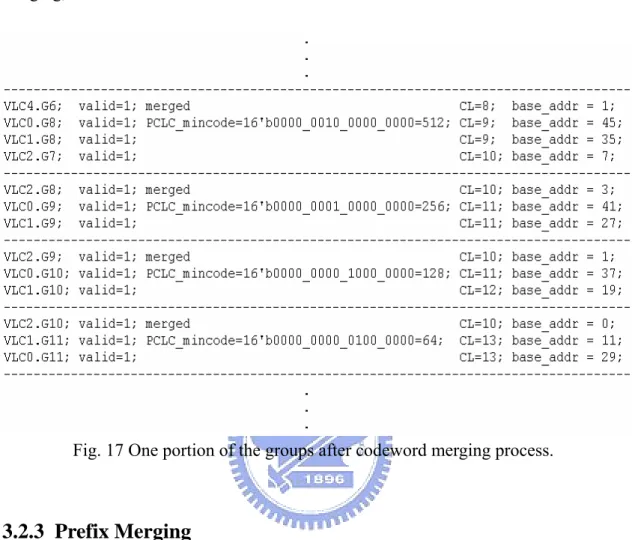
Fig. 1 The block diagram of H.264 encoder
The newest video coding standard is H.264/AVC which was developed by Joint Video Team (JVT). H.264/AVC outperforms the previous video coding standards in the coding efficiency. The block diagram of the H.264 encoder is shown in Fig. 1. The current frame is predicted either by intra prediction or inter prediction. If the frame is an intra frame, all data in the predicted frame come from the current frame. For inter frame, the current frame and reference frame are use to compute motion vectors and compensated by the reference blocks. After prediction, data of current frame subtract that of predicted frame so that only residual data remained. The residual data then passes transformation, quantization, reorder and entropy coding and becomes bitstream. In the backward path, the predicted frame and the residual data are added to form the unfiltered frame for intra prediction. Finally, the reconstructed frame is formed by filtering the uF’n.
Fig. 2 The block diagram of H.264 decoder
Fig. 2 shows the block diagram of H.264 decoder. The first step of decoding is entropy decoding of bitstream. The output data are sent into inverse quantization and inverse integer discrete cosine transform. Now, the data is the residual coefficients between the current frame and the prediction frame. Next step is to add residual data to prediction of current frame (intra or inter). Lastly, the frame passes loop filter to reduce the blocking effect.
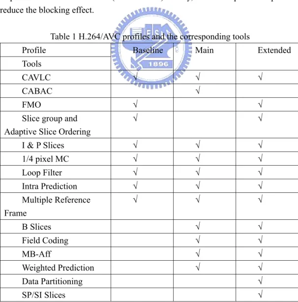
Table 1 H.264/AVC profiles and the corresponding tools Profile
Tools
Baseline Main Extended
CAVLC √ √ √
CABAC √
FMO √ √
Slice group and Adaptive Slice Ordering
√ √ I & P Slices √ √ √ 1/4 pixel MC √ √ √ Loop Filter √ √ √ Intra Prediction √ √ √ Multiple Reference Frame √ √ √ B Slices √ √ Field Coding √ √
For different applications, there are different profiles and tools in H.264/AVC which shows as Table 1. Baseline profile is mainly for mobile applications of low bit rate such as portable devices because of its lower computation complexity than other profiles. Extended profile is based on baseline profile and has error resilient tools for video streaming or video on demand (VOD) applications.
The higher level profile based on baseline profile is main profile which is for broadcast application. The computation complexity of main profile is more than that of baseline profile. In addition, H.264/AVC has the high profile, high 10 profile, high 4:2:2 and high 4:4:4 profiles based on main profile for high definition multimedia applications. The high profile supports 8x8 integer transform and high 10 profile contains high profile with extra support of 10-bit sample precision of the decoded pixels. Further, high 4:2:2 profile based on high 10 profile supports 4:2:2 chroma sampling precision and 10-bit per sample. Finally, high 4:4:4 profile supports 4:4:4 chroma sampling and 12-bit per sample.
From table 1, we can see that there are two entropy coding approaches for entropy coding, one is context adaptive variable length coding and the other is context adaptive binary arithmetic coding. Although CABAC has better compression rate than CAVLC, CABAC has extremely more complex structure which limits the throughput of CABAC than CAVLC. Besides, CAVLC is suitable for all profiles in H.264/AVC system and it has more flexibility for different applications. Therefore, we still further discuss CAVLC in the following sections after the overview of MPEG-2.
1.2 Overview of MPEG-2
MPEG-2 is a video standard established by Moving Pictures Experts Group (MPEG) which is a team of International Standards Organization (ISO). There are five profiles in the MPEG-2 system. The simple profile supports 4:2:0 sampling, intra and inter prediction. Main profile contains all tools of simple profile plus bi-direction prediction. In addition, SNR scalable profile and spatially scalable profile provide the base layer and one or more upper layer of coded bitstream for wider and different application conditions. Finally, the high profile contains all previous tools and it is for the applications where there are no constraints on bit rate.
There are four levels specified in MPEG-2: High level, High 1440, Main level, and Low level. Higher level supports higher resolution of video. Main Profile and Main level is the most widely accepted combination for the majority of applications.
1.3 VLC and CAVLC
1.3.1 Huffman Code
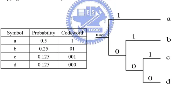
The Huffman code can encode one source with variable length code (VLC) based on the probability distribution of the source symbols. For example, a source contains four symbols ― { a, b, c, d } and the probability of them are 0.5, 0.25, 0.125 and 0.125, respectively. Therefore, we can trace the tree structure to assign codewords for the symbols as shown in Fig. 3. If we use 2-bits codewords to encode the source, the average length is 2 x 0.5 + 2 x 0.25 + 2 x 0.125 + 2 x 0.125 = 2-bits. However, we can use VLC such that average length is 1 x 0.5 + 2 x 0.25 + 3 x 0.125 + 3 x 0.125 = 1.75-bit. For the decoding process, we can just trace the tree from the root to the leaf and then back to the root to decode the next symbol. In MPEG-2, we can see that the coefficients in the block are encoded by run-level coding. The tables defined the mapping between run-level symbols and codewords.
Symbol Probability Codeword
a 0.5 1 b 0.25 01 c 0.125 001 d 0.125 000
Fig. 3 The distribution of symbols and the Huffman tree.
1.3.2 CAVLC Decoding
symbol according to the context conditions. The encoding and decoding process is still by look-up tables.
It is important to consider the throughput when design CAVLC decoder. The number of macroblocks must be decoded per second for different resolution shown in Table 2. In addition, application of baseline profile is mainly mobile devices, thus the power consumption issue must also be taken into account.
Table 2 The throughput of decoding CAVLC under different resolution 30 frames per second (fps)
QCIF CIF QVGA VGA D1 HD
720p
HD 1080
MB/sec 2970 11880 9000 36000 40500 108000 244800
1.4 Error Robustness
Nowadays, wireless video transmission is more and more popular in daily life. Over wireless channel, noise interference affects the data correctness and then the source decoder will accept erroneous data. For wireless video transmission, the data are variable in length. Therefore, even only one bit is corrupted, the whole bitstream may lose synchronization which degrades video quality drastically.
In channel coding, there are many coding techniques to protect transmitted data by appending redundancy to achieve error correction. Another method is to detect error and signal the request of re-transmission of video data. These two methods need higher bandwidth. However, in some application, the bandwidth is limited and the less redundancy added on data, the less capability of error correction. Besides, forward error correction code can not promise totally correct all erroneous data and decoder input may still have remained erroneous bits in it.
There are some schemes to improve the error robustness in the decoder side. For example, error concealment replaces the corrupted block by surrounding blocks which is correctly decoded and improves the video quality. Nevertheless, an error detection module must also help to find the location of corrupted blocks.
Soft-input decoding is another method to reduce bit error rate (BER) of the decoder input bitstream. Soft-input decoding uses channel information to find the maximum likelihood or maximum a posteriori path of the trellis diagram. In advance, joint source–channel design (JCSD) can improved BER performance by considering trellis structure and symbols probability of source and channel concurrently.
1.5 Motivation
A video decoder can support multi-standard video format is very significant in today’s applications. Most data in the video bitstream is composed of coefficients of blocks. In addition, the first stage of the video decoder is VLC entropy decoder which maps codewords to symbols. As a result, an entropy decoder which is programmable and compatible to different standards with enough throughputs is necessary. Besides, the symbol format of coefficients data is represented by a pair of Run and Level while that of CAVLC is quite different from this.
For the video transmission over wireless environment, we have to find methods to reduce the effect of error propagation. The challenge lies in less information or redundancy remained in the input bitstream of video decoder that can help to detect error and even correct error. Although the whole video transceiver can set as automatically repeat request for the corrupted data, that is, receiver signals a flag to transmitter to re-transmit data. This method results in increasing usage of bandwidth. If soft-input decoding or JSCD is used, high complexity and cost are inappropriate to hardware implementation.
1.6 Organization of the Thesis
The chapter 2 will discuss the previous works about VLC decoder of different implementation and target applications first. Then the previous works of error robust on decoder side only or JSCD will be mentioned. Chapter 3 will show the CAVLC operation and the design of memory-based VLC decoder supporting multiple standards. In the memory-based VLC decoder, multi-table merging algorithm is used and the allocation of memory is considered. Next, we will show the hardware architecture and implementation result in chapter 4. Chapter 5 proposes an algorithm used to find the block boundaries in frames stops error propagation under the condition that channel information is known. Also, the simulation result will be in the chapter 6. Chapter 7 will show the conclusion about the whole design of multi-mode and memory-based VLC decoder with error robustness.
Chapter 2
Previous Work
2.1 CAVLC Decoding Process
There are five syntax elements in CAVLC:Coefficient_Token (Coeff_Token), TrailingOnes_Sign (T1s_Sign), Level_Prefix, Level_Suffix, Total_Zeros and Run_Before. They are decoded in order defined by the following rules and the block data composed of these syntax elements is shown in Fig. 4
1. The first decoded syntax element is Coeff_Token, which includes to symbol: Total_Coeff and TrailingOnes. Total_Coeff represents number of non-zero coefficients in this block and TrailingOnes represents number of coefficient with magnitude one and it is 3 at most. The sub-tables are select by nC parameter from system. nC is positive for luma and -1 for chroma.
2. TrailingOnes_Sign is decoded by getting TrailingOnes bits from bitstream. 3. Level_Prefix is decoded by leading one detector and is equal to number of zeros
before the leading one.
4. Then, a parameter called SuffixLength is initially set to 0 or 1 if Total_Coeff is greater than 10 and TrailingOnes is less than 3. LevelSuffixSize is set to SuffixLength with two except case: 1. Level_Prefix is equal to 14 and SuffixLength is equal to 0. 2. Level_Prefix is equal to 15. LevelSuffixSize is set to 4 in case1 and 12 in case2. Next, Level_Suffix is decoded by getting LevelSuffixSize bits from bitstream and is set as 0 if LevelSuffixSize is 0.
5. Select Total_Zeros sub-tables according to Total_Coeff. If Total_Zeros is 0, the decoding process is finished.
6. The Zeros_Left is set as Total_Zeros. Run_Before is subtracted from Zeros_Left and the result is assigned to Zeros_Left until Zeros_Left is 0.
2.2VLC Decoder
There are several ways to implement VLC decoder such as memory-based technique, hardwired implementation. [1] proposed group-based algorithm to classify VLC codewords into different groups such that memory just stored group information. In [1], the symbol addresses are calculated by input bit-stream and group information. Last, the symbol memory stored all symbols are accessed to output decoded symbols. The codec can support a coding table with 256-entry 12-bit symbols and 16-bit codewords. Furthermore, [2] proposed the multi-table-merging algorithm to reduce memory space and codec can support JPEG, MPEG-2 and MPEG-4 coding tables. [3] used cache and table partitioning on the group-based VLC decoder to achieve power reduction for MPEG-2. The decoding method in [4] decodes some short codewords by arithmetic operation and the others are mapped into memory to reduce memory access. But [4] was just for Coeff_Token tables and its sequential searching in the memory would lead to low throughput. The scheme proposed by [5] and [6] is that decode short codewords with arithmetic operation while other codewords are decoded by conventional decoding to saving memory access.
Fig. 5 Examples of short codewords, they can be decoded by arithmetic decoding from the equation in [6].
For the hardware implementation proposed by [7], it was ROM-based and used HLLT (hierarchical logic for look-up table, Fig. 6) to improve speed and PCCF (partial combinational component freezing) to reduce power consumption.
Fig. 6 The implementation of HLLT partitions the original big LUT into many small LUTs in [7].
Design of VLC decoder in [8] was for MPEG-1/2/4 decoding and LUTs are implemented by hardwire. The codewords are separated into groups in several look-up tables and one address generator is used to calculate symbol address.
In [9], the multi-symbol for level decoding in CAVLC is proposed to reduce operation frequency while maintain enough throughput for real-time requirement. [10] proposed a modified SuffixLength detector to reduce critical path in level decoding .
2.3
Error Robustness on Wireless Video Transmission
Until now, there has been much research on improvement of error robustness to reduce the effect of error propagation in video decoder, compensation of erroneous data and correction error. They can be mainly separated into two sections: source decoder side only and joint source-channel design.
The error robustness mechanism at the source side only includes error detection, error concealment and error resynchronization. Error detection is to find the location of error data or bits in the blocks. The simplest error detection is syntax-based error
detection, that is, use some rules that violated regular decoding process. For example, a codeword is not found or the value of a variable overflows. [11] made some rules of syntax-based error detection and analyzed the performance of detection. However, the detection has delay between the correctly detected block and exactly erroneous block as shown in Fig. 7
Fig. 7 Organization of macroblock level concealment delay and detection delay in [11]
[12] detected error blocks basically by computing the boundary difference and used threshold as the determination rule. In Fig. 8, L means “Left” and can be replaced by T(TOP), R(Right) or B (Bottom) and K2 is the number of available
(a)
(b)
Fig. 8 (a) Pixels for average inter-sample difference across boundary (AIDB) calculation and equation in [12] with N=16. (b) Final equation of the AIDB
After error detection, error concealment can be activated to compensate the corrupted blocks. Error resynchronization can be achieved by inserting markers in the bitstream to know the boundary of the next decoding unit. In H.264/AVC, one frame can separated into slices and the decoding of one slice would not reference data in other slices. Therefore, if one slice data is corrupted, the error can be restricted in that slice thus the resynchronization is achieved. The other method is inserting refreshment frames, slices or macroblocks so that temporal error propagation can be stopped. [13], [14] and [15] are joint-source channel design for MPEG-4 video format. [13] and [14] simulated the performance of using Maximum A Posteriori (MAP) decoder under additive Markov channels (AMC) and the simulation environment are shown in Fig. 10. [15] combined the source state space with the channel state space to one finite state machine (Fig. 11) and the corresponding trellis decoding can be defined. [16] was a JCSD for H.264 motion vectors data to improve video quality.
(a)
(b)
Fig. 10 Experimental Set-up for evaluating the performance of the MAP decoder in (a) [13] , (b) [14]
Fig. 11 Combing source and channel state space. (a) source state space. (b) channel state space. (c) integrated state space.
Chapter 3
Algorithm of Memory-based VLC
Decoding
3.1 Conventional Group-based VLC Algorithm and Decoding
Flow
This section was previously developed and verified by Bai-Jue Hsieh in [2]. The intention of this section is to quickly talk about the concept of conventional group-based VLC decoder system and how it works.
3.1.1 Definition of Codeword Groups
For a coding table, we separated codewords into groups. Codewords in a group has the following properties:
1. In a group, the codeword can be treated as a binary number which is codeword length-bit long, called VLC_codenum, since the codeword length is the same. 2. The codeword that has the smallest VLC_codenum in a group is denoted
VLC_mincode.
3. A VLC_codeoffset is the offset value between the VLC_mincode and the VLC_codenum.
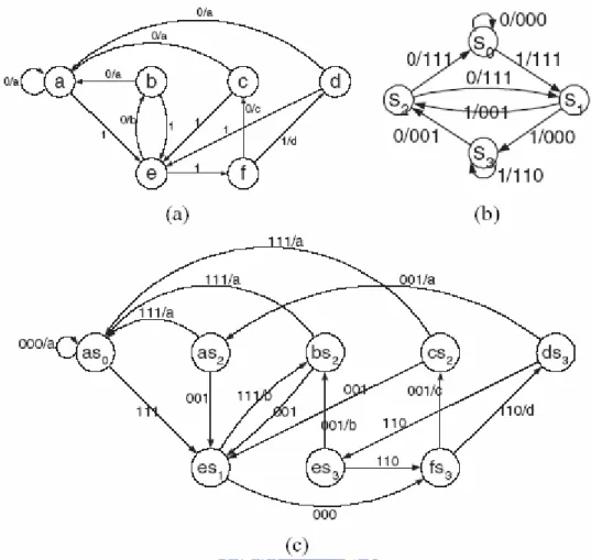
For the example shown in Fig. 12, the VLC table has 8 codewords and the codewords with the same length and prefix are classified as the same group. The codewords in G0 have 4 bits with 2-bit prefix and 2-bit suffix. Therefore, the VLC_codenum are the 0,1,2,3 thus the VLC_codeoffset of Sym5, Sym6, Sym7 are 1,
Prefix Suffix VLC_code num VLC_code offset VLC_mincode Sym8 00 00 0 0 √ Sym5 00 01 1 1 Sym6 00 10 2 2 G0 Sym7 00 11 3 3 G1 Sym1 01 1 0 √ G2 Sym2 10 2 0 √ Sym3 11 0 6 0 √ G3 Sym4 11 1 7 1 Codeword Sym1 01 Sym2 10 Sym3 110 Sym4 111 Sym5 0001 Sym6 0010 Sym7 0011 Sym8 0000
Fig. 12 Grouping of codewords in the table
3.1.2 Intra-Group Decoding Procedure
In the same group, the codewords have arithmetic relationship from the VLC_codenum, VLC_codeoffset and VLC_mincode. Thus, only the VLC_mincode information of every group is stored in memory and we can find the information about other codewords by means of computation of the offset. In other words, if the symbols of the same group are allocated in the continuous location in the symbol memory and the decoded symbol address can be known by adding offset amount to a base address.
Fig. 13 shows the information within one group. For example, if the 0000011 is received, the offset equals to 3 and thus the symbols address is 3 + 60 = 63 to that S3 is decoded.
Symbol Prefix Suffix VLC_codenum VLC_codeoffset Address
S1 000 0 0 60 S2 001 1 1 61 S3 010 2 2 62 S4 011 3 3 63 S5 100 4 4 64 S6 101 5 5 65 S7 110 6 6 66 S8 0000 111 7 7 67
3.1.3 Group Searching Scheme
To search the group that the correct symbol locates in, Pseudo Constant Length Codeword (PCLC) is used. In the table, all codewords are extended to the length of the longest codeword by appending 0’s behind the codewords. All PCLCs have the same length and can be view as binary numbers, PCLC_codenum. All PCLCs are organized in ascending order so that PCLC_codenum0 < PCLC_codenum1 < PCLC_codenum2…PCLC_codenumn and thus PCLC_mincode0 < PCLC_mincode1 < PCLC_mincode2….PCLC_mincoden. Next, the base addresses are assigned to PCLC_mincode and base_addr0 < base_addr1 < base_addr2…..base_addrn. The example of the intra-/inter- group symbol memory mapping is shown in Fig. 14 and the group information of the tables is shown in Fig. 15, where the valid bit means whether the table contains this group or not.
Fig. 15 Group information of the table in Fig. 14
Like the PCLC_codenum, a segment of bitstream with the same length of PCLC can be treated as a binary number, bitstream_num. The group searching scheme can be achieved by computed the (bitstream_num – PCLC_mincodei). The hit condition of the decoded symbol located the group Gn is PCLC_mincoden < bitstream_num < PCLC_mincoden+1.
The overall decoding process of the group-based algorithm is as follows: Assume the bitstream input is 001111100110……
1. Do group searching
ÎPCLC_mincode1(8’b00110000)<bitstream_num < PCLC_mincode2(8’b01000000) ÎThe matching group: G0
2. Send group information
Î code length = 6-bit, PCLC_mincode = 8’b00110000, base_addr(5-bit) = 5’b00100. 3. Find the valid VLC_codeoffset, which is the code length most significant bits
of the result of subtracting the PCLC_mincode from the bitstream_num
ÎBitstream_num(8’b00111110) – PCLC_mincode(8’b00110000) = 8’b00001110. ÎThe valid VLC_codeoffset = 6’b000011= 3.
4. Extract the VLC_codeoffset operand, which has the same word length as the
symbol address
ÎVLC_codeoffset = 5’b00011 = 3. 5. Calculate the decoded symbol address
Îsymbol_addr = base_addr(5’b00100) + VLC_codeoffset(5’b00011) = 5’b00111= 7. 6. Fetch the decoded symbol
3.2 Conventional Multi-Table Merging Algorithm and Decoding
Flow
This section was previously developed and verified by Bai-Jue Hsieh in [2]. The intention of this section is to quickly talk about the concept of conventional multi-table merged VLC decoder system and how it works
3.2.1 Collection of Group Information of All Coding Tables
According to group-based decoding algorithm, group information of all tables can be known and the PCLCs of groups of a table can be viewed as a codeword in that table. Therefore, all PCLCs are collected in the ascending order as Fig. 16 shows. In this figure, all group information items are ordered according to the magnitude of PCLC_mincode and there are 13 items.
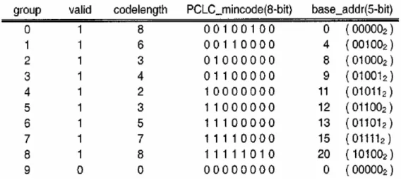
the groups with the same PCLC into the same group and only one PCLC is stored. This reduces storage space. We can see that there are 13 items and after codeword merging, the number of items reduces to 4.
Fig. 17 One portion of the groups after codeword merging process.
3.2.3 Prefix Merging
The prefix merging check any two neighbor groups after codeword merging. When the longest VLC_mincode in a group is the prefix the PCLC_mincode in the adjacent codeword group, they can be merged together to one group. In the case of Fig. 17, there is no prefix merging can be operated.
3.2.4 Set Table Information
After merging process, merged groups and PCLC_mincodes are MTM groups and MTM_PCLC_mincodes, respectively. The table information of a coding table includes the valid-bit and the length of codewords. Because the shortest length of codeword is 1 bit and the length is from 1-bit to 16-bit, we just store (length-1),i.e. 0 ~ 15 in the memory to save memory space. After this shifting operation, the smallest (length-1) in all the groups is defined as MTM_CL-1 and stored in the group
information memory. Therefore, the difference between the larger (length-1) and (MTM_CL-1) which is defined as CL_diff is stored in the table information memory. The memory space is further saved because the data redundancy among the lengths in a MTM group is exploited. The table information and group information are shown in the Fig. 18.
Fig. 18 Table information and group information
3.2.5 Base Address Merging
Although base addresses can be stored for different tables under the given group, the required memory space is large when the number of tables becomes large. [2] proposed a method that classify base address in to categories according to the numbers of table entries. For example, the table1 has 28 entries and table2 has 136 entries, the base addresses of them are classified into two categories: base_addr1 is 5-bit and base_addr2 is 8-bit. With the base address adjustment, different tables with the same category can use common set of base addresses.
group information recovery is shown in Fig. 19. In the first step, (length-1) of VLC_mincode is computed by adding MTM_CL-1 and CL_diff. Second, the most length bits of the MTM_PCLC are assigned to PCLC_mincode while the remained bits are 0s. Finally, the base address is accessed according to base address selection.
Fig. 19 Example of group information recovery
Finally, Table 4and Table 5 shows the number of groups of every table and MTM groups in CAVLC and MPEG-2, respectively. The number of items is reduced greatly in both standards.
Table 3 The number of groups of tables in CAVLC and the number of MTM groups # of Group # of symbols # of group after
MTM Coeff_Token(0<=nC<2) 17 62 Coeff_Token(2<=nC<4) 16 62 Coeff_Token(4<=nC<8) 11 62 Coeff_Token(8<=nC) 7 62 Coeff_Token(nC= -1 ) 8 14 Total_Zeros(TC =1) 9 16 Total_Zeros(TC =2) 8 15 Total_Zeros(TC =3) 8 14 Total_Zeros(TC =4) 7 13 Total_Zeros(TC =5) 7 12 Total_Zeros(TC =6) 7 11 Total_Zeros(TC =7) 8 10 Total_Zeros(TC =8) 7 9 Total_Zeros(TC =9) 7 8 Total_Zeros(TC =10) 6 7 23
Total_Zeros(TC =11) 5 6 Total_Zeros(TC =12) 5 5 Total_Zeros(TC =13) 4 4 Total_Zeros(TC =14) 3 3 Total_Zeros(TC =15) 2 2 Total_Zeros_ch (TC =1) 4 4 Total_Zeros_ch (TC =2) 3 3 Total_Zeros_ch (TC =3) 2 2 Run_Before(ZL = 1) 2 2 Run_Before(ZL = 2) 3 3 Run_Before(ZL = 3) 3 4 Run_Before(ZL = 4) 4 5 Run_Before(ZL = 5) 4 6 Run_Before(ZL = 6) 5 7 Run_Before(ZL > 1) 11 15
Table 4 The number of groups of tables in MPEG2 and the number of MTM groups *: There are 9 locations are unused because the VLC_codnum in one groups are not
continuously increment.
# of Group # of symbols # of group after MTM TB14 13 111
TB15 19 111* 21
3.3 Modified MTM algorithm for Improvement of Memory
Efficiency
Based on the basic concept of MTM algorithm, we applied the algorithm for all coding tables in CAVLC to achieve programmability. The tables include Coeff_Token
adjustment will shift the base address to the maximum value of the group within the same category hence increase the unused locations in symbol memory. Take Coeff_Token (0 <= nC < 2, 2 <= nC < 4, 4 <= nC < 8, 8 <= nC) tables as a example, these four tables are 62-entry and they should belong to 6-bit address category. Fig. 20 shows that most base addresses are adjusted to meet the requirement and we can see that the total shift amount is 83+59+53+52=247. The base address implies the symbol address, as a result, there are 247 entries in symbol memory are unused after the adjustment procedure. The symbol length of Coeff_Token is 7-bit thus there 247 * 7 =1729 bits are unused.
====== Group0: MTM_CL-1=0 1000_0000_0000_0000 ====== VLC0.G0 61 +4 +4 +4 +5 +5 +7 +23 VLC1.G0 60 +5 +7 +4 +2 +4 +4 +4 +2 +21 VLC2.G0 54 +29 +7 +6 +1 +8 +8 VLC3.G0 30 +56 +9 +5 +5 +8 ====== Group1: MTM_CL-1=2 0110_0000_0000_0000 ====== VLC1.G1 59 +5 +7 +4 +2 +4 +4 +4 +2 ====== Group2: MTM_CL-1=1 0100_0000_0000_0000 ====== VLC0.G1 60 +4 +4 +4 +5 +5 +7 VLC1.G2 57 +5 +7 +4 +2 +4 +4 +4 +2 VLC2.G1 46 +29 +7 +6 +1 VLC3.G1 14 +56 +9 +5 +5 ====== Group3: MTM_CL-1=4 0011_0000_0000_0000 ====== VLC1.G3 55 +5 +7 +4 +2 +4 +4 +4 ====== Group4: MTM_CL-1=2 0010_0000_0000_0000 ====== VLC0.G2 59 +4 +4 +4 +5 +5 VLC1.G4 51 +5 +7 +4 +2 +4 +4 +4 VLC2.G2 38 +29 +7 +6 +1 VLC3.G2 6 +56 +9 +5 +5 ====== Group5: MTM_CL-1=4 0001_1000_0000_0000 ====== VLC0.G3 58 +4 +4 +4 +5 ====== Group6: MTM_CL-1=3 0001_0000_0000_0000 ====== VLC0.G4 56 +4 +4 +4 +5 VLC1.G5 47 +5 +7 +4 +2 +4 +4 VLC2.G3 30 +29 +7 +6 +1 VLC3.G3 3 +56 +9 +5 ====== Group7: MTM_CL-1=5 0000_1100_0000_0000 ====== VLC0.G5 55 +4 +4 +4
VLC3.G4 2 +56 +9 ====== Group8: MTM_CL-1=4 0000_1000_0000_0000 ====== VLC0.G6 53 +4 +4 +4 VLC1.G6 43 +5 +7 +4 +2 +4 VLC2.G4 22 +29 +7 +6 +1 ====== Group9: MTM_CL-1=5 0000_0100_0000_0000 ====== VLC0.G7 49 +4 +4 VLC1.G7 39 +5 +7 +4 +2 VLC2.G5 14 +29 +7 +6 +1 VLC3.G5 1 +56 ====== Group10: MTM_CL-1=8 0000_0011_1000_0000 ====== VLC2.G6 13 +29 +7 +6 ====== Group11: MTM_CL-1=6 0000_0010_0000_0000 ====== VLC0.G8 45 +4 VLC1.G8 35 +5 +7 +4 +2 VLC2.G7 7 +29 +7 +6 ====== Group12: MTM_CL-1=7 0000_0001_0000_0000 ====== VLC0.G9 41 +4 VLC1.G9 27 +5 +7 +4 +2 VLC2.G8 3 +29 +7 +6 ====== Group13: MTM_CL-1=8 0000_0000_1000_0000 ====== VLC0.G10 37 VLC1.G10 19 +5 +7 +4 +2 VLC2.G9 1 +29 +7 ====== Group14: MTM_CL-1=9 0000_0000_0100_0000 ====== VLC0.G11 29 VLC1.G11 11 +5 +7 +4 +2 VLC2.G10 0 +29 ====== Group15: MTM_CL-1=12 0000_0000_0011_0000 ====== VLC1.G12 9 +5 +7 +4 ====== Group16: MTM_CL-1=10 0000_0000_0010_0000 ====== VLC0.G12 21 VLC1.G13 5 +5 +7 +4
VLC0.G14 5 VLC1.G15 0 +5 ====== Group19: MTM_CL-1=15 0000_0000_0000_0100 ====== VLC0.G15 1 ====== Group20: MTM_CL-1=14 0000_0000_0000_0010 ====== VLC0.G16 0 ====== Group21: MTM_CL-1=0 0000_0000_0000_0000 ====== VLC3.G6 0
Fig. 20 Base address adjustment procedure. The first number after VLCi. Gn is base address and the +K is the adjusted amount of base address.
From this reason, base address adjustment is not considered as the method of reducing memory space. Nonetheless, direct record of the base address as MTM group information also makes many unused locations in the group information memory. Because there are many small tables in CAVLC and they have short codewords and a few of entries. Usually, the small tables use just one or two groups and other groups are invalid for them. In other words, many entries of group information are unused if the table is small as shown in Fig. 21. In Fig. 21, “TB” represents large tables which have long codewords and many entries while “tb” represents small tables which almost have short codewords and a few entries. The blank blocks is the filed that is unused by the table, i.e., validbit = 0 for that group of a table. For example, TBN does not contain GP0 and valid bit for GP0 is 0 while valid bit for other groups are 1. Also, many fields in the Fig. 21 for tb0~tbm are unused.
Due to the above phenomenon, the modified organization of group information and table information is proposed. First, we use the longest codeword of a table as the determination of whether the table is large or small. We use 4 as the threshold.
Therefore, there are 14 small tables and 16 large tables among CAVLC. Next, the practical storage unit is separated in two parts: one for small tables and one for large tables. By doing this partitioning, the unused locations can be reduced. Originally, the size of the memory space is (n + m) × k and the total size is reduced to n × k + m × ks, where ks is number of groups used by small tables, k is number of groups used by large tables, m is number of small tables, and n is number of large tables. In addition, the PCLC of small tables is shorter than the longest PCLC among all tables. Therefore, size of group information can also be reduced. Table 5 shows the comparison of size for conventional MTM without base address adjustment and the modified memory allocation.
Table 5 Space of the conventional MTM without base address adjustment and the modified memory allocation
Group information size Table information size Total Conventional 23×(16+4+30×8) = 5980 bits 23×30×(1+2) = 2070 bits 8050 bits Modified 23×(16+4+16×8) + 5×(4+2+14×8) = 3994 bits 23×(4×16) + 5×(14×3) = 1620 bits 5676 bits
3.4 Symbol Memory Allocation
Generally, the symbols are store in the symbol memory and symbol lengths of different tables are different. If only one symbol memory is used, the word length must be the length of the longest symbols among all tables. This allocation leads to some wasted space for shorter symbols. In [2], there are several symbol memories with different kinds of word length in order to save the space. The symbol length is
That is, the symbols in Coeff_Token and Total_Zeros/Run_Before can be concatenated into 11-bit words and stored in the 256 × 11 symbol memory. The overhead includes a mask and the multiplexer to choose the format of the symbol according to the standards and decoding tables as shown in Fig. 22. Besides, the start positions of tables are stored in a small register files. As CAVLC is used, we can select the most significant 7 bits of the memory output for Coeff_Token symbols or the least significant 4 bits for Total_Zeros/Run_Before symbols; the whole word is assigned to the symbols for MPEG2.
Fig. 22 256-entry symbol memory allocation in VLC decoder for MPEG-2 and H.264 standards.s
Chapter 4
Error Resynchronization
4.1 Concept of Error Resynchronization
In H.264/AVC error resilient tools, the most important feature is slicing. A slice consists of a sequence of macroblocks (Fig. 23) and the intra-prediction in one slice does not refer to data belongs to the other slices in one frame. If one slice is corrupted during the transmission, the error would not propagate to other slice regions so that the corrupted data is restricted within that slice. Insertion of refreshment frames, slices or macroblocks is a method to stop error propagation in the temporal domain. In addition, [17] mentioned that the insertion of additional markers in the bitstream can achieve VLC resynchronization. From these three methods, we can find that the error propagation can be stopped in a certain region and the following bitstream can be correctly decoded. That is, error resynchronization is achieved. However, these methods have bitstream overhead and increase needed data bandwidth.
Fig. 23 Division of a picture into several slices.
performance. To accomplish error resynchronization, the position of the next decoding unit is necessary so that error will be stopped until the current decoding units. In the following sections, we focus on the I-frame error resynchronization because I-frames are much important than P-frame and I-frame is reference of P-frame.
4.2 Proposed Scheme for Error Resynchronization
The smallest decoding unit in H.264/AVC is 4x4 block and the position of the block can only be known by end of block symbol. Unlike the previous video standards, there is no end-of-block symbol in CAVLC. Take MPEG-2 as an example, TB-14 and TB-15 define the end of block symbol with codeword “10” and “0110”, respectively. As a result, we can try to find the block boundary by searching “10” or “0110” in the bitstream. A further insight into the tables makes these two codewords mistakenly predict the block boundaries because other codewords also contain “10” or “0110”. For instance, codewords of (run, level) = (4, 1), (7, 1) and (2, 2) contain “10” in TB-14; codewords of (run, level) = (4, 1), (1, 2) and (16, 1) contain “0110” in TB-15.
From the conventional CAVLC decoding process, a block with non-zero coefficients has the following steps to complete the decoding: 1. decoding of total coefficients and trailing ones, 2. decoding of sign of trailing ones, 3. decoding of levels, 4. decoding of total zeros, 5. decoding of runs before every non-zero coefficients. The last two steps are about total zeros and runs. Therefore, we can say that end of block consists of these two syntax elements. In bitstream, all combinations of the codewords of theses two tables that meet the rule of CAVLC decoding can be viewed as the EOBs. Since the constructed EOBs have many possibilities, we can choose those ones which are not one segment of combinations of other codewords in the other tables. Once the EOBs are known, the block boundaries can be predicted by them and thus the error can be limited until the current block. Then, the decoding of the next block is resynchronized and correct. The EOB format is shown in Fig. 24.
4.3 EOB Construction
To know all combinational series of codewords from Total_Zeros(T.Z.) and Run_Before(R.B.) tables, we must know all kinds of distribution of coefficients in one 4x4 block. For different distribution of non-zero coefficients, the combinations of the T.Z. codeword and the R.B. codewords are different. The total number of combination can be computed by the following equation (1):
16 16
k k=1
= C , where is the number of coefficients in 4x4 block
Total
∑
k (1)Therefore, there are totally 65535 kinds of EOB and histogram of the distribution is shown in Fig. 25.
16 120 560
1820
4638
8008
11440
12870
11440
8008
4638
1820
560 120 16
0
2000
4000
6000
8000
10000
12000
14000
1
2
3
4
5
6
7
8
9 10 11 12 13 14 15
# of coeff. in 4x4 block
# of
E
OB
s
Fig. 25 Distribution of EOB number at different numb of coefficients
The next step verifies the EOBs that are not segments of combination of other codewords. The EOB is viewed as a sliding window through the whole bitstream and collect those EOBs that only occur at the exact positions. However, the number of total EOBs is large and the total bit of the bitstream is much larger, thus the
short EOBs because short EOBs are more easily found in other places in the bitstream. With EOB positions which are known, the reduced EOBs set is checked in a certain range to determine whether one EOB is unique within the given range. As Fig. 4 shows, the EOB is viewed as a sliding window and check the correlation between the EOB and bitstream. The range is set because in real cases, EOB is not necessary to be unique globally thus only local uniqueness is checked.
Fig. 26 Checking whether the EOB is unique within the given range or not After all EOBs and the corresponding bitstream are checked, the EOBs are reduced because the EOBs that occurred multiple times are removed as shown in Fig. 27. The remained EOBs are defined as intra-set. To ensure EOBs can survive in other frames, they are also checked their uniqueness in other frames. The further reduced set is called the inter-set as shown in Fig. 28. After inter-checking, the remained set can be the error resynchronization information and stored in the memory.
Fig. 27 Reduction phase of intra-checking. The number of EOBs generated from each frame is reduced.
Fig. 28 Reduction phase of inter-checking. After this reduction the remained EOBs is the EOB library stored in memory.
4.4 EOB Storage Using Group-based Scheme
We can treat all EOBs stored in memory as the codewords of a virtual table. From the group-based algorithm we know that the symbol of the decoded codeword
1. Do group searching
ÎPCLC_mincode1(29’b0000_0000_0101_1111_0000_0000_0000_0) < bitstream_num < PCLC_mincode2(29’b0000_0000_0110_1011_0000_0000_0000_0)
ÎThe matching group: G1
2. Send group information
Î code length = 15-bit, PCLC_mincode =
29’b0000_0000_0110_0100_0000_0000_0000_0, base_addr(6-bit) =6’b1000_00.
3. Find the valid VLC_codeoffset, which is the code length most significant bits of the result of subtracting the PCLC_mincode from the bitstream_num
ÎBitstream_num(29’b0000_0000_0110_0110_0000_0000_0000_0) – PCLC_mincode(29’b0000_0000_0110_0100_0000_0000_0000_0) = 29’b0000_0000_0000_0010_0000_0000_0000_0.
ÎThe valid VLC_codeoffset = 15’b0000_0000_0000_001= 1.
4. Extract the VLC_codeoffset operand, which has the same word length as the symbol address
ÎVLC_codeoffset = 6’b0000_01= 1.
5. Calculate the decoded symbol address
Îsymbol_addr = base_addr(6’b1000_00) + VLC_codeoffset(6’b0000_01) = 6’b1000_01= 33.
6. Fetch the decoded symbol
Î sym_memory[33] = S33.
As a consequence, we can store flag as the S33 in the location of address = 33 The flag means if hit or miss for the EOB checking.
PCLC Length-1 Address ---G0--- 0000_0000_0110_1111_0000_0000_0000_0 15 [ 40 ] 0000_0000_0110_1100_0000_0000_0000_0 15 [ 37 ] 0000_0000_0110_1011_0000_0000_0000_0 15 [ 36 ] ---G1--- 0000_0000_0110_1010_0000_0000_0000_0 14 [ 35 ] 0000_0000_0110_1000_0000_0000_0000_0 14 [ 34 ] 0000_0000_0110_0110_0000_0000_0000_0 14 [ 33 ] 0000_0000_0110_0100_0000_0000_0000_0 14 [ 32 ] ---G2--- 0000_0000_0101_1111_0000_0000_0000_0 15 [ 31 ] ---G3--- 0000_0000_0101_1110_0000_0000_0000_0 14 [ 30 ] 0000_0000_0101_1100_0000_0000_0000_0 14 [ 29 ] ---G4--- 0000_0000_0011_1110_0000_0000_0000_0 14 [ 28 ] 0000_0000_0011_1100_0000_0000_0000_0 14 [ 27 ] 0000_0000_0011_1010_0000_0000_0000_0 14 [ 26 ] 0000_0000_0011_1000_0000_0000_0000_0 14 [ 25 ] 0000_0000_0011_0110_0000_0000_0000_0 14 [ 24 ] 0000_0000_0011_0100_0000_0000_0000_0 14 [ 23 ] 0000_0000_0011_0000_0000_0000_0000_0 14 [ 21 ] 0000_0000_0010_1110_0000_0000_0000_0 14 [ 20 ] 0000_0000_0010_1100_0000_0000_0000_0 14 [ 19 ]
Fig. 29 A portion of groups of EOBs
4.5 Joint with Channel and VLC Source Decoder
The bock diagram is shown in Fig. 30. In this error resynchronization scheme, we assume that channel information is available. The system includes the channel side and source side. The source decoder can use the bit reliability which is the
actually bit position. Besides, the method is mainly for random error type.
Bit Reliability Error Bitstream
Channel Source
Channel FEC VLC Video Decoder
Decoder
Chapter 5
Simulation Result
From the proposed algorithm, block boundary prediction by EOBs is a probability issue and EOBs are also VLC, therefore, the length of EOBs has effect on the probability of prediction. On one hand, longer EOB codewords has lower occurrence probability. On the other hand, longer EOB codewords are removed more hardly and have more probability of being in the EOB library finally.
The probability of EOBs that meet length constraints are shown in Fig. 31 and the calculation equation (2) is as follows:
# of EOBs(length > L) occurred probability =
Total # of EOBs (2)
All testing frames are QCIF format and the first 100 frames is the first 100 frames from akiyo sequence, 200~299 frames is the first 100 frames from foreman sequence and the last 100 frames is the last 100 frames from foreman sequence. Fig. 32 shows the probability of correctly found EOBs under three different length constraints. The simulation shows that probability is very close when length is 8 and 10 bits at least and the probability of EOBs (L > 14) is lower.
0 0.1 0.2 0.3 0.4 0.5 0.6 1 25 49 73 97 121 145 169 193 217 241 265 289 Frame Number P roba bi lit y Length > 8 Length > 10 Length > 14
Fig. 31 Probability of EOBs with length constraints.
0 0.1 0.2 0.3 0.4 0.5 0.6 0.7 0.8 0.9 1 1 25 49 73 97 121 145 169 193 217 241 265 289 Frame Number P ro ba bility Length > 8 Length > 10 Length > 14
Table 6 and Table 7 show the memory space for different sets of EOBs. Different grouping strategy makes memory space of group information and symbol quite different. If we separate EOBs into groups by position of leading one (prefix), number of groups is small while the maximum symbol address is large. In contrary, we separate EOBs into groups by prefix and length condition, number of group is large while maximum symbol address is much smaller than the previous one.
Table 6 Estimation of memory usage for different sets of EOBs Grouping by prefix only
. Length 8 10 14 number of group 17 17 17 max. symbol address 160975 282645 639418 PCLC 29 29 29 symbol memory 1024*256 2048*256 8192*128 base address 10 11 13 group information memory 17*(29+5+10) 17*(29+5+11) 17*(29+4+13) Total 262892 525053 1049358
Table 7 Estimation of memory usage for different sets of EOBs. Grouping by prefix and length
Length 8 10 14 number of group 13323 13034 9454 max. symbol address 20760 20678 23640 PCLC (bits) 29 29 29 symbol memory(bits) 1024*32 1024*32 1024*32 base address(bits) 10 10 10 group information
Chapter 6
Hardware Architecture and
implementation
6.1
Overview of Hardware Architecture
Fig. 33 shows the block diagram of proposed dual-mode memory-based VLC decoder. There are mainly five components: 1) Controller, 2) Input Shift Buffer, 3) Memory-based VLC Decoder, 4) Coefficient Buffer and 5) Level Decoder. The controller assigns the control signals for each syntax element according to nC, maxnumcoeff and enable signal from syntax parser. The controller is implemented by a finite state machine (FSM). The memory-based VLC decoder can support CAVLC and MPEG-2 coefficient decoding. Several control signal are needed to control internal memory and these control signal are directly from chip I/O ports so that the content can be loaded into memory for different video standards. The level decoder is mainly composed by level prefix decoder, level suffix decoder and suffix length. Level prefix is composed of a leading 1 detector and level suffix is decoded by getting bits from bitstream buffer depending on level suffix size. The coefficients buffer consists of 4x4 register array and is controlled by run index and level index such that the decoded runs and levels can be put into buffer in order. The input bitstream buffer is integrated into higher hierarchical module in the H.264/MPEG2 video decoder, which is proposed in [18]. Also, the design is also integrated into the H.264/MPEG2 video decoder in the previous video decoder [18].
Input Bitstream Buffer CAVLC Controller Memory-based VLC Decoder Level Decoder Coefficient Buffer Buffer Controller nC is_cavlc
load group information enable load table information enable load symbol enable load data load address length symbol 1 symbol 2 is_RB is_CT is_TZ enable_lut Symbol Selector nC run index level index input bistream input bistream is_LP is_LS level symbol end level end length Length Selector is_CT is_TZ is_RB 11 4 4 4 4 12 5 5 16 5 5 5 maxnumcoeff 5
Fig. 33 Block diagram: controller, bitstream buffer, Memory-based VCL Decoder, Level decoder , coefficient buffer
6.2 Memory-based VLC Decoder
From the modified MTM algorithm, the VLC decoder has two categories for storing group information and table information. They are selected by table index. Each group information is extracted to compute offset. The final offset is determined by the enable signal from group detectors. The tri-state buffer can viewed as the gate for each group. One group has three data items: offset, base address and (length-1). For each decoding time, only one set of data among all groups is passed by the tri-state buffer while others are floated. After the set of data are passed, (length -1) is returned to bitstream shift buffer in the other module and base address is added to offset to compute symbol address. Finally, symbol memory is accessed to output decoded symbol.
Group Information Memory 1 Table Information Memory 1 Group Information Memory 2 Table Information Memory 2 Group Detectors length-1 offset baes_address Symbol Memory 1 Symbol Memory 2 PCLC Recovery MTM_PCLCi CL-1 length_
diff sign bit
of offset input bitstream length-1 enable decoded symbol 1 decoded symbol 2 table index 16 16 4 4 8 8 8 11 7 5 3
Fig. 34 Total Block Diagram of memory-based VLC decoder
The stage partition of memory-based VLC decoder is briefly shown in Fig. 35 and cycle time of important signals are also shown. The register file generated by memory compiler needs one cycle to read data thus the access of group information and table information memory is viewed as the first stage. After the first stage, the symbol address is known thus the access of symbol memory is the second stage.
The group information and table information memory can be accessed when the table used to decode is known. The example of cycle time is shown as in Fig. 35. The first cycle is reading of memory and address computation and the decoded symbol is outputted in the second cycle. The in_valid signal represents the input bitstream and table idx is valid. The symbol is valid until the second cycle. In the third cycle, next valid data is sent after the controller received the Symbol_valid signal.
Address Calculation input bitstream
Memory Stage Memory Stage
Group, Table Information Symbol CLK table index Bitstream
16
16
8
11
5
11
Run_Before consumes many cycles for a block especially in low-QP video and most codewords of Run_Before tables are short. Therefore, we assume that the short codeword stores information of Run_Before such as length of codewords, symbols and table index.
Fig. 36 shows the block diagrams of memory-based VLC decoder with cache. Only some important signals are annotated for simplicity. Again, the controller send the read_en and write_en signal to activate reading or writing of the cache. If cache hit occurs, the memory-based VLC decoder is disabled and the decoded symbol and length is from the cache. If cache missed, conventional VLC decoder is enabled and the symbol and length are stored in the cache. Looking up cache can be done in one cycle while decoding of memory-based VLC decoder need three cycles. As a result, adding cache is a good method to improve the throughput of the whole decoding.
Short Codeword Cache in_bitstream Zerosleft read_en write_en in_length in_symbol 16 4 2 2 out_length out_symbol hit 2 2 Memory-based VLC Decoder CAVLC Controller enable dec_length dec_symbol is_RB 4 11 1 1 0 0 Symbol Length
Fig. 36 Small Cache for Run (short codewords)
In addition to adding cache, one method is also proposed to improve throughput further. In Fig. 35, the table index is known after the FSM is in Coeff_Token and Total_Zeros states. From the conditions of table transition, the next table used to decode can be known earlier than these two states. As a consequence, group
information and table information can be accessed once the condition is known and the conventional three-cycle stage is reduced to two-cycle stage as shown in Fig. 37. In this figure, current Information Memory_out is known before in_valid is high or in the same cycle as in_valid is high. Therefore, the pre-fetching mechanism can achieve one symbol decoding every two cycles. This method can further improve throughput compared to the original design in this thesis.
in_valid table index Bitstream Information Memory_out Symbol Memory_out Symbol Length-1 Symbol_valid 1 2 3 4 5 6 7 8 9 CLK In 1 In 3 In 5 In 7
address 1 address 3 address 5 address 7
symbol 1 symbol 3 symbol 5 symbol 7 symbol 1 symbol 3 symbol 5 symbol 7
length 1 length 3 length 5 length 7
Fig. 37 Cycle time of the pre-fetching method
6.4 Implementation Result
Table 8 Memory space for VLC decoder
Storage content Number of bits Physical space Table information
memory
Valid bit and CL_diff 16 x 23 x 4+ 14 x 5 x 3 16 x 23 x 4+ 16 x 5 x 3 Group information
memory Base address 16 x 23 x 8 + 14 x 5 x 8
16 x 23 x 8 + 16 x 5 x 8 C.T and TZ/RB Run-Level 256 x 11 256 x 11 Symbol memory C.T for CAVLC 16 x 7 16 x 7
Total 8114 bits 8224 bits
The gate count and power consumption of the designs are shown in Table 9. From this table, the gate count of these design are similar. However, the power consumption of memory-based VLC decoder with cache only is lower than that of memory-based VLC decoder without cache. This shows that the cache storing frequent codewords without replacement can achieve power reduction and improve throughput. The throughput of foreman and mobile sequences under different QP are shown in Fig. 38 and Fig. 39, respectively. From these two figures, the proposed design can achieve HD 720p even for very low QPs under 100MHz. The design can also meet requirement of HD1080p when operation frequency is 200MHz as shown in Fig. 40 and Fig. 41.
Table 9 Gate count and power of different designs.
Gate Count Power Consumption( mW) Memory-based VLC decoder 15.4 k 1.132 Memory-based VLC decoder + cache 17.2 k 1.078 Memory-based VLC decoder + pre-fetch 17.2k 1.017
forman.yuv 0 200 400 600 800 1000 1200 1400 1600 1800 2000 10 14 18 22 26 30 34 38 QP cy ce ls / M B Serial memory-based memory-based + cache memory-based + cache + prefetch HD720p, 30fps HD1080p, 30fps
Fig. 38 Throughput of decoding under Foreman sequence under 100MHz.
mobile.yuv 0 200 400 600 800 1000 1200 1400 1600 1800 2000 10 14 18 22 26 30 34 38 QP cy cl es / M B serial memory-based memory-based + cache memory-based + cache + prefetch HD720p, 30fps HD1080p, 30fps
foreman.yuv 0 200 400 600 800 1000 1200 10 14 18 22 26 30 34 38 QP cy cl es / M B Serial memory-based memory-based + cache memory-based + cache + prefetch HD720p, 30fps HD1080p, 30fps
Fig. 40 Throughput of decoding for Foreman sequence under 200MHz.
mobile.yuv 0 200 400 600 800 1000 1200 1400 1600 1800 2000 10 14 18 22 26 30 34 38 QP cy cl es / M B Serial memory-based memory-based + cache memory-based + cache + prefetch HD720p, 30fps HD1080p, 30fps
Fig. 42 and Fig. 43 show power distribution of each main module for test pattern of mobile and akiyo, respectively. The operating frequency is 100MHz. Memory1 stored the base addresses and table information for large tables and Memory2 stored the base addresses and table information for small tables.
1.44E-04,
12%
9.82E-05,
8%
4.19E-04,
35%
5.42E-04,
45%
Memory1
Memory2
Symbol_meory
Others
(a) QP = 16 for mobile
4.96E-04,
44%
9.53E-05,
8%
8.60E-05,
7%
4.80E-04,
41%
Memory1
Memory2
Symbol_meory
Others
4.79E-04,
31%
5.75E-04,
38%
3.82E-04,
25%
9.38E-05,
6%
Memory1
Memory2
Symbol_meory
Others
(a) QP = 16 for akiyo
5.75E-04,
45%
4.58E-04,
36%
1.45E-04,
11%
9.88E-05,
8%
Memory1
Memory2
Symbol_meory
Others
(b) QP = 34 for akiyoTable 10 shows the comparison of the proposed design. We can see that the proposed design support two different entropy decoding, i.e. MPEG2 and H.264. Besides, the proposed design has error resilience feature for application of wireless video
transmission. These two features are quite different from the other designs.
Table 10 Comparison of other designs and proposed design
[1] NCCU TCSVT’06 [2] NCU ASSCC’07 [3] NCKU Trans. on Multimedia‘08 Proposed
Process 0.18um 0.18um 0.18um 0.09um
Technique Hardwired Hardwired Hardwired Memory-based
Features Parallel
LUT
Multi-symbol for level
Modified level
detector Error resilience
Max
Frequency N/A 102MHz 213MHz 200MHz
Gate
Count 13.1K 13.2K 6.7K 17.2K
Memory
(bits) N/A N/A N/A 8114 bits
Target Format HD1080, 30fps HD1080, 30fps HD1080, 30fps HD1080,30fps Multi-mode MPEG- 1/2/4 H.264 (CAVLC) H.264 (CAVLC) MPEG-2, H.264
![Fig. 6 The implementation of HLLT partitions the original big LUT into many small LUTs in [7]](https://thumb-ap.123doks.com/thumbv2/9libinfo/8224831.170694/20.892.135.760.108.722/fig-implementation-hllt-partitions-original-lut-small-luts.webp)
![Fig. 7 Organization of macroblock level concealment delay and detection delay in [11]](https://thumb-ap.123doks.com/thumbv2/9libinfo/8224831.170694/21.892.226.668.549.856/fig-organization-macroblock-level-concealment-delay-detection-delay.webp)
![Fig. 10 Experimental Set-up for evaluating the performance of the MAP decoder in (a) [13] , (b) [14]](https://thumb-ap.123doks.com/thumbv2/9libinfo/8224831.170694/23.892.144.755.510.968/fig-experimental-set-evaluating-performance-map-decoder-b.webp)