國 立 交 通 大 學
電控工程研究所
碩 士 論 文
基於 RGB-D 影像資訊之即時指拼法辨識
系統
Real-Time Fingerspelling Recognition System
Design Based on RGB-D Image Information
研 究 生:莊惠琪
指導教授:陳永平 教授
基於 RGB-D 影像資訊之即時指拼法辨識系統
Real-Time Fingerspelling Recognition System
Design Based on RGB-D Image Information
研 究 生:莊惠琪 Student:Hui-Chi Chuang
指導教授: 陳永平 Advisor:Professor Yon-Ping Chen
國 立 交 通 大 學
電控工程研究所
碩 士 論 文
A Dissertation
Submitted to Institute of Electrical Control Engineering College of Electrical and Computer Engineering
National Chaio Tung University In Partial Fulfillment of the Requirements
For the Degree of Master In
Electrical Control Engineering June 2014
Hsinchu, Taiwan, Republic of China
i
基於 RGB-D 影像資訊之即時指拼法辨識系統
學生: 莊惠琪
指導教授: 陳永平 教授
國立交通大學電控工程研究所
摘要
溝通是人機互動中非常重要的一環,本論文提出一個以色彩深度影像為基礎的指 拼法辨識系統,分為手掌區域偵測、手勢特徵擷取及指拼法辨識三個部分。首先 是手掌區域偵測部分,先使用膚色偵測與聯通物件法找出膚色區域的輪廓,再利 用距離轉換法決定出膚色區域的特徵點,進而將手臉分離得出手掌區域。接著是 手勢特徵擷取,包括手勢形狀及手勢紋理兩種特徵,先由手掌區域的特徵點找出 手掌骨架,並決定出掌心及指尖位置、手掌方向及各手指向量,作為手勢形狀特 徵,本論文針對無法經由手勢形狀特徵予以辨識的指拼法手勢,提出以局部二質 化模式處理手掌區域之灰階影像,產生手勢紋理特徵後再加以辨識。最後,利用 不同的類神經網路分類器進行指拼法辨識。從實驗結果可知,本系統對於美國手 語中大部分的指拼法,可以達到八成以上的辨識率,為一有效的即時辨識系統。ii
Real-Time Fingerspelling Recognition System
Design Based on RGB-D Image Information
Student:
Hui-Chi Chuang
Advisor: Prof. Yon-Ping Chen
Institute of Electrical Control Engineering
National Chiao-Tung University
ABSTRACT
Communication is a very important part for human-computer interaction. This thesis provides a fingerspelling recognition system with high accuracy rate based on RGB-D image. The system are separated into three parts, including ROI selection, hand feature extraction, and fingerspelling recognition. For the ROI selection, the regions of hand and face are first obtained by skin color detection and connect component labeling (CCL), and then the hand, the ROI, is determined by the feature point extraction based on distance transform. Followed is the hand feature extraction which consists of the hand structure and the hand texture. From the feature points of ROI, the locations of palm and fingertips, palm direction, and finger vectors are formed as the hand structure. In addition to the hand structure, this thesis adopts the LBP operator to generate the hand texture to deal with the fingerspelling not recognizable by the hand structure. Finally, the extracted hand features are sent into the fingerspelling recognition system, which is built with several different neural network classifiers. The experimental results show that this system is an effective real-time recognition system whose accuracy is higher than 80% for most of the fingerspelling in ASL.
iii
Contents
Chinese Abstract ... i English Abstract ... ii Contents ... iii List of Figures ... v Index of Tables... ix Chapter 1 Introduction 1.1 Preliminary ... 1 1.2 System Overview ... 3 1.3 Research Organization ... 5 Chapter 2 Background 2.1 Skin Color Segmentation ... 62.2 Neural Network ... 8
2.3 Local Binary Patterns ... 11
Chapter 3 Fingerspelling Recognition 3.1 Hand Region Detection 3.1.1 Skin Color Extraction ... 13
iv
3.1.2 Feature Points Extraction ... 14
3.1.3 Depth Cutting ... 16
3.2 Hand Gesture Feature Extraction
3.2.1 Hand Direction and Size ... 18
3.2.2 Fingertips Detection ... 19
3.3 Fingerspelling Recognition
3.3.1 Multiple Classifier Based on Hand Structure ... 21
3.3.2 Binary Classifier Based on Local Binary Patterns ... 22
3.3.3 The Fingerspelling Recognition System ... 29
Chapter 4 Experimental Results
4.1 ROI Selection ... 35
4.2 Feature Extraction ... 38
4.3 Fingerspelling Recognition ... 40
Chapter 5 Conclusions and Future Works
5.1 Conclusions ... 49
5.2 Future Works ... 50
v
List of Figures
Fig. 1.1 Software architecture ... 4
Fig. 2.1 Structure of Neural Network ... 8
Fig.2.2 Basic structure of the m-th hidden neuron ... 9
Fig. 2.3 Basic structure of an output neuron ... 10
Fig. 2.4 A 33 block example of LBP operator ... 11
Fig. 2.5 The binary result of LBP operator ... 12
Fig. 2.6 The weighting block of LBP operator ... 12
Fig. 2.7 Circular neighbor-sets for three different values of P and R... 12
Fig. 3.1 Easy examples of distance transform ... 14
Fig. 3.2 The local maximum distance-based feature pixels in different regions... 15
Fig. 3.3 An overlapping example of hand detection ... 16
Fig. 3.4 The depth histogram of Fig.3.3 ... 17
vi
Fig. 3.6 The procedure of fingertips detection ... 20
Fig. 3.7 The input information for the multiple classifier based on hand skeleton ... 21
Fig. 3.8 The structure of the neural network of the multiple classifier based on hand skeleton ... 22
Fig.3.9 The block diagram of the binary classifier based on LBP ... 23
Fig.3.10 An example of obtaining LBP image ... 24
Fig.3.11 Separation of the ROI ... 25
Fig.3.12 LBP feature example of gesture “D” ... 26
Fig.3.13 Average LBP feature of gesture “D” ... 27
Fig.3.14 Average LBP feature of gesture “R” ... 27
Fig.3.15 Difference between two classes ... 28
Fig.3.16 Difference between two classes which is arranged sequentially ... 28
Fig. 3.17 The overall flowchart of Fingersplling reorganization system ... 30
vii
Fig.3.19 The distribution of of the gesture ‘G’, ‘I’, ‘D’ and ‘R’ counted by the
average of 10000 frames. ... 32
Fig.3.20 The flowchart of the sub system for q=1 ... 33
Fig. 3.21 The flowchart of the sub system for q=0 ... 34
Fig.4.1 The skin color regions and the feature points with the areas which are large enough for ROI selection around 1 m from the camera to user ... 36
Fig. 4.2 The depth map with the non-overlap hand and face for ROI selection ... 36
Fig.4.3 The skin color regions with overlap hand and face for ROI selection around 1 m from the camera to user ... 36
Fig. 4.4 The depth map with the overlap hand and face for ROI selection... 37
Fig. 4.5 The detection result of ROI selection with non-overlapping case ... 37
Fig. 4.6 The detection result of ROI selection with overlapping case ... 37
Fig.4.7 The LBP image of the hand gesture which are classified by LBP feature ... 38
Fig. 4.8 The fingertips number extraction ... 39
viii
Fig.4.10 The fingerspelling recognition results for from D to K ... 41
Fig.4.11 The fingerspelling recognition results for from L to S ... 42
ix
Index of Tables
Table 1.1 Specification of Kinect ... 3
Table 3.1 The clusters classified by finger number q ... 29
Table 3.2 The comparison for the first classifier of the gestures q=1 ... 32
Table 3.3 The comparison for the second classifier of the gestures q=1 ... 33
Table 3.4 The comparison of the gestures q=0 ... 34
Table 4.1 The numbers of the classifier that are used for fingerspelling recognition for each alphabet ... 44
1
Chapter 1
Introduction
1.1 Preliminary
User friendly facilities are widely provided in recent technical products. Building up a barrier-free society is what the engineers work for. Communication is a very important part for the interactive between human and computer, so we proposes an auxiliary system that enables the hearing impaired to use technical products.
In this system, the fingerspelling is used as the communication tool. Fingerspelling is the representation of the letters of a writing system, so it is very suitable for the application of hand gesture recognition. As with other forms of manual communication, fingerspelling can be comprehended visually. The simplest visual form of fingerspelling is tracing the shape of gestures in the air. To recognize these gestures, there are some algorithms provided in lots of literatures. For examples, Allen, Asselin and Foulds provided 18 sensors cyber glove [1], Bui and Nguyen used the glove with 6 accelerometers for data collection [2], and Bragatto, Ruas and Lamar adopted color glove based on image processing [3]. With the use of glove, the above methods are not user-friendly when compared with the algorithms developed for bare hand recognition [4,5].
A hand gesture recognition system is usually separate into three stages: foreground segmentation, feature extraction, and hand gestures recognition. Foreground segmentation is used to select the region of interest (ROI), which is the region of hand in the system, and filter out the background. The following stages will
2
only consider in the ROI and the feature will be extracted easier. In the feature extraction stage, the feature points can provide a lot of information of the gesture. Finally, the selected features would be used as the input of hand gestures recognition system to get the final result.
3
1.2 System Overview
The Xbox Kinect has been widely used as the image sensor, including RGB image and depth information, and Table 1.1 shows the specification of Kinect. X. The pixel with lower intensity indicates that the distance between object and camera is smaller, and all the points are set to 0 in the depth image if the sensor is not able to measure their depth. The image captured by Kinect would be delivered into Personal Computer(PC) and then be processed to implement hand gesture recognition. The specification is Intel® Core™ i5-3210M CPU @2.50GHz, 8GB memory, and Windows 7 operation system. The frame rate is about 30 frames per second and the frame is processed using C/C++ and Matlab.
Table1.1 Specification of Kinect Depth sensor range 1m ~ 4m
Field of view
Horizontal field of view: 57 degrees Vertical field of view: 43 degrees Physical tilt range ±27 degrees
Data stream
320×240 16-bit depth @ 30 frames/sec 640×480 32-bit color @ 30 frames/sec
For the software architecture, Fig.1.1 is the flowchart of the proposed system. The first step is that the system receives the RGB and depth images from Kinect and then selects the region-of-interest (ROI). After ROI selection, the feature extraction is implemented. The final step and is the main idea in this thesis is that the overall features are delivered into the fingerspelling recognition system to distinguish different alphabets. The experimental environment is our laboratory and the Kinect camera is at about 130cm height, and the detection distance is between 0.5m to 2m
4
(usually 1m) because of the hardware limitation of Kinect.
ROI Selection
Feature Extraction
Fingerspelling Recognition
5
1.3 Research Organization
The thesis is separated into 5 chapters. The motivation, related researches in recent years, and the system overview are introduced in Chapter 1. Chapter 2 describes some basic knowledge for this work. In Chapter 3, the proposed system which is based on the schemes mentioned in Chapter 2 is introduced in detail. Chapter 4 shows the experimental result. Finally, the conclusions and some future works are discussed in Chapter 5.
6
Chapter 2
Backgrounds
2.1 Skin Color Segmentation
Skin color segmentation is a necessary step that used in the application concerning about human, such as human detection, face detection, and hand detection. The color information of received color image is represented in RGB color space, which is the most commonly used color space in digital images. The RGB color space simplifies the design of computer graphics systems but is not ideal for all applications because the red, green and blue color components are highly correlated. For example, in a 24-bit color graphics system with 8-bits per color channel represented as (R,G,B), that is, red as (255,0,0), green as (0,255,0), and blue as (0,0,255).
YCbCr color space is one of the most popular color space for skin color detection due to robustness of varying illuminant and the minimum overlap between skin color and background color [6]. YCbCr color space has been defined in response to increasing demands for digital algorithms in handling video information, and has since become a widely used model in a digital video. The YCbCr color space is commonly used in image processing as it separates the luminance, in Y component, form the chrominance described through Cb and Cr components, as (2.1)
0.299 0.587 0.114 0.713 128 0.564 128 Y R G B Cr R Y Cb B Y (2.1)where the luminance Y is constructed as a weighted sum of RGB components, and the
7 RGB components.
The parameters of the GMM can be obtained from the training data through the iterative expectation-maximization (EM) technique [7] . After proper parameter estimation, both conditional probability densities for skin and non-skin colors are obtained, denoted as p(X | skin) and p(X | nonskin), where X = [Cr Cb]T. Given this class conditional probabilities of skin and non-skin models, a skin classifier can be built using Bayes classifier [8] . The classification boundary is determined where the likelihood ratio of p(X | skin) and p(X | nonskin) exceeds some threshold based on the ROC(receiver operating characteristics) curve. That is, for a given image pixel xn =[Cr(n) Cb(n)]T, it is classified as skin when it satisfies:
| | | | n n n np skin p skin p skin
K p nonskin p nonskin p nonskin
x x
x x (2.2)
where K is a constant and p(skin) 1p(nonskin). Rearranging (2.2), it becomes:
| ' | 1 n n p skin p nonskin K K p nonskin p nonskin x x (2.3)The threshold K' is usually determined from the ROC curve, which shows the relationship between the true positives and false positives. The Bayes classifier has been widely used for skin segmentation since its simplicity and less computation time. The likelihood ratio in (2.3) is computed to check whether it is larger than the
8
2.2 Neural Network
The neural network (NN) technique can be used for classification to deal with complicated problems, such as image analysis and speech recognition. In general, an NN is often designed as the structure in Fig.2.1 containing one input layer, one hidden layer, and one output layer.
Fig.2.1 Structure of Neural Network
The input layer in the first level can receive the training data x nn, 1, 2, N
and sometimes adds x0=1 as a bias. Following the input layer, the hidden layer is
formed by M neurons where the m-th neuron is shown in Fig.2.1. The m-th neuron is depicted in Fig.2.2 and its output zm is implemented as a function of the combination
of weighted inputs am, given as
(1) (1) 0 1 N m m mi n m n z h a h w x w
, m=1,…,M (2.4)x
Nz
1y
K kKz
Mz
0=1
x
1x
0=1
y
1 (1) MDw
9 where (1) (1) (1)0 0 1 N N m mi n mi n m n n a w x w x w
(2.5)a linear combination of the input xn and the weighting vector wmn 1 ,where n=1,2,,N. Note that the function h(•) is often chosen to transform the data into the range [1,1] and close to 1 and 1, such as the hyper tangent function
( ) x x x x e e h x e e (2.6)
used in this thesis.
The output layer is composed of M output neurons shown in Fig.2.3, whose activation function depends on the nature of the input data and the corresponding distribution of target variables. Commonly, there are two choices for the activation function, linear and logistic sigmoid. The linear function is given as
x x (2.7)
often used for regression cases, so that the output is same as the input of the neuron. As for the logistic sigmoid function, it is expressed as
1 1 x x e (2.8)x
1z
m
Fig.2.2 Basic structure of the m-th hidden neuron
h(a
m)
w
m1w
mNx
Nx
0w
m0a
m10
often used for binary classification cases to effectively transform the data into the range [1,] and close to 1 and. For the binary classification cases investigated in this thesis and to get the best classification, the logistic sigmoid function (2.9) is employed as the activation function for the output yk expressed as
1 1 bk k y e (2.9) where (2) (2) (2) 0 0 1 M M k km m km m k m m b w z w z w
(2.10) (2) (1) (1) (2) 0 0 1 1 M N km mn n m k m n h w w x w w
with zm being the m-th output of previous hidden neurons in (2.4).
z
1y
k
Fig.2.3 Basic structure of an output neuron
(b
k)
w
k1w
kMz
Mz
0w
k0b
k11
2.3 Local Binary Patterns
Local binary patterns (LBP) introduced by Ojala et. al. [9] as a scale texture descriptor is a binary pattern which describes the relationship between a pixel and its neighbor pixels. The center pixel is represented by the resulting 8-bit binary number of its neighbors as the example shown in Fig.2.4 and its binary result is shown in Fig.2.5. The LBP operator performs by setting the central pixel value of the 3 3 neighbor pixels as the threshold. If the gray level value of a neighbor pixel is not less than the center pixel, then set the binary value as 1, else set to be 0. The operator was then extended to use any radius R pixels and number of points P in the neighborhood as indicated by the notation LBPP,R. The LBP value of the center pixel Pc is the
multiplied result of Fig.2.6 and Fig. 2.7 defined as
1 , 1 1 , , 2 n c N n N R c N P P n LBP P P P s g g
(2.11)where gc is the gray value of the center pixel Pc,
n
P
g is the gray value of nth pixel at the radius R, s is the thresholding function given as
1, 00, otherwise
x
s x
(2.12)
where R equals to 1 and N equals to 8 in this thesis.
12
There are three examples for different values of P and R shown in Fig.2.7, where LBP8,1 is the original LBP operator with radius of 1 pixel and 8 sampling
points. The LBP serves for texture representation, which is used across various computer vision fields such as image synthesis, light normalization, and face or expression recognition. In this thesis, experiments with LBP operators show the discriminative power of hand gesture classification.
Fig. 2.5 The binary result of LBP operator
Fig.2.6 The weighting block of LBP operator
13
Chapter 3
Fingerspelling Recognition System
3.1 Hand Region Detection
The first step of hand gesture recognition is to detect the hand regions and some color-based algorithms have been proposed for hand region detection, such as the Adaboost learning algorithm [10] and SIFT [11]. With the use of color image, these proposed algorithms often requires a tremendous amount of computation time and unavoidably encounters the difficulty due to the overlap of face and hand regions. In this thesis, in order to save the computation time and ameliorate the overlap problem we propose a novel algorithm of hand region detection based on the color and depth information achieved from the 360 Kinect, which is separated to parts, the skin color detection, the connect component labeling (CCL), the feature point extraction and the hand-face separating.
3.1.1 Skin Color Extraction
With the skin color segmentation in YCbCr color space, there are still a lot of noise pixels in skin color, so a method to remove them is required. As observed, these noise pixels usually have a small region comparing with the hand and face regions, and thus can be removed by the connected component labeling (CCL) method.
Connected Component Labeling (CCL) [12] is a technique to identify different components and often used to detect connected regions in binary images. This thesis applies a 4-pixel connected component to label interesting regions. In addition to
14
recognizing the connected regions, CCL also compute their areas. If the total number of a connected region is less than a threshold, it will be treated as a noise and then removed. As a result, only connected objects which are large enough are retained. To further improve the selected CCL objects, the dilation operator [12] is employed to fill the holes of connected components. The next step is to distinguish the hand region based on the feature points searched and extracted in the selected CCL objects.
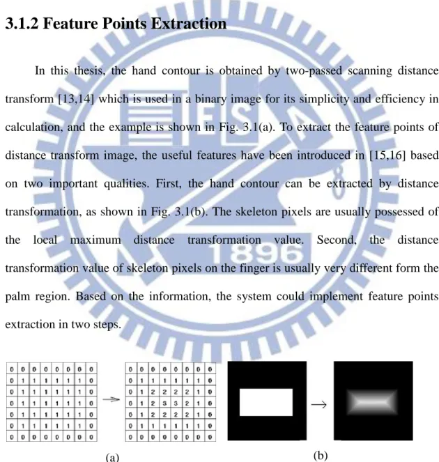
3.1.2 Feature Points Extraction
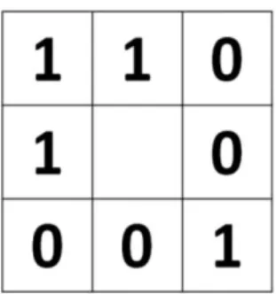
In this thesis, the hand contour is obtained by two-passed scanning distance transform [13,14] which is used in a binary image for its simplicity and efficiency in calculation, and the example is shown in Fig. 3.1(a). To extract the feature points of distance transform image, the useful features have been introduced in [15,16] based on two important qualities. First, the hand contour can be extracted by distance transformation, as shown in Fig. 3.1(b). The skeleton pixels are usually possessed of the local maximum distance transformation value. Second, the distance transformation value of skeleton pixels on the finger is usually very different form the palm region. Based on the information, the system could implement feature points extraction in two steps.
Fig. 3.1 Easy examples of distance transform (a) Shown its distance value (b) Shown its skeleton
15
These distance transformation based feature points can be extracted with the following two steps. First, extract the local maximum pixels based on the distance transformation value. On the distance transformation image, a local maximum pixel would satisfy the following condition:
1 , , i j G x i y j
(3.1)where i,j 1,0,1and the function G is defined as:
1 if
0 otherwise , , , D x y D x i y j G x i y j (3.2)where D(x,y) is the distance transformation value at point (x,y). This condition implies that D(x,y) of the point at (x,y) is greater than or equal to those of its 8 neighborhood pixels, and thus a set of local maximum pixels can be extracted accordingly from the distance transformation image.
The example of choosing feature points is shown in Fig. 3.2, and the condition of feature points extraction is
10DV x y, 3 (3.3)
Fig. 3.2 The local maximum distance-based feature pixels in different regions (b)
16
where the condition is determined by the statistics of the feature points of fingers and the palm. With this condition, the set of the feature points still occurs in the wrist and face regions, so the depth information is used to detect the hand region.
3.1.3 Depth Cutting
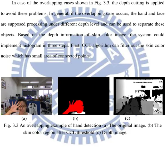
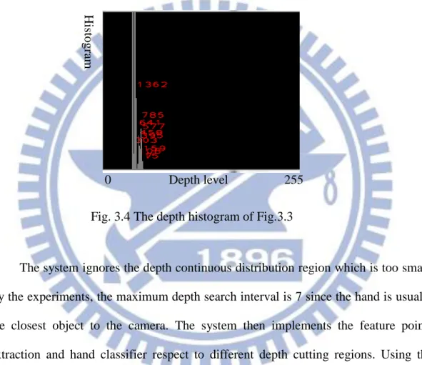
In case of the overlapping cases shown in Fig. 3.3, the depth cutting is applied to avoid these problems. In general, if the overlapping case occurs, the hand and face are supposed processing under different depth level and can be used to separate these objects. Based on the depth information of skin color image, the system could implement histogram in three steps. First, CCL algorithm can filter out the skin color noise which has small area of connected points.
Then, the system computes the depth histogram of the skin color image where the intensity levels are on the range [0, 255]. The depth distribution can be divided into two clusters, one is the hand part that close to the camera and the other is face regions. Let the depth histogram of the skin color image can represented as
1 255
h h h (3.4)
(a) (b) (c)
Fig. 3.3 An overlapping example of hand detection (a) The original image. (b) The skin color region after CCL threshold (c) Depth image.
17
where hi is histogram number related to intensity i, i1~255. The k-th depth region
cutting would satisfy the following condition:
1 k k U j j L h
(3.5)where Lk and Uk indicate the lower and upper bound of k-th depth cutting region,
respectively. The depth histogram is shown in Fig. 3.4.
The system ignores the depth continuous distribution region which is too small. By the experiments, the maximum depth search interval is 7 since the hand is usually the closest object to the camera. The system then implements the feature points extraction and hand classifier respect to different depth cutting regions. Using the refining step can solve this overlapping problem.
0 Depth level 255
Hist
ogra
m
18
3.2 Hand Gesture Feature Extraction
To build up a recognition system, it has to extract useful features to increase the detection rate and decrease the computational cost. The important features of this system are the palm center and fingertips. Based on the distance-based feature points, the palm center, hand direction and fingertip positions can be extracted fast and precisely.
3.2.1 Hand Direction and Size
The direction of the hand is an important cue for recognition, which can be determined by the center of binary hand region and the mean of feature points. The center (xc,yc) of binary hand region is achieved as
h h x x y x x y c c h h x y x y x I x y y I x y x y I x y I x y
,
, , , , , , , , (3.6)where Ih(x,y) is the image of the binary hand region. Similarly, The mean (xm,ym)
of feature points is given as
fp fp x x y x x y m m fp fp x y x y x I x y y I x y x y I x y I x y
,
, , , , , , , , (3.7)where Ifp(x,y) is the image of the feature points. Then, the hand direction can
also be represented by the following angle
1 c m c m y y tan x x (3.8) oriented from (xc,yc) to (xm,ym).
19
camera. The relation of hand size in the image is represented by the hand width and the distance is attained by the depth mean, the mean of all the depth information of the hand contour. From the distribution, the hand size W can be estimated as a linear function of the depth D shown as below:
0 08 218
W . D (3.9)
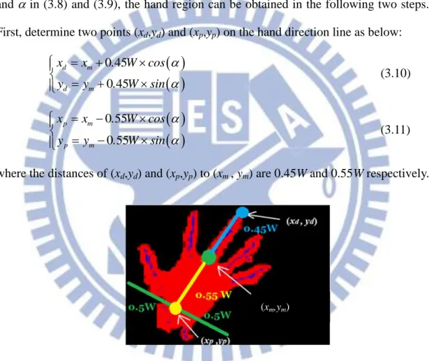
where the coefficient of D and the constant have been discussed in [17]. Based on W and in (3.8) and (3.9), the hand region can be obtained in the following two steps. First, determine two points (xd,yd) and (xp,yp) on the hand direction line as below:
0 45 0 45 d m d m x x . W cos y y . W sin (3.10)
0 55 0 55 p m p m x x . W cos y y . W sin (3.11)where the distances of (xd,yd) and (xp,yp) to (xm , ym) are 0.45W and 0.55W respectively.
Fig. 3.5 The process separating the forearm part
3.2.2 Fingertips Detection
There are many feature points in the fingertips region, and these points can be used to determine the fingertips position quickly and accurately. The dilation operation is implemented to connect the discontinuous feature points first, and then
20
use CCL to label the connected region, called the CCL region. Each CCL region is further processed to determine whether it is a finger or not. If the area of a CCL region is larger than a prescribed threshold T, then it is considered as a finger. The threshold is chosen to be related to the depth D as below [17]:
0.04 55
T D (3.12)
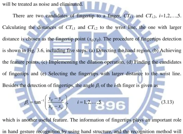
which is obtained experimentally. For those CCL regions with area less than T, they will be treated as noise and eliminated.
There are two candidates of fingertip to a finger, CTi,1 and CTi,2, i=1,2,…,5.
Calculating the distances of CTi,1 and CTi,2 to the wrist line, the one with larger
distance is chosen as the fingertip point (xif,yif). The procedure of fingertips detection
is shown in Fig. 3.6, including five steps: (a) Detecting the hand region, (b) Achieving the feature points, (c) Implementing the dilation operation, (d) Finding the candidates of fingertips and (e) Selecting the fingertips with larger distance to the wrist line. Besides the detection of fingertips, the angle i of the i-th finger is given as
1 tan if p , 1, 2, ,5 i if p y y i x x (3.13)
which is another useful feature. The information of fingertips plays an important role in hand gesture recognition by using hand structure, and the recognition method will be introduced in Sec. 3.3.1.
(a) (b) (c) (d) (e)
21
3.3 Fingerspelling Recognition
3.3.1 Multiple Classifier Based on Hand structure
In the fingerspelling system, the simplest case in this system is 2-finger problem because the hand shape is very different for each other. The hand structure provides hand angle and finger angles to describe the hand gesture. The ways to get the value of hand angle and finger angles are introduced in section 3.2.2. The finger angles are determined by the positions of fingertips and the center of the hand contour, so the finger vectors (ai,bi) are the vectors from hand contour centers to the fingertips where
i=1,2. Thus, there are 5 inputs for the multiple classifier based on hand structure
which are hand angle , the first finger vector a1, b1, the second finger vector a2 and b2
that are shown in Fig.3.7.
The neural network algorithm is applied after then. It contains one input layer with 5 neurons, one hidden layer with 100 neurons, and one output layer with 5
(a
1,b
1)
(a
2
,b
2)
22
neurons. The procedure of neural network has been introduced in Sec 2.2, so the recognition result k is made using the following decision strategy:
arg max q, 1, 2,3, 4,5
q
k y q (3.14)
and the structure of this neural network is shown in Fig.3.8
3.3.2 Binary Classifier Based on Local Binary Patterns
For the cases which are hard to recognize with the information from hand shape such as hand angle and finger angles, the binary classifier based on local binary
a
1z
1y
5 kKz
100z
0=1
a
21
y
2b
1
b
2y
4y
3y
1Fig.3.8 The neural network of the multiple classifier based on hand contour (1)
MD
w
23
pattern (LBP) is provided to deal with the texture of the hand gestures. This classifier can be described by parts, shown as Fig.3.9.
The LBP feature extraction has been introduced in Sec 2.3. Since the LBP operator is used in the gray image problem, the RGB hand gesture contour should be change into gray image. Before LBP operation, the ROI is resized into an image of 200200 pixels, then process the resulted image by the LBP operator. In this thesis, we choose the LBP parameter R1 and N8, which is given in (3.15) and rewritten as
8 1 8,1 1 8 1 , , , , , 2 n c n c c P P n I x y LBP P P P x y s g g
(3.15)where Pc is the pixel under processed and Pn, n1,2,...,8, are its neighbor pixels.
Based on the procedure including (3.15), an ROI in Fig.3.10(a) is used as an example Fig.3.9 The block diagram of the binary classifier based on LBP
LBP feature Difference of LBP feature Threshold number N Threshold value dTh Principle LBP feature Neural Network
24 and the resulted image is shown in Fig.3.10(b).
The resulted image is used to establish the histogram which is considered as the feature of this classifier. The original histogram is created by counting the number of the LBP value of the resulted image from 0 to 255. To simplify the complexity of input data, the LBP value (0~255) is separated into 50 parts, so the change values Ic
should be
5 1 c c I x, y I x, y min n n . (3.16)and the constant 5.1 is the result of 255 divided by 50. The new histogram vector is composed by the components hk shown as
1 1 , , , 0,1, ,50 X Y k c x y h I x y k k
(3.17) where
,
1, for 0, otherwise m k m k (3.18)and X and Y are the width and the height of the processing image. Then the histogram vector H becomes
(a) (b)
Fig.3.10 An example of obtaining LBP image (a) ROI image before LBP operator (b) result image after LBP operator
25
H
h0 h1 h50 0
(3.19)where 0 is the check point and the size of H is 152.
The ROI is separated into 4 parts as Fig.3.11 and repeat the steps 5 times to get 5 different histogram vectors Hk, k04. H0 is the histogram vector of the whole ROI,
and H1 to H4 are the 4-times histogram vectors of the four parts of ROI. Then, these 5
vectors are combined as the LBP feature L, where
L
H0 H1 H2 H3 H4
(3.20)with size 1260 and represented as Fig.3.12.
To deal with the 2-class problem, the difference between LBP features plays an important role. To find out the principle features from L, we collect 10000 frames for both gestures which are giong to classify, numbered as Lk, k=1,2,…,10000. The
average vector of Lk is M expressed as
10000 1 1 10000 k k
M L (3.21)and both classes have their own average vector M1 and M2 which are shown in Fig.
3.13 and Fig. 3.14. The difference between two classes can be expressed as
1 2
D M - M (3.22)
which is shown in Fig. 3.15.
1
2
3
4
Fig.3.11 Separation of the ROI
26
Then, Fig.3.16 is formed by arranging the difference in Fig.3.15 sequentially which makes us easier to find out the threshold value dTh corresponding to the
threshold number N, where N is the number of principle features with difference greater than dTh. The threshold value dTh is determined as the value related to the half
of the AUC (area under curve) denoted in Fig.3.16 where the area left to the red line is 1
2AUC . Later, for different binary classifier, the different threshold number N is used to the input number of the binary neural network classifier. Actually, dTh
N can also be used to determine the order of binary classifiers in cascaded for multiple cases classification. For example, there are three gestures, named as G1, G2 and G3, to
be classified and then we can have three training data D1, D2, and D3. Here, D1 is
achieved by (3.22) and represents the difference between G1 and {G2,G3}. Similarly,
D2 represents the difference between G2 and {G1,G3} and D3 represents the
difference between G3 and {G1,G2}. Hence, the threshold value N1, N2 and N3 for D1,
D2, and D3 can be respectively determined. Assume that 3 2 1
3 2 1
Th Th Th
d d d
N N N , we
27
design a binary neural network classifier C1 with input number N1 to classify the
gestures G1 and {G2,G3}. Further, we design the second binary neural network
classifier C2 cascaded after C1, where C2 is used to classify the gestures G2 and G3.
Fig.3.13 Average LBP feature of gesture “D”
28
After that, the number of the N highest differences of D is noted and take the same number in H as the feature of hand gesture texture and the input of neural network. The neural network consists with N input nodes, 100 hidden nodes and 2 output nodes, and iterates 7000 times. By the neural network, the output goes to 0 or 1, which is the result of binary classify.
Fig.3.15 Difference between two classes
Fig.3.16 Difference between two classes which is arranged sequentially
29
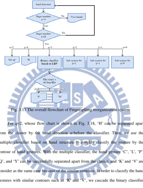
3.3.3 The Fingerspelling Recognition System
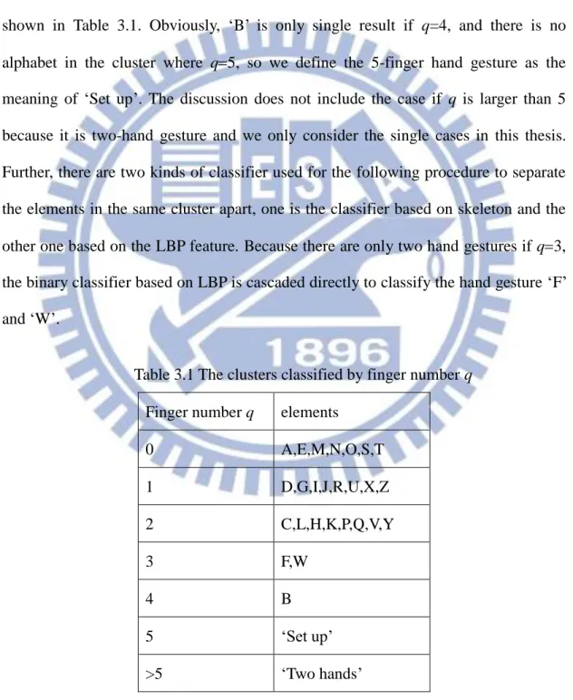
After hand detection, the fingerspelling recognition system whose flowchart is shown in Fig. 3.17 is provided to classify the English alphabets. The first step in this recognition procedure is to roughly classify the hand gesture by the finger number q, and there are 7 clusters after classification. The clusters of this classification are shown in Table 3.1. Obviously, ‘B’ is only single result if q=4, and there is no alphabet in the cluster where q5, so we define the 5-finger hand gesture as the meaning of ‘Set up’. The discussion does not include the case if q is larger than 5 because it is two-hand gesture and we only consider the single cases in this thesis. Further, there are two kinds of classifier used for the following procedure to separate the elements in the same cluster apart, one is the classifier based on skeleton and the other one based on the LBP feature. Because there are only two hand gestures if q3, the binary classifier based on LBP is cascaded directly to classify the hand gesture ‘F’ and ‘W’.
Table 3.1 The clusters classified by finger number q Finger number q elements
0 A,E,M,N,O,S,T 1 D,G,I,J,R,U,X,Z 2 C,L,H,K,P,Q,V,Y 3 F,W 4 B 5 ‘Set up’ >5 ‘Two hands’
30
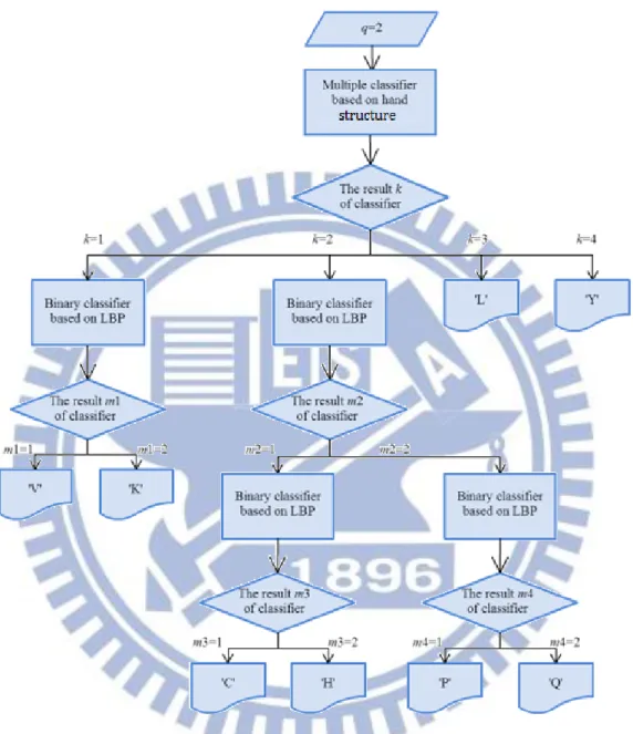
For q2, whose flow chart is shown in Fig. 3.18, ‘H’ can be separated apart from the cluster by the hand direction before the classifier. Then, we use the multiple classifier based on hand structure to roughly classify the gesture by the contour of hand gestures. With the multiple classifier, the hand gesture ‘C’, ’L’, ’P’, ‘Q’, and ‘Y’ can be successfully separated apart from the cluster, and ‘K’ and ‘V’ are consider as the same case because of the similar contours. In order to classify the hand gestures with similar contours such as ‘K’ and ‘V’, we cascade the binary classifier based on LBP after then to deal with this problem.
There are 8 hand gestures in the case of q=1. First, the angle of the only finger of the hand is, and Fig. 3.19 shows the distribution of the with different hand gestures and it is obviously that the of ‘G’ and ‘I’ are significantly different from the others. The hand gesture is considered as ’G’ if is smaller than 40, and ’I’ if is larger than 100. For ‘J’ and ‘Z’, the dynamic hand gestures and cannot be recognize
31
by this system, are considered as the same case with ‘I’ because ‘I’ is also seen as the hand gesture ‘J’ and ‘Z’ without moving.
Next, there are 3 binary classifiers based on LBP cascaded to classify the remaining hand gestures of q=1, and the order of the classifiers is determined by dTh
N which is the ratio of the threshold and the threshold value which is shown in Table 3.2. Based on the comparison in Table 3.2 and Table 3.3, the first binary classifier is going to separate ‘X’ from the other three hand gestures, and the second one is going to
32
separate ‘R’ from the remaining hand gestures, and the last classifier is used to classifier the hand gestures ‘D’ and ‘U’. The flowchart of procedure for q=1 is shown in Fig. 3.20.
Table 3.2 The comparison for the first classifier of the gestures q=1
Cluster 1 Cluster 2 dTh N Ratio
D R,U,X 731 14 52.21 R D,U,X 930 18 51.67 U D,R,X 447 18 24.83 X D,R,U 1280 9 142.2 The prop ortion of
Fig.3.19 The distribution of of the gesture ‘G’, ‘I’, ‘D’ and ‘R’ counted by the average of 10000 frames. (The contour of ‘D’ and ‘R’ is similar to each other and ‘R’, ‘U’ and ‘X’, so the of ‘D’ and ‘R’ can extend to these hand gestures.)
33
Table 3.3 The comparison for the second classifier of the gestures q=1
Cluster 1 Cluster 2 dTh N Ratio
D R,U 780 16 48.75
R D,U 493 9 54.78
U D,R 833 18 46.27
The last cluster is q=0 whose flowchart is shown in Fig. 3.21 is consist with the fist cases. Although there are 7 hand gestures that have to be classified in this part, there are only three hand gestures which are ‘A’, ‘S’, and ‘O’ can be recognized by this system because of the resolution of the Microsoft Kinect. Because there are not any fingers that can provide the hand structure information, we use two binary
34
classifiers based on LBP directly which are cascaded one after another to classify these gestures. Similarly, the comparison of the ratio of dTh and N in Table 3.4
determine the order of the binary classifiers. By the comparison, we design the first classifier in this sub system is used to depart the hand gesture ‘O’ and the other two hand gestures, and the second binary classifier is used to classify the remaining hand gestures ‘A’ an ‘S’.
Table 3.4 The comparison of the gestures q=0
Cluster 1 Cluster 2 dTh N Ratio
A S,O 920 14 65.71
S A,O 640 10 64
O A,S 827 11 75.18
35
Chapter 4
Experimental Result
In this chapter, the experimental result and the accuracy of each step will be shown in detail. OpenCV 2.2 and Matlab R2010b are used to propose the algorithms. There are three main parts which are ROI selection, feature extraction, and fingerspelling recognition system in this system and this chapter contains several experiments for the ASL.
4.1 ROI selection
The very first step of this thesis is ROI selection, which is determined by the skin color and depth information. To examine the reliability of the ROI selection, the procedure of ROI selection is introduced step by step. For the experiment of ROI selection, the hand gesture with five fingers where the feature points are enough to distinguish the hand region and face region is always used to . Fig. 4.1 shows the skin color region and the feature points and Fig. 4.2 is the depth map of the image. In Fig.4.1, there are two candidate areas for ROI in general cases, one is the hand region and the other one is the face region. The feature points (blue points) in hand region is much more than the ones in the face region, so the system can easily recognize the hand region as the ROI. For the overlapping case of hand and other skin color object shown in Fig. 4.3, it might be determined to one object by only RGB information shown in Fig. 4.5, but with depth information shown in Fig. 4.6, the hand and face with different depth value that makes them considered as different object. Fig.5 shows the ROI selection of the general case, and Fig. 4.6 shows the ROI selection of
36
overlapping case where the ROI is blue box shows in Fig. 4.5 and Fig.4.6.
Fig.4.1 The skin color regions and the feature points with the areas which are large enough for ROI selection around 1 m from the camera to user
Fig. 4.2 The depth map with the non-overlap hand and face for ROI selection
Fig.4.3 The skin color regions with overlap hand and face for ROI selection around 1 m from the camera to user
37
Fig. 4.4 The depth map with the overlap hand and face for ROI selection
Fig. 4.5 The detection result of ROI selection with non-overlapping case
38
4.2 Feature Extraction
The features which are used to represent hand structure are fingertips number, finger angles, and hand angles. In first part of this section, there are experiments test the performance of getting these features. Fingertips number is a very important feature, which is the first condition of the fingerspelling recognition system, and the fingertips detection result is shown in Fig. 4.8. The experiment shows the results of fingertips detection and palm center detection with different fingertips number. The other features for fingerspelling recognition are LBP features, which is used for the hand gestures with similar hand structure. In Fig. 4.7, there are some hand gestures which with similar contour or hand structure that we use LBP feature for classification.
Fig.4.7 The LBP image of the hand gesture which are classified by LBP feature
A C D F H
K O P Q R
39
Fig. 4.8 The fingertips number extraction (a) Original image (b) Hand region and hand direction (c) Palm center (red point) and fingertips (yellow points)
40
4.3 Fingerspelling recognition
In this section, the hand gestures will be tested by several classifiers that have been mention in previous sections, Table 4.1 shows the numbers of the classifier that are used for fingerspelling recognition for each alphabet which includes the number of the multiple classifier based on hand structure, the number of the binary classifier based on LBP and the one classifier based on fingertips number. This thesis adopts neural network to implement the fingerspelling recognition system. The main purpose of this thesis is to recognize the alphabets represented by ASL, and Fig.4.9~ Fig.4.12 shows the final result of this system.
41
42
43
44
Table 4.1 The numbers of the classifier Number of the
multiple classifier based on hand structure
Number of the binary classifier based on LBP
Number of classifiers (including the all conditions used for classification) A 0 2 3 B 0 0 1 C 1 1 4 D 0 3 5 F 0 1 2 G 0 0 2 H 1 1 4 I 0 0 1 K 1 1 4 L 1 0 3 O 0 1 2 P 1 1 4 Q 1 1 4 R 0 2 4 S 0 2 3 U 0 3 5 V 1 1 4 W 0 1 2 X 0 1 3 Y 1 0 3
45
Table 4.2 (a) Transition probabilities from the desired hand gestures A to H (lines) to the observable hand gestures (columns)
A B C D F G H A 91.4791 0 0 0 0 0.8276 0 B 0 70.5468 0 0 0 0 0 C 0 0 94.9045 0 0 0 0 D 0 0 0 90.1176 0 0 0 F 0 0.937 0 0 86.8182 0 0 G 0 0 0 4.4706 0 83.8621 5.1576 H 0 0 1.9108 0 0 0 89.1117 I 0 0 0 5.1765 0 0 0 K 0 0 0 0 0 0 0 L 0 0 0 0 0 0 0 O 7.2347 0 0.6969 0 0 12.2759 5.1576 P 0 0 1.2739 0 0 0 0.5731 Q 0 0 0.6369 0 0 0 0 R 0 0 0 0.2353 0 0 0 S 1.2862 0 0 0 0 3.0345 0 U 0 0 0 0 0 0 0 V 0 0 0.6369 0 0 0 0 W 0 28.5162 0 0 13.1818 0 0 X 0 0 0 0 0 0 0 Y 0 0 0 0 0 0 0
46
Table 4.2 (b) Transition probabilities from the desired hand gestures I to R (lines) to the observable hand gestures (columns)
I K L O P Q R A 0 0 0 2.7523 0 0 0 B 0 0 0 0 0 0 0 C 0 0 0 0 0 1.2681 0 D 0 0 0 0 0 0 7.3903 F 0 0 0 0 0 0 0 G 1.4028 0 0 0 0 0 0.9238 H 0 0 0 0 1.8182 0 0 I 98.3968 3.2491 0 0 0 0 3.4642 K 0 91.3357 0 0 0 0 1.3857 L 0 0 96.7557 0 0 0 0 O 0 0 0 96.789 2.9752 3.6739 0 P 0 0 0 0 94.876 0.9058 0 Q 0 0 0 0 0.3306 80.2609 0 R 0 0.1805 0 0 0 0 80.1386 S 0 0 0 0.4587 0 3.8913 0 U 0 0.1805 0 0 0 0 1.8476 V 0 3.7906 3.0534 0 0 0 0.6928 W 0 0 0 0 0 0 0 X 0.2004 1.2635 0 0 0 0 4.157 Y 0 0 0.1908 0 0 0 0
47
Table 4.2 (c) Transition probabilities from the desired hand gestures S to Y (lines) to the observable hand gestures (columns)
S U V W X Y A 13.3705 0 0 0 0 0 B 0 0 0 0 0 0 C 0 0 0 0.4728 0 0.6565 D 0 10.5381 0.5208 0 0.2695 0 F 0 0 0 0.2364 0 0 G 0 6.5022 0 0 0.2695 0 H 0 0 0.7813 0 0 0 I 0 2.4664 7.8125 0 0 0 K 0 0 1.3021 3.3097 0 12.4739 L 0 0 0 0 0 0.6565 O 5.8496 0 0 0 0 0 P 0 0 0 0 0 0 Q 0 0 0 0 0 0 R 0 8.7444 0 0 0 0 S 80.7799 0 0 0 0 0 U 0 71.7489 3.125 0 0.2695 0 V 0 0 86.1979 15.4941 0 1.7505 W 0 0 0 80.487 0 0 X 0 0 0 0 99.1914 0 Y 0 0 0 0 0 84.4639
48
The results shown in Fig.9~12 are used for hand gesture typing or sign language communication, and the accuracy of this system is shown in Table 4.2. In Table 4.2, there are the observation probabilities of alphabets, which are seen as the probabilities that the transition probabilities of the desired hand gestures to observed hand gestures.
In Table 4.2, it is obvious that there are some gestures whose accuracy is under 80%, which are ‘B’ and ‘U’. By the transition probabilities shown in Table 4.2, the fingerspelling of ‘B’ is sometimes misclassified to ‘W’, the misclassification is caused by the wrong fingertips number. ‘B’ has the largest fingertips number in the ASL system, so the feature points of the forth fingertips are sometimes not enough to pass the threshold of finger consideration. For the case of ‘U’, which is sometimes misclassified to ‘D’, the misclassification is caused by the very similar texture of the hand gestures. The LBP features of these hand gestures are not strong enough to classify them in some saturation. Most of the fingerspelling are well classified with the accuracy larger than 80%, that is, the system is useful for fingerspelling recognition.
49
Chapter 5
Conclusions and Future Works
5.1 Conclusions
The main contribution of this thesis is that we propose a robust system fingerspelling recognition system by the user independent hand gesture features, the hand structure and LBP feature which is based on RGB-D image. The system consist with three parts, including ROI selection, feature extraction, and fingerspelling recognition system. The feature points are obtained by the distance transform, which is used to find hand features. The information of hand structure is also created by these feature points which contains hand direction, finger number, and finger vectors. The other hand gesture feature is the texture of hand gesture, which is represented by LBP feature. Finally, these features are sent into the fingerspelling recognition system which is consisted with several classifiers. There are some conclusions generalized by the experimental result:
1. The system provides a high accuracy rate for hand region detection which is used to select the ROI in this thesis. The accuracy is higher than 90% and the average executing time is 0.2sec/frame.
2. The system can detect the hand region correctly even suffering from the overlapping between the hand and the other skin color objects.
3. The hand structure is a fast way to represent the characteristics of the hand contour, and this feature is used to classify the fingerspelling with different hand gesture shape.
50
4. For the cases which are hard to recognize with the information from hand structure, the binary classifier based on local binary pattern (LBP) is provided to deal with the texture of the hand gestures. To simplify the complexity of input data, we separated the LBP value (0~255) into 50 parts, and includes the idea of difference for binary classification.
5. The fingerspelling recognition system is cascaded by the multiple classifiers based on hand structure and binary classifiers based on LBP. The number of classifiers is different for each fingerspelling, and we select the most suitable combination for these classifiers.
6. The accuracy of most fingerspelling are higher than 80%, that is, the system is efficacious for fingerspelling recognition.
5.2 Future Works
The system introduced in this thesis cannot deal with the dynamic hand gesture problem, and is limited by the resolution of Kinect. There are some primary ideas of future works that make the system more complete:
1. The system in this thesis is designed for only one user, so we can extend the system to multi-user fingerspelling recognition system with a little modification of the user interface.
2. With the combination of HMM or the algorithms which are specifically designed to solve the sequential image problems, this system can be extend to the dynamic sign language recognition system. This application is based on the features such as hand structure and hand texture introduced in this thesis, and is more commonly
51 used in accessible communication.
3. This thesis has successfully distinguished many different hand gestures. The one-finger hand gestures can be defined as writing tool which is used for air writing which is also an application of dynamic hand gestures. The writing trajectory can be obtained by the hand information introduced in this thesis such as palm position, finger positions, fingertips vectors, etc. The optical character recognition system has been researched for a long term, so with the combination of the system in this thesis, the air writing recognition can be implemented in efficient way.
52
Reference
[1] Allen, J.M.; Asselin, P.K.; Foulds, R., "American Sign Language finger spelling recognition system," Bioengineering Conference, 2003 IEEE 29th
Annual, Proceedings of , vol., no., pp.285,286, 22-23 March 2003
[2] Bui, T.D.; Nguyen, L.T., "Recognizing Postures in Vietnamese Sign
Language With MEMS Accelerometers," Sensors Journal, IEEE , vol.7, no.5, pp.707,712, May 2007
[3] Bragatto, T. A C; Ruas, G. I S; Lamar, M.V., "Real-time video based finger spelling recognition system using low computational complexity Artificial
Neural Networks," Telecommunications Symposium, 2006 International , vol., no., pp.393,397, 3-6 Sept. 2006
[4] Nagasue, A.; Joo Kooi Tan; Hyoungseop Kim; Ishikawa, S., "Japanese
finger-spelling recognition using a chest-mounted camera," SICE Annual Conference (SICE), 2012 Proceedings of , vol., no., pp.909,912, 20-23 Aug. 2012
[5] Shimada, M.; Iwasaki, S.; Asakura, T., "Finger spelling recognition using neural network with pattern recognition model," SICE 2003 Annual
Conference , vol.3, no., pp.2458,2463 Vol.3, 4-6 Aug. 2003
[6] Terrillon, J.-C.; Shirazi, M.N.; Fukamachi, H.; Akamatsu, S., "Comparative performance of different skin chrominance models and
chrominance spaces for the automatic detection of human faces in color images," Automatic Face and Gesture Recognition, 2000. Proceedings.
53
Fourth IEEE International Conference on , vol., no., pp.54,61, 2000
[7] M.H. Yang, N. Ahuja, "Gaussian Mixture model for human skin color and
its application in image and video databases", Proceedings of SPIE: Conference on Storage and Retrieval for Image and Video Databases, vol.
3656, pp. 458–466,1999.
[8] Steven M. Kay, Fundamentals of Statistical Signal Processing Volume II
Detection Theory: Pearson/Prentice Hall, 1996.
[9] T. Ojala, M. Pietikinen, and D. Harwood, “A comparative study of texture measures with classification based on featured distributions,” Pattern
Recognition, vol. 29, no. 1, pp. 51–59, 1996.
[10] M. A. Al-Mouhamed, O. Toker, and A. Al-Harthy, "A 3-D vision-based man-machine interface for hand-controlled telerobot," Industrial Electronics,
IEEE Transactions on, vol.52, pp.306-319, 2005.
[11] P. Viola and M. Jones, “Robust real-time object detection,” Computer Vision,
International Journal on, vol. 2, no. 57, pp. 137–154, 2004.
[12] R. Laganière, OpenCV 2 computer vision application programming cookbook: Packt Publ. Limited, 2011.
[13] G. Borgefors, "Distance transformations in digital images," Computer vision,
graphics, and image processing, vol. 34, pp. 344-371, 1986.
[14] A. Meijster, J. B. T. M. Roerdink, and W. H. Hesselink, "A general algorithm for computing distance transforms in linear time," Mathematical Morphology and its
54
applications to image and signal processing, pp. 331-340, 2002.
[15] Le Dung; Mizukawa, M., "Fast fingertips positioning based on distance-based feature pixels," Communications and Electronics (ICCE), 2010 Third
International Conference on , vol., no., pp.184,189, 11-13 Aug. 2010
[16] Le Dung and Makoto Mizukawa, " Fast Hand Feature Extraction Based on Connected Component Labeling, Distance Transform and Hough Transform,"
Journal of Robotics and Mechatronics, Vol.21 No.6, 2009
[17] Shi-Cheng Wu (2013) . " Real-Time Hand Gesture Recognition System Design Based on Image Feature Points Extraction and Depth Information, " Master thesis, National Chaio Tung University
[18] G. Borgefors, "Distance transformations in digital images," Computer vision,
graphics, and image processing, vol. 34, pp. 344-371, 1986.
[19] M. Hrúz, J. Trojanová, M. Železný, “Local Binary Pattern based features for sign language recognition,” Pattern Recognition and Image Analysis, Volume 22, Issue 4, pp 519-526, Oct. 2012
[20] Daniel Kelly, John McDonald, Charles Markham, “A person independent system for recognition of hand postures used in sign language,” Pattern Recognition