ELSEWIER
21 July 1997
Physics Letters A 232 ( i 997) 149- 154
PHYSICS LETTERS A
Electra-optical properties of aligned polymer dispersed liquid
crystal films
Jin-Jei Wu a, Chih-Ming Wang b
a Deparrment of Physics, Soochow U~iversi~, Taipei, Tuiwan, ROC
b Institlate of Ekctm-Oprics, Nu~~onal Chiao-Tung Unive~~i~, Hsin-Chu, Tuiwun, ROC
Received 13 August 1996; revised manuscript received 8 April 1997; accepted for publication 24 April 1997 Communicated by A. Lagendijk
Abstract
We study the electro-optical properties of polymer dispersed liquid crystal (PDLC) films with various kinds of alignment. These films are transparent in the electric field-on state and opaque in the field-off state. Experimental data show that the contrast ratio of these aligned films can be higher than that of a usual type PDLC film. The relationship between the field-off state transmittance of such a PDLC film and the polarization of the incident light is discussed. The optical properties of such aligned films can be described by a theory based on Beer’s law. 0 1997 ~blished by Elsevier Science B.V.
1. Intr~uctjon
Polymer dispersed liquid crystal (PDLC) film,
which consists of micron-sized nematic liquid crystal (NLE) droplets dispersed in a polymer matrix, shows an interesting optical property based on voltage-con- trolled light scattering by nematic droplets. Normal- mode operation of PDLC film is characterized by two optically different states, an opaque state under no applied voltage (the off-state) and a transparent state under applied voltage (the on-state) [l-6]. The off-state transmittance of a PDLC usually has maxi- mum refractive index mismatching such that the scattering is at a maximum and the transmittance is at a minimum. Contrary to the off-state, in the case of on-state, the transmittance is at a m~imum be- cause of the refractive index matching. The ratio of the minimum and maximum transmittances is called the contrast ratio. Comparing to a commercial NLC
film, the contrast ratio of current PDLC films is not high enough. Much effort is still needed for improv- ing the contrast ratio of a PDLC film.
Recently, it has been proposed that a PDLC film with dye dissolved in NLC possesses a controllable absorbance as well as a controllable scattering [7- 10). This combination is proved to have some merit for improving the contrast ratio, and is reported in our previous report [lOI. In addition, we report here that a conventional PDLC can be aligned by rubbing the substrate of the film. The alignment for the PDLC film can also improve the contrast ratio.
We fabricated the PDLC films by using a UV
curable polymer as a PDLC material, and to cure the film at suitable UV intensity {IO]. Three kinds of films, plane-parallel, twisted and not aligned PDLC films, were made. In the on-state, the symmetry axis of every NI C droplet of these three kinds of PDLC
films, as shown in Fig. la, is normal to the sub-
03759601/97/$17.00 0 1997 Elsevier Science B.V. All rights reserved. PII SO375-960 I (97)00375-7
(4
(b)
Fig. I. (a> A liquid crystal droplet. The nematic liquid crystal molecules are aligned along the line drawn, and the alignment is symmetric with respect to the droplet axis. (b) In the on-state, most of I, transmits through the PDLC film.
strates. Because the refractive indices of NLC and polymer match each other, the NLC droplets of these three kinds of PDLC films scatter little incident light. Therefore, most of the incident light can pass through the PDLC films. However, in the off-state, most of the droplet axes are not normal to the substrate. Because of the refractive index mismatch between the NLC and polymer, the NLC droplets scatter the incident light.
- --
t
I t - IO IO(b)
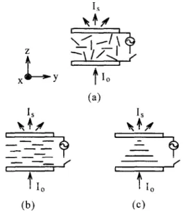
CC)Fig. 2. In the off-state, most of the NLC droplets’ axes are not normal to the glass substrates. The incident light can be scattered by these PDLC films. (a) A conventional PDLC film, (b) a plane-parallel aligned PDLC film, (c) a twist aligned PDLC film.
Comparing the electro-optical properties of these PDLC films, we find that the on-state transmittances of these three kinds of films are almost the same, but the off-state transmittances of these three kinds of films are different from each other. The off-state transmittance of an aligned PDLC film is dependent on the polarization direction of the incident light. We evaluate the contrast ratio of each kind of aligned films and find that for normal incident natural light, the twist aligned PDLC film is better than a conven- tional PDLC film which has no alignment. However, for a linearly polarized incident light, the parallel alignment can have the best contrast ratio. The elec- tro-optical properties of such aligned films are de- scribed by a theory based on Beer’s law. Details of the experimental results and theoretical explanation are reported in this paper.
droplets is polymer in solid phase with refractive index nr, = n,. In the on-state, the symmetry axes of NLC droplets are directed in only one direction, and because np = n, most of the incident light 1, trans- mits through the PDLC film. In the off-state, as shown in Fig. 2, most of the axes are not normal to the glass substrates. And because of the refractive index mismatching of the NIX and the polymer, the incident light I, is scattered by the NLC droplets. The transmittance T of normal incident light can be measured by using the setup shown in Fig. 3. The visible light source can be a He-Ne laser. Because polymer and NLC molecules absorb nearly no visi- ble light, the absorption of the PDLC film is negligi- ble. Similar to Beer’s law, the off-state transmittance of the PDLC film can be expressed as [lo]
T=Z/Z,=exp(-crd), (1)
where I is the transmitted light intensity, (Y is the scattering coefficient and d is the sample thickness
2. Theory beam
We consider a PDLC film as shown in Fig. I b. There are many nematic liquid crystal (NLC) droplets which are randomly distributed in the film. The ordinary and extraordinary refractive indices of the
NLC are n, and n,, respectively. Outside these NLC Fig. 3. Setup for trasmittance measurement. D: photodetector.
(4
J.-J. Wu, C.-M. Wang/ Physics Letters A 232 (1997) 149-154 151
of the film. The scattering coefficient OL is a function
of the materials’ properties, the NIX droplet size and the distribution of droplet axes. If two PDLC films are fabricated using the same materials and under the same conditions except alignment, the NLC droplet sizes can be conceived as the same. The main factor
which makes the scattering coefficients CL of the two
films be different from each other is the alignment of droplet axes.
For a conventional PDLC film in Fig. 2a, no alignment is made. The axes are randomly and uni- formly directed to the 3-dimensions, xyz, space. Let the scattering coefficient of the conventional PDLC film be oj, then o3 is independent of the polariza- tion direction of the incident light. For a twist and a
pl~e-p~allel aligned PDLC film in Fig. 2c and Fig.
2b, the axes are directed in a ‘t-dimensional xy space and a l-dimensional y space, respectively. Because their scattering coefficients depend on the polariza- tion direction of the incident light, we fet their scattering coefficients be o2 ,,, cx 2 I , a, ,, and OL, L .
Here, the subscript 2 represents a 2-dimensional twist; and 1 represents a 1 -dimensional plane-parallel aligned PDLC film. The subscript I] is for the case that the polarization direction of the incident light is parallel to the y-axis; and I is for the case that the polarization direction is normal to the y-axis.
The refractive index of a NLC droplet is about n, in the case that the polarization direction of the incident light is parallel to the droplet axis, and about no if the polarization direction is perpendicular to the droplet axis. The scattering effect comes from the refractive index mismatch between n, and np = n,. Because n, > n, = np for NLC materials, the scatter- ing coefficients cx , I/ is larger than o! I i _ Considering
that the droplets’ axes are distributed in a 3- or
1 -dimensional space, a simple relation for the scatter-
ing coefficients, a: 3r (Y , II and OL 1 I , can be found,
013 = (oil/ +2o,.)/3. (2)
then
~lli’~3>@li * (3)
Similarly, relations for the scattering coefficients
a21p a21 7 ~111 and a,,_ in the following two
extreme cases can be obtained.
Case I: when the NLC droplets axes are twisted
aligned so much, or completely randomly lie in the
xy-plane, then
Q2115~21S h f~,,W. (4)
If n, > n,, then from Eqs. (21, (3) and (41, one can obtain the following relation,
cY,II’01211=a21’(Y3’OLI~. (5)
Case II: when the NLC droplet axes are not twisted aligned so much so that accompanied to the scattering effect the optical adiabatic effect occurs for the direct ~~smitted light, then
~,flZ~Y~f>~39 “3>oL2J.>“,J. - (6)
In practice, a twisted aligned PDLC film should be between the conditions of Case I and Case II.
When the incident light is natural light, the off- state transmittances of the PDLC films can be ex- pressed as
T=T,,+T,
=T, =fexp(-a,,,d)iexp(-o,,d),
for plane-p~allel aligned film,
T- T, = $exp( -cx*,,d) -t- iexp( -aZ1d), for twisted aligned film,
T= T3 = exp( -asd),
for conventional film, (7)
where T,, and T, represent the transmittance of the
incident light with its polarization direction parallel and perpendicular to the aligning direction of the first substrate, respectively.
From Eqs. (21, (41 and (71, and in case that the
scattering coefficient cx 1 ,, + 0, one can obtain the
following result,
T = T,, + T, = T, = +v( -cQ) + I] v
for plane-parallel aligned film,
T= T, = exp( -a,,,d/2), for twisted aligned film, T==T,=exp(-a,,,d/3),
for conventional film. (8)
Because. the fabricating conditions are all the same except the alignment, the on-state transmittances of
these PDLC films have the same value. Therefore, the PDLC film in Case I, where the NLC droplets axes are twisted aligned or randomly lie in the xy-plane, has the best contrast ratio.
However, when the incident light is linearly polar- ized light with its polarization direction parallel to y-axis in Fig. 2, the off-state transmittances of the PDLC films can be expressed as
T=T,,+T,=T,aexp(-cu,,,d), for plane-parallel aligned film, T=T,=exp(-a,,,d/2),
for twisted aligned film,
T= T, = exp( -a,,,d/3),
for conventional film. (9)
Eq. (9) explicitly shows that the plane-parallel aligned film has the lowest off-state transmittance so it has the best contrast ratio.
Eqs. (8) and (9) are the extreme cases under the
assumption IX, I -+ 0, however, in practice 01, I is
not small enough to be negligible.
3. Experiment
In the experiment, two room temperature NLCs are used: E7 and ZLI-2806 (from Merck). The main NLC is E7, a nematic mixture with clearing point at TN1 = 91°C. The second one, ZLI-2806, is the host NIX for diluting a guest-host NIX, ZLI-4821/Z (from Merck), which has been reported in our previ- ous paper [lo].
The principal polymer matrix used is Norland
TV-curable optical adhesive 65 (abbreviated
NOA65) ’ the use of which has been previously
discussed [lo- 121. The four primary constituents of this thiol-ene system are trime~ylolpropane diallyl ether, t~methyIolpropane tris thiol, isophorone diiso- cyanate ester, and benzophenone photoinitiator.
The PDLC material is made by mixing the NLCs
and the prepolymer NOA according to the follow-
ing weight ratios: ZLI-280666%) + E7(54%) + NOA65(40%). With these weight ratios, the NIX
’ Norland Products, Inc., P.O. Box 145, North Brunswick, NJ 08902, USA.
molecules can still be aligned by rubbing the sub- strates. In the experiment, the mixture containing the desired proportions of NLC and polymer precursors is first prepared and spread between two glass sub- strates which have previously been coated with a thin transparent layer of conducting indium tin oxide (ITO). The film thickness is controlled by a 20 * 1 p.,rn mylar spacer. To eliminate errors which come from the thickness or other fabrication conditions in the experiment, we always fabricate sample films with two kinds of alignments on the same substrates. Only half of each glass substrate is rubbed for a
plane-parallel or a 90” twisted alignment, and the
other half is not rubbed for making a conventional PDLC film. To make sure that the sample is uni- formly aligned, we examine the sample with a cross polarizer microscope. Then the sample film is ex- posed to a uniform UV radiation to cure the polymer. The UV light source (Oriel Co., model 66011) is filtered by a band pass filter at wavelength X = 360 nm to 380 nm, and the peak value is at X = 365 nm. The curing intensity is fixed at 50 f 0.1 p_W, and is detected by a UV power detector arranged behind the film. The film is cured for sufficient time till the precursors polymerized enough, which is also de- tected by the UV power detector. When the precur- sors polymerized enough, the transmittance of the UV light does no longer change. During the UV curing, the sample film is put in a chamber of which the temperature is controlled at 25 + 0S”C. We then examine the film using the cross polarizer micro- scope. The size of liquid crystal droplets in the film is uniform.
Let sample 1 be the first kind of sample, half of which is a conventional PDLC film, and the other half is a ~plane-parallel aligned PDLC film; and let sample 2 be the second kind of sample, half of which is a conventional PDLC film, and the other half is a 90” twisted aligned PDLC film. Their electro-optical properties are measured by the setup shown in Fig. 3. The light source in Fig. 3 is a He-Ne laser. After passing through the beam expander and the first aperture, the probe beam with spatially unifo~ly distributed intensity is incident on the sample film and scattered by the film. The scattered light is detected by a detector which is set just behind the second aperture. The aperture with diameter 5 mm is set 1 m apart from the sample such that the half cone
J.-J. Wu, C.-M. Wang/Physics Letters A 232 (1997) 149-154 153
angle, the direct ~~smission of the iight can be
calculated by Beer’s law.
4. Results and discussion
Firstly, we let the light polarization direction be parallel to the alignment direction of the first sub- strate of the tested sample. Fig. 4 shows typical electro-optical properties of sample 1 which contains a conventional PDLC film and a plane-parallel PDLC film. From the figure, we see that the maximum transmittance of the two PDLC films is almost the same. Before reaching the maximum value, the transmittance of the plane-parallel PDLC film is always lower than the transmitt~ce of the conven- tional PDLC film. That means the scattering effi- ciency of the plane-parallel aligned PDLC film is higher than the conventional PDLC film if the light
~iarization direction is parallel to the ~ignment
direction. The off-state transmittances of the conven- tional and the plane-parallel PDLC films are mea- sured as 0.0374 and 0.0279, respectively. By Eq. (I),
OL = -In T/d, and because of the two PDLC films
having the same thickness d, the value
a
1 II In 0.0279-= = 1.089.
a3 In 0.0374
Fig. 5 shows typical electro-optical properties of sample 2 which contains a conventional PDLC film and a 90” twisted PDLC film. Similar to the above
I 10 100
Applied Voltage (volts)
Fio 4. The electro-optical properties of sample 1. The light po;kization direction is paraltel to the alignment direction of the first substrate of the tested sample. Symbols 0 and + represent conventional and plane-parallel PDLC film, respectively.
1
1 10 100
Applied Voltage (volts)
Fig. 5. The electro-optical properties of sampie 2. The light polarization direction is parallel to the alignment direction of the first substrate of the tested sample. Symbols A and 0 represent conventional and 90” twisted PDLC film, respectively.
case, before reaching the maximum value, the trans- mittance of the 90” twisted PDLC film is always lower than the transmittance of the conventional PDLC film. So the scattering efficiency of the plane-parallel aligned PDLC film is higher than the conventional PDLC film if the light polarization direction is parallel to the alignment direction. The off-state scattering coefficients of the conventional and the twisted PDLC films are measured as 0.0331 and 0.0284, respectively. Then,
Or2 II In 0.0284
- a3 = In 0.0331 = 1.045.
(11)
From Eqs. (10) and (111, we obtain the result, 01, ,, > cx2 ,, > a3, which is the same as the result predicted by theory in Eqs. (5) and (6).
We also measure the electro-optical properties of
sample 1 and sample 2 with the light polarization
direction perpendicular to the alignment direction of the first substrate of the tested sample. The values for the off-state scattering coefficients are listed in
Table I. Table 1 Sample 1 Sample 2 5!!! = , ,089 23 = I.045 a3 a3 Q11 - = 0.962 a21 = 0.965 @3 a3
The results in Table 1 show that OL I ,,/3o, + 2o i 1/3ar3 = 1.004 = 1, in agreement with Eq. (2). Also from Table 1, we obtain the result a 3 > (Y 2 1 2 01 1 i , which is the relation described by Eq. (6). That means, accompanied to the scattering effect, the optical adiabatic effect occurs in the 90’ twisted PDLC films.
From the ex~~ment and theory, we believe that a highly twisted aligned PDLC film can have higher contrast ratio than a conventional PDLC. However, such a PDLC film shows hysteresis of the memory
effect [ 131. There is another way to have all the NLC
droplets’ axes lying in a plane parallel to the sub- strates. That is to use dual frequency NLC. One can apply a low or high frequency ac electric field for alignment when curing the PDLC film, and drive the film at a high or low frequency.
To increase the contrast ratio of a PDLC film, we study the alignment for PDLC films. We propose a theory based on Beer’s law for describing the off-state
tr~smitt~ce of each kind of alignments. The theory
suggests that the PDLC film with all of its NLC droplets’ axes lying in a plane parallel to the sub- strates can have higher contrast ratio than a conven- tional PDLC film. Such PDLC films can be made by using a highly twisted alignment, or by using the dual frequency NLCs and aligning the droplets’ axes by the electric field. The experimental results fall
between the two extrem cases described in our the- ory.
This work is supported in part by the National Science Council of the Republic of China under Contract NSC84-0405-E-03 I-001.
References
[1] J.W. Doane, A. Golemme, J.B. mitered Jr. and B.G. Wu, Mol. Cryst. Liq. Cryst. 165 (1980) 511.
[2] P.S. D&c, J. Appi. Phys. 60 (1986) 2142.
[3] J.W. Done, N. Vas, B.G. Wu and S. Zumer, Appl. Phys. Lett. 48 (1986) 269.
[4] J.W. Doane and J.L. West, Proc. SPIE 958 (1988) 94. [5] H.G. Craighead, J. Cheng and S. Ha&wood, Appl. Phys.
Len. 40 t 1982) 22.
[6] P.S. Drzaic, J. Appl. Phys. 60 (1986) 2142.
[7] P.S. Drzaic, R.C. Wiley and J. McCoy, Proc. SPIE 2080 (1989) 41.
[8] J.L. West, W. Tamura-Lis and R. Gndris, Proc. SPIE 1080 ( 1989) 48.
[PI J.L. West, I?. Gndris and M. Erdmann, Proc. SPIE 1257 ( 1990) 76.
[lo] J.J. Wu, CM. Wang and S.H. Chen, Jpn. J. Appl. Phys. 35 (1996) 2681.
fl i] N.A. Var., G.W. Smith and G.P. Montgomery, Mol. Cry% Liq. Cryst. 146 (1987) 1.
[ 121 N.A. Vaz and G.W. Smith, U.S. Patent 4,728,547 (1988). [ 131 D.K. Yang, L.C. Chien and J.W. Doane, AppI. Phys. Lett. 60