Journal of Engineering Technology and Education, Vol. 4, No.4 December 2007, pp. 498-507
©2005 National Kaohsiung University of Applied Sciences, ISSN 1813-3851
Study of the Effect of Arc Radius of Fillet Curve and Thickness of
Sheet in Sheet Metal Forming
Kun-Cheng Chiu*, Vijay Kumar Bharti**, Shyh-Chour Huang*
*Department of Mechanical Engineering, National Kaohsiung University of Applied Sciences **Department of Mechanical Engineering, Indian Institute of Technology Kanpur
E-mail: shuang@cc.kuas.edu.tw
Abstract
This paper is based on the study of influence of thickness of the sheet and arc radius of fillet curve in sheet metal forming process. To avoid forming process from cracks and wrinkles optimized set of the values of thickness of sheet metal and arc radius should be obtained. Determination of the optimum value of thickness of sheet and fillet radius is very tedious process as it requires large number of numerical simulation on AutoForm-Incremental software, which takes much time and reduces efficiency of the process. To overcome this problem Fractional Factorial Designs technique is introduced. This method reduces numerical simulation by keeping only most important values of thickness and fillet arc radius. Each numerical simulation gives different result depending on the geometric factors i.e. thickness of sheet metal and fillet arc radius. Results obtained from numerical simulation using AutoForm-Incremental software are used to determine most reliable and safe model obtained at optimum value of the thickness and arc radius.
Keywords: Fractional Factorial Designs Technique; Sheet Metal Forming; Computer Simulation.
1. Introduction
Arc radius and thickness are important geometric parameters in the sheet metal forming, which can affect the final product of the auto-body. They play major roles in the safety and stabilization of the final product of sheet metal forming. So it is necessary to determine the optimum values of arc radius and thickness for stabilization and safety of the final product.
Traditionally, these geometric parameters are determined by skillful CAD engineers on the basis of their experience and trial techniques. But it is very difficult to predict or determine the optimum values of these geometric parameters with these techniques because they are very time-consuming process. Furthermore, it is not sure whether the optimal geometric parameters have been found, even after having carried out several trial or simulations. Thus there is urgent need for a sheet-forming simulation approach to find optimal geometric and process parameters automatically.
With the development of the numerical analysis and theory of the plastic deformation, and extensive application of the computer technology, sheet forming computer simulation is coming based on CAE systems. Computer numerical calculation is done in the computer forming simulation to simulate the whole forming process of the sheet. Analysis of the thickness of parts,
Study of the Effect of Arc Radius of Fillet Curve and Thickness of Sheet in Sheet Metal Forming 499
distribution of stress, strain and prediction of the failure is done during calculation. Then, the optimal values are gained by this technique. In the sheet metal forming process AutoForm is used as CAE system [1–3].
AutoForm simulates the sheet metal forming process (conventional deep drawing, hydro-mechanical deep drawing) using the finite element methods in many small steps. AutoForm, when applied to sheet metal forming simulation process, gives best way to form automotive sheet metal parts.
Traditionally, most geometric parameters are determined within general purpose CAD by engineers by trial method. This is very time-consuming and makes it nearly impossible to find optimized geometry.
This AutoForm shows many advantages over the classical procedure, e.g. they are robust, highly parallelizable, and suitable for optimizing complex models [4]. By using AutoForm it is possible to simulate all forming process starting from plane blank sheet to finished auto-body part. In AutoForm, numerical optimization algorithm get access by which process parameters such as binder force or re-straining force for draw beads are automatically modified during several simulation iterations to obtain an optimally stretched part without cracks and wrinkles [5,6]. In this paper, by adopting AutoForm as the CAE platform, we determine the optimal values of the arc radius and thickness of the sheet metal for sheet metal forming process. Optimal values are determined with the help of Forming Limit Diagram (FLD) and Formability diagrams. Forming limit diagram gives information about cracks and formability diagram gives information about wrinkles. All points of the finite-element mesh are plotted in FLD. Points which is above the Forming Limit Curve (FLC) have high risk of cracking and which are below FLC had good strength against cracking.
2. Experiment
2.1 Geometric model of the fuel tank
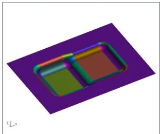
Figure 1 shows upper shell of real model of fuel tank. The initial blank size is 1800mm × 1400mm. It has the characteristic of thin material and large curvature of the fillet curve. During forming process, insufficient tension force on the majority area leads to wrinkles. To create enough plastic deformation, we should add supplementing material but too much supplementing material will cause cracks [7,8]. So to make a balance between crack, wrinkles and insufficient formation, an optimum value of arc radius of the fillet curve and thickness is needed to be determined. Analysis of this fuel tank model in AutoForm software will take much time for simulation because of complex shape of fuel tank. To make simulation process easy and efficient, this complex shaped fuel tank is replaced by a simplified fuel tank model. Figure 2 shows simplified fuel tank model. Figure 3 shows three values of arc radius of the fillet curve. Combinations of three values of arc radius (R) and thickness are to be analyzed for optimum value. These optimum values are determined with the help of Fractional Factorial Designs technique.
Kun-Cheng Chiu, Vijay Kumar Bharti, Shyh-Chour Huang
500
Figure 1. Upper shell of real model of fuel tank
Fig. 2. The simplied model of upper shell of the fuel tank.
Kun-Cheng Chiu, Vijay Kumar Bharti, Shyh-Chour Huang
506
3. Discussion
In industrial environment, there exist many criteria to decide whether a forming process is practicable and safe or not. In this paper the following most important criteria are considered to analyze simulation result:
-no cracks should occur (this is called crack criteria) -forming should wrinkle free.
The crack criterion is determined with the help of forming limit diagram. For reliable and safe forming process all the finite element point should fall below the forming limit curve (FLC).
Taking both criterions together, on comparing model-1, model-6 and model-7, we get that model-7 summarizes the result of the best simulation with optimized risk of the wrinkles less significantly in the part as can be seen by the formability plot. The wrinkling criterion is evaluated by formability diagram. Larger the wrinkle region (shown in the formability diagram) denotes there are more wrinkles. Analyzing the simulation results again on the basis of crack and wrinkle criteria, forming process in of the model-3, model-4 and model-8 do not meet crack criterion as points fall above the FLC curve and cracks formed are shown in the respective formability diagrams. Rests of models are safe against the crack as all the points are below the FLC curve but they should have minimum wrinkles. In formability diagrams, model which have least wrinkle region will be most reliable and safe.
So from the analysis, model which have large arc radius and small sheet thickness, in model-7, results a good sheet forming process without crack and wrinkling. As arc radius of the fillet curve reduces and thickness of the sheet increases results gets worst and they show cracks and wrinkles.
4. Conclusions
Arc radius and thickness of sheet has significant effect on the sheet metal forming process. As arc radius of the fillet curve is increased and thickness of the sheet metal decreased, fuel tank become more reliable and safe. Use of CAE system, AutoForm, to analyze a complex sheet metal forming problem has proven to be effective as a design analysis tool. Fractional Factorial Designs gives most necessary combinations of factors to be analyzed by reducing the number of experimental runs. It also saves the processing time and increases efficiency.
Reference
[1] Dong Hongzhi and Lin Zhongqin. Investigation of the sheet metal forming by numerical simulation and experiment. Journal of Materials Processing Technology, 103:404-410, 2000. [2] Feng Xu, Zhongqin Lin, Shuhui Li, and Weili Xu. Study on the inuences of the geometrical
parameters on the formability of stretch curved anging by numerical simulation. Journal of Materials Processing Technology, 145:93-98, 2004.
[3] Beom-Soo Kang, Bo-Mi Son, and Jeong Kim. A comparative study of stamping and hydroforming processes for an automobile fuel tank using fem. International Journal of
Study of the Effect of Arc Radius of Fillet Curve and Thickness of Sheet in Sheet Metal Forming 507
Machine Tool & Manufacture, 44:87-94, 2004.
[4] HP Schwefel. Evolution and optimum seeking. J.wiley and Son, New York, 1995.
[5] Olaf Schenk and Matthias Hillmann. Optimal design of metal forming die surfaces with evolution strategies. Computers and Structures, 82:1695-1750, 2004.
[6] AutoForm Engineering Inc.AutoForm-Incremental reference manual AutoForm Engineering Inc. 2003.
[7] Hongyang Qiu, Yajaun Huang, and Qiang Liu. The study of engine panel forming based on numerical simulation technology. Journal of Materials Processing Technology, 187-188:140-144, 2007.
[8] Ju Xiang and Pan sufeng. Sheet forming and its application. Auto Eng., 20(3):144{148, 1998. [9] R. C., Bose, S. S., Shrikhande, and E. T. Parker. Further results on the construction of mutually
orthogonal latin squares and the falsity of eulers conjecture. Canad. J. Math., 12:189-203, 1960.
[10] Jinn-Tsong Tsai, Tung-Kuan Liu, and Jyh-Horng. Hybrid taguchi-genetic algorithm for global numerical optimization. IEEE, 8:365-377, 2004.
[11] Jyh-Horng Chou, Shinn-Horng Chen, and Jin-Jeng Li. Application of the taguchi-genetic method to design an optimal grey fuzzy controller of a constant turning force system. Journal of Materials Processing Technology, 105:333-343, 2000.