85
High Throughput CORDIC-Based Systolic Array
Design for the Discrete Cosine Transform
Jue-Hsuan Hsiao, Liang-Gee Chen. Tzi-Dar Chiueh
andChun-Te Chen
Department
of
Electrical Engineering,Rm.
332
National Taiwan University, Taipei,Taiwan, 10764
R.0.C
ABSTRACTIn this paper, we propose a modified Malvar algorithm that can transfer the Discrete Hartley Transform (DHT) results to the Discrete Cosine Transform ( DCT) by using one additional CORDIC computing stage. A fast CORDIC-based systolic array is designed with four attractive features, including: 1) the singleldouble data folding feature; 2) the constructive feature; 3) the ca-computing feature; and 4) the redundant path computation. Due to the existence of redundant path, the proposed design also have capability of error detection.
1. INTRODUCTION
Due to the satisfactory perfonnance close to the statistically optimal Karhunen-Loeve transform, the Discrete Cosine Transform (DCT) is widely used in block signal coding for a wide class of signals. Fast algorithms for the DCT are, therefore, of significant practical interest. These algorithms can broadly be classified into three groups: I ) Direct Factorisation of the DCT matrix; 2) indirect computation through fast Fourier transfonn [FFT] or through Discrete Hartley transform PHT] 111; and 3 ) algorithms based on complexity theory.
However, by using direct or indirect algorithm to construct systolic array for the DCT transform has two drawbacks: 1) high memory bandwidth and 2) the difficulty of butterfly shuming between stages. On the constrary, the Discrete Hartley Transform was lately introduced as a new tool for the analysis, design and implementation of digital signal processing algorithms and systems. It is strictly symmetrical conceming the transform and its inverse. Applied it to real signals, it is faster than a real Fourier transform, especially in the case of the inverse transform. The speed of operation for a fast convolution can thus be increased. So, the DHT transform has been considered as an alternative to the FFT for spectral analysis and fast convolution of real data.
In this paper, we will present a new fast, parallel and high throughput systolic array design for the DCT computation, in which a DHT transform based on CORDIC algorithm is performed first, and then the result is passed through Hartley-to-Cosine transform.
2. CORDIC ALGORITHM
The CORDIC algorithm was first introduced by Volder [2] for the computation of trigonometric functions, multiplication, division, and data
type
conversion, and was generalized to hyperbolic functions by Walther [3]. The major advantage of this algorithm is given by the fact that it can be realized as sequence of additions /subtractions and shift operations. Since these operations are very well suited for VLSI realization, the algorithm has attracted a lot of attention in the recent times. For a detailed description of the CORDIC algorithm the readers are referred to Voldds and Walthefs original works.In the DHT computation, the elementaty trigonometric functions such as sine and cosine functions are involved. In order to facilitate these operations, the CORDIC will operate
in the circular coordinate system. Fig. 1 shows the rotation function computed by the C O m I C algorithm in this system. By setting x,, =A,, , yn = B p d Z, =
,
8
=(2n"), one can obtain B n* c os ( 2m /N )+A,,*sin(2m") from cordic-Y(m,n) and %*cos(2m")-Bn*sin(2K") cordic-X(m,n) concurrency. By using CORDIC technique, these two kernels can be simultaneously implemented in the same hardware. 3. THE COMPUTATION OF THE DCT TRANSFORM THROUGH DHT COMPUTATIONdefined as
The onedimensional DCT of N points, DCT(N), is
...( 1) where e(m) = if m =O; otherwise e(m) = 1. Since the factor fe(m) results only in a slight modification of C(m), it is sufficient to consider the DCT-like equation
...( 2) There are various schemes for computing 1-D DCT [I-31. Since the number of multiplications of the Winograd-Hartley transform is minimum, the DHT transform has adopted to calculate the DCT transform. In [4], a new data sequence
h,,
isdefined as
h,,
= ~ 2 . 1 ..
. . .(3) = ... . . .(4) N- I I F 0 C(m) = fe(m)C
x,cos[&(2n+
l)m], 0 1 ~ N- 1f i
N- IC(m)
=zo
X,COS[ &(2n+
l)m), OS m N - 1n = 0, 1, ... , N/2-1 n = N/2, ... N-1 and the DHT of
h,,
is defined aswhere cas(.) = cos(.) + sin (.). Combining Eq. (3) and (4),
N- 1
I F 0
U , =
c
h.cas(+" we obtainH,,, x . c u , ( ~ ) +
C
.xncus(-5(n+
1)) . ..
. .(5)
By using the identity cas(x)cas(y) = cos(x-y) +sin(x+y), Malvar has shown that
...( 6) and he has also proposed the following fast and parallel algorithm for computing the DCT transform through the DHT transform
odd
C(m) = i[H,cas(-%) + H ~ - ~ c a s ( G ) ]
. . . . (7) whqe m =0,1,2 ,..., N/2 and H, =
HN.
For our propurse, we define a css(.)= cos(.)-sin(.) function that has the following properties :cas(2rr
-
&m) = css(&m>, cas(:-
&m) = cas($m), and Moreover, we use these identitiesbelow
cas(^m - ;) = -css(&m).
lN
to simplify Eq. (7) as ...( 8) This formula indicates that let
X,
=Y,=H,,,
and Z,, =(md2N) at one CORDIC processor input ports,H,,,
cas(md2N) and css(md2N) will be obtained from output ports. In the same manner, let X,=Y,
=HN,
and Z,, =(md2N) at another CORDIC processor input ports, H,, cas(md2N) and I&, css(md2N) will be obtained from this processor. After this, one subtraction (H,,,
cas(md2N)- H,, css(md2N))86
and one shift right operation are proceeded to get C(N-m) result. Meanwhile, one addition (
H,
cas(mxL!N)+,
H
css(md2N)) and one shift right operation are also proceeded to get C(m) result. Therefore, an approach to high throughput DCT transform through the DHT transform will be achieved by using the CORDIC processor and Eq. 8.
4. A FAST SYSTOLIC ARRAY DESIGN FOR DHT The DiscreteHartley Transfonn (DHT) can be written as
N- I I F 0
H, =
c
h,cus(fmn)where m=O, 1,2,.
.
.,N- I and cas(. )=cos(. )+sin(. ) ... (9) There are four properties derived for 1-D DHT transform in [4]. They are: 1) the singlddouble data folding feature; 2) the constructive feature; 3) the co-compute betweenH,,,
and,
H
; and 4) the redundant path computation. We will briefly introduce these features in the following paragraphs.4a. The Data Folding
When
N=
2*x and x>=l, Eq. (9) can be folded as follows : NU-I F O N/2-I -0 H, = C [ ( h n +(-l)mh,+N~)cos($nl,f)]+
C [(hn+
(-l)ml~n+N/2)sin($mn)j N/2-l -0 = C [ ( / I n +(-l)mh"/2)cus($mrr)] N/2-I I F 0 =c
[ ( x h+
(-~)~x~-.zn-I>cus(fmn>l ... (10) FromEq. 10, one can also notice that the DHT of Npoints has been folded into N/2 points DHT to reduce multiplication and addition counts. This process is so called Single Data Folding (SDF). On the other hand, when N= 4*x and x>=l, Eq. (9) can also be folded as follows :N/4-I F O H, = C [Ampsin( fmn)
+
B,,cos( fmn)] Am, = [ ( / I n + (-l)mhn+N/2) i- (jIn+N/4 + (-l)mlln+3N/4)] = [(xh + (-1)"XN-2,-I) + (XZn+N/2 (-l)mxN&h-l)], when m mode 4 = 0,3 = [(hn+
( - l ) m h n + ~ ~ ) - ( h n + ~ / 4 + ( - l ) " h n + 3 ~ / 4 ) I = [(Xh +(-I)"xN-h-l)-(x2n+N/2 +(-l)mXN/2-2n-I)], when m mode 4 = 1,2. B m , = [ ( / I n+
(-l)mkn+N/2) + (ltn+~/4 + (-l)"hn+3N14)] = [(Xh (-l)mXN-%t-l) (x2n+N/2+
(-l)"xN/2-2n-l)]~ = [ ( l l , , 4- (-l)mlln+N/2)-
(hn+N/4+
(-1Y"1n+3~/4)] = [(xh + ( - l ) m X N - 2 n - l ) - ( x Z r r c N / Z +(-l)mXN12-2n-l)]r when in mode 4 = 0,l when in mode 4 = 2,3. also notice that the DHT of N points have been folded into N/4 points DHT to greatly reduce multiplication and addition counts. This process is so called Double Data Folding (DDF)4b. The Constructive Feature sub-summations :
Hk = { C [Ak+,sin($k(4n)) t ~k~,,cos($k(4n))l+ C = N/4.
Eq. 11
...( 1 1)
The folded
y
can be decomposed into four C/4-I F O c/4- I -0 c/4- I -0 C [Akh+~sin($k(4n +2)) +Bk,h+~cos($k(4n +2))]}+ { C [ A t h + , sin($k(4n+
1)) + B ~ . ~ , + I c o s ( $ ~ ( ~ N+
I))]+ c/4- I I F 0C
[ A~ ,, + ~i n ($ k( 4n +3)) +Bw,+~cos($k(4n +3))]) ...( 12)and the following identities
cordic-Y(m, n ) = cordic-CO - X(m, n) cordic-X(m, n ) = cordic-CO - Y(m, n )
can be used in H, to rewrite Eq. (12)
H, = {
C
cordic_Y(m,4n)+C
cordic_Y(m,4n+
2))+= A,,sin($nm) +B,,cos($mn) and = A,,cos($mn) - B,,sin($mn)
Cl4-I c14- I
tF0 n=O
c14-I c/4- I
I F 0 F O
{ C cordic_Y(m,4n
+
1)+ C cordic_Y(m,4n+3)) ...( l2a)c14- I c/4- I n=O I F 0 H,,,+N~ = {
C
cordic_Y(m,4n)+ C cordic_Y(m,4n+2)}- c14- I C/4-I I F 0 -0 c14- I c/4- I S O n=O { C cordic-Y(m, 4n+
1)+C
cordic_Y(m,4n+
3)) .( 12b) Hm+~/4 = { cordic-Y(m, 4n)- cordic-Y(m, 4n+
2)}+{'E'
cordrc-CO- ~ ( m , 4 n + I)-%' cordrc-co- Y ( m , 4 n + 3 ) } .(12c)R=O
c14- I c14- I
I F 0 n=O
H,,,+3~/4 = { cordic-Y(m, 4n)- C cordic-Y(m, 411
+
2)) -{'E
cordic-CO- Y(m,4n+ 1)-$I c o r d i c - 0 - Y ( m , 4 n + 3 ) ) .(12d) Eqs. (12a-12d) indicate that six constructive parts,c14- I c/4- I c14- I
I F 0 C cordic_Y(m,4n), I F 0 C cordic_Y(m,4n +2), I F 0 C cordic-Y
(m, 4n
+
I), F O C cordic_Y(m,4n+
3), F O C cordic-CO - Yc/4- I c/4- I
c14- I I F 0
(m,4n
+
1) and C cordic-CO-
Y (m,4n+
3) are used to construct H,,,,H,,,+,,,
kNn
.,and ,,+,,,H As the pair ofcordic-Y(mPn+l) and cordic-CO-Y(m, 4n+l) and the pair of cordic-Y (m,4n+3) and cordic-CO-Y (in, 411 +3) are mutual CO-result, they come out of the same computing hardware concurrently. Hence, only four parts of computing hardware are needed to construct them. Obviously, an four times throughput DHT transform will be achieved by using this constructive feature.
4c. The Co-computing between
H,
and H,,On
the other hand, HNmcan
be s h o m as follows :Cl - I n=O H N - ~ = {
k
[AN-n,hcos( $m(4n)) -B~-~.hsin($m(4n))]+ c14- I I F 0 c/4- I I F 0C
[A,+,,,,4m~cos($m(4n+
2)) -~N-,,4n+2sin(fm(4n +2))])+ { C [AN-,,~+I cos(%m(4n+
1)) - B N - ~ . & + I sin($m(4n+
I)))+C
[A~-m,h3~0~($m(4n+
3)) -B~-,++3sin($m(4n +3))]} c/4- II F 0
. .
.
.
.( 13a) By using the CORDIC technology to computeH,,,
, and we can find that{
C
cordic-CO-
Y(m, 4n)+ C cordic-CO-
Y(m, 4n+
2))+ { C cordic-CO-
Y(m, 4n+
1)+ C cordic-CO-
Y(m,4n+
3))...( 13b) This equatioil indicates that
H
,
,
can be constructed from the resultlco-result of K i n the same hardware. In the same can be constructed by the following six constructive parts-- HN-, =c14- I C/4-1
I F 0 I F 0
C14-l C/4-1
I F 0 I F 0
way, we find that HN,, HN.(mt3N/4)r H N . , N / ~ ) and HN.(,,,+Nn)
c14-1 c14- I
n=o I F 0
e/& I c/4- I
I F 0 -0
C
cordic_Y(m,4n), C cordic-Y(m, 4n +2),87
Cl4- I Cl4- I
I)=o C cordic_Y(m,4n
+
l), and I F 0 C cordic_Y(m,4n+3). Andthese six parts are also existing when we construct
H,,,,
H,,,+",
Gw
and&,,. Thus, no additional computing efforts are required to construct them. It means that the throughput can beimproved by eight times.5.
THE
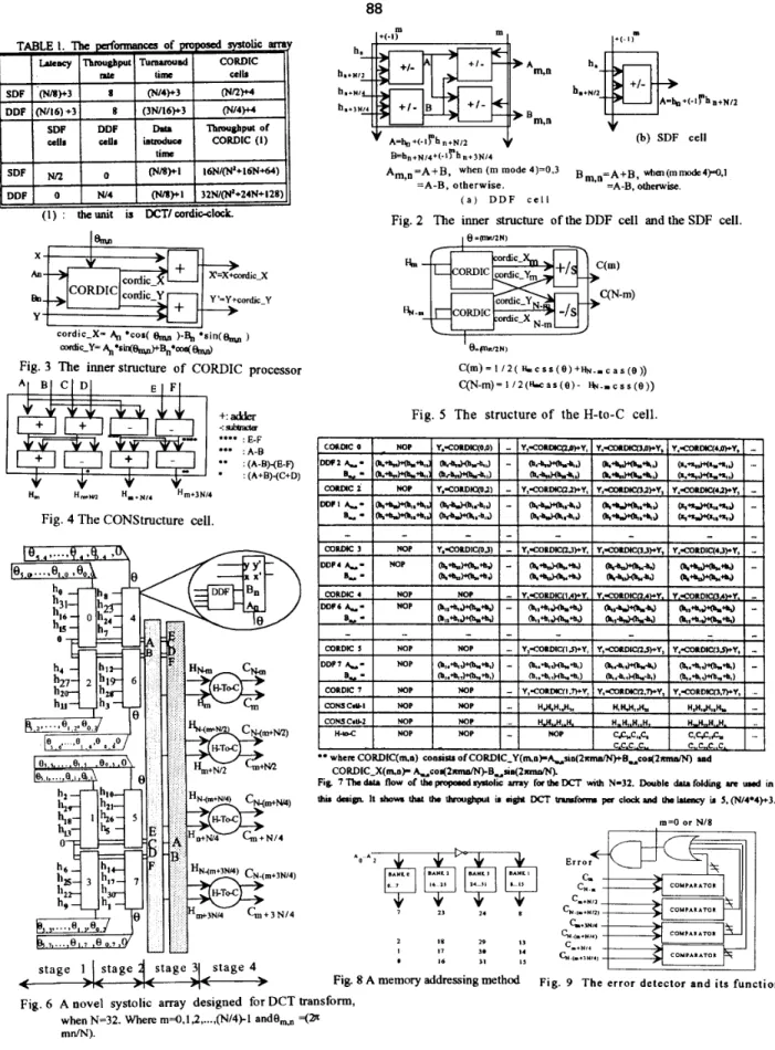
PROPOSED SYSTOLIC ARRAYAs noted in Eq. (8), each C(m) can be realized by the construction of CORDIC computing terms by data folded and modified Malvar calculation. There are totally four tasks to achieved the DCT, including data folding, DHT kernel computing by CORDIC processor, DHT constructing and DHT-to- DCT conversion. Four different cells are proposed to do these computations. First, the SDF(DDF) cell is designed to implement the data folding task. Fig. 2 shows the inner structure of SDF and DDF. Second, the CORDIC processor is developed to compute the DHT transform. The structure of the CORDIC processor is shown in Fig. 3. Third, a CONStructure cell is shown in Fig. 4. One CONStruture cell guided by Eqs. (12a-12d ) can be used to construct
H,,,,
kNn
and QjNI4 and another cell guided by Eqs. (13a-13b)Finally, Fig. 5 shows the H-to-C cell designed for completing DHT-to-DCT conversion.
By using these four cells types and their features, a novel systolic array for the DCT can be obtained. Fig. 6 shows the proposed architecture with N= 32. Since N=4*4*x, the DDF cell is used to do single data folding before CORDIC computing and then followed by the CONStructure cells to get eight DHT transform results. These results are sent to H-to-C
cells to obtain the exactDCT results.
The data flow of the proposed systolic array for the DCT computation are shown in Fig. 7. At clock 1, every DDF unit in stage 1 calculates
4,
and B,, and then the results are sent to the following CORDIC unit in the next stage for CORDIC-X(mp) and CORDIC-Y(m,n) calculation at clock 2. Meanwhile, new DDF computing is going on. The arrow points out the direction of the data flow. After the clock 4, the DHT transform results of&,
H,, H,, and H, are obtained from the CONStructure cell-1 and another four DHT transform results of&,
%,
H,, and&
are obtained from the CONStructure cell-2. From this, another eight DHT transform results per clock will be achieved. Therefore, this proposed systolic array can get eight DCT results per clock after the latency. In other words, the proposed array can achieve eight times throughput compared with other previous works. The latency consists of four parts : one data folding clock, stage clocks ,one result constructive clock and one H-to-C conversion clock. Incidentally, the stage clocks for computing each constructive part ofH,,,
can be represented as :stage clocks = N/(data folded factor
*
constructive factor) where data folded factor = 2 , for single data folding and= 4 , for double data folding.
can be
used to construct HN.m, HN.(m+N/4)9 HN.(m+Nn) and HN.(m+3y4)'constructive factor = 4
Fig. 8 indicates an addressing method on four-bank memory that is shown in Fig. 6. According the data flow in Fig. 7, the data introduce time is 5 clocks, and this time can be formulated as (N/8)+ 1.
Because the redundant path computations exists, an error detector has been design for the hardware failure detecting. Fig. 9 shows its inner structure and illustrates the
hardware error Occurrence on C(N-m)# C(m),when m=O and m=N/8.
6. THE ANALYSIS
OF
COMPLEXITYSuppose a conventional CORDIC processor requires TcoRDlc = nT, time to complete the computation, here n is the number of CORDIC iterations, Tc=TM+Td is the time of one CORDIC iteration and T,,
+
Td are the shift and addition operations, respectively. Therefore, every CORDIC unit needs Tcoms+Td to complete the computation ofh,
cos(O,,J+h&O,) and h,cos(0,) -h,sin(O,,,,,).
In order to enchance the throughput of the DCT, the pipelined design will be considered to meet this requirement. The performances of proposed systolic m a y are listed in Table 1. The throughput rate is defined by the number of the DCT transformation in one clock. In our proposed systolic array, the latency can be formulated as (N/2*4)+3 [ (N/4*4)+3 ] clocks for the SDF P D F ] mode, and the throughput rate is eight DCT transforms per clock. The turnaround time represents the total clocks needed to complete the whole DCT. The data introduce time indicates the time between two N data sequencies. Another measurement, shown in the last term, is the throughput of the CORDIC unit. It can be defined as follows:
N D C r
nroughput Of CoKDIC =(Doto " d x e rimWwnbcrofCORDlC used)
The unit of the last term is DCT I cordic-clock. In our proposal, the tluoughput of the CORDIC in the SDF P D F ] mode is 1 6N/(N2+ 16N+64) [ 32N/(N2+24N+ 128)].
7. CONCLUSION
In this paper, we have derived a modified Malvar algorithm to meet the CORDIC based requirements and used it to get the DCT results via
DHT
computation. The transfomng is only to permute the input sequences and append one CORDIC stage to the DHT systolic array. Thus, a high throughput and cost effective architecture has been designed for the 1-D DCT. Almost eight times performance can be obtained, while much cheaper hardware is implemented. Moreover, this design can provide error detection capability. Due to its regularity and simplicity, the proposed architecture will be very suitable for VLSI implementation.8. REFERENCES
[ 11 H. Malvar, " Fast computation of discrete cosine transform
through fast Hartley transform ," Electronic Letters, 1986, Vol. 22, NO. 7, pp.352-353.
121 J. E. Volder, " The CORDIC trigonometric computing
technique,"
IRE
Trans. Comput., Sept. 1959.functions," in M I P S Spring Joint Comput. Conf., 1971, [4]J. H. Hsiao, L. G. Chen, T. D. Chiueh and C. T. Chen, I'
Novel systolic array design for the discrete Hartley transform with high throughput rate," Proc. of JEEE International Symposium on Circuits and Systems, ChicagoJllinois, pp. 1567-1 570, May, 1993.
Vol. EC-8, pp. 330 -334, [3]. J. S. Walther, " A unified algorithm for elementary
pp.379-385. cordic_X(mn) = X& 7.dY *n( 2.J cadic-Y(mn)
-
X.amtz-pY.ca( LJ z , - 0" " g = E
2"88
DDF 0
[
W4I
(")+II
3ZN/(N*+24N+IZB)I(1) : theunit is DCTlcordic-clock.
cordic-X-
4
*COB(&,
)-€$, *sin(% )d c - Y - . 4 , , * s ~ & ) + B n * ~ ~
Fig. 3 The inner structure of CORDIC processor
+:adder -: s l b a f r **** : E-F *** : A - 8 ** : (A-B)-(E-F) * : (A+B)-(C+D) H, H i m "m+JNN
Fig. 4 The CONStructure cell.
(b) SDF cell B ' h n + N / 4 + ( - l y h n+3N/4
A,,,=A+B, when (m mode 4)=0.3 B,,,=A+B, ~~1en(mmocie4)-0,1
=A-B, otherwise. =A-B, otherwise.
( a ) D D F c e l l
Fig. 2 The inner structure of the DDF cell and the SDF cell.
I fl =illR/ZNI
Fig. 5 The structure of the H-to-C cell.
2 I 8 29 1 3 I 17 3@ I4
a 16 3 1 I 3
Fig. 8 A memory addressing method
1
Fi g. 9 The error detector and its function.
Fig. 6 A novel systolic array designed for DCT transform,
when N=32. Where m=0,1,2 ,..., (N/4)-1 andO,,n =@