Proceedings of the 2004 IEEE
lntemational Confcrcnce on Control Applications Taipei, Taiwan, September 2-4,2004 ' I4.
An Air Combat Simulator in the Virtual Reality with the
Visual Tracking System and Force-feedback Components
Cheng-Ming Hnang', Su-Chiun Wang', Chih-Fu Chang', Chin-I Huang', Yu-Shan Cheng', Li-Chen
Fu',*
Department of Electrical Engineering
'
Department
of
Computer Science and Information Engineering*
National Taiwan University, Taipei, Taiwan, R.O.C.E-mail: lichen@ccms.ntu.edu.tw
Abstract
-
This paper presents a new multi-plane air combat simulator based on the visual servo ,system. The scenario is an air combat of twofighters in virtual reality The escaping o m is simulated by a Stewarlplafform with a force-feedback joystick, overall controlled by a human operator The chaser is rcalized as a visual servo sy.ytem.a.s i/ the simulated air fighter were equipped with a
militaty Iight-o/-sight (LOS) to lock on tu the mentioned escaping air fighter Specifically, any arbitrarpshaped object that appears on a screen refecting the virtual space of the escapingfighter can be automatically detected and locuted by the visual syvtem in real-time so that the 2-DOF camera simularing LOS can be controlled due to visual servo to keep the target object cenlered in the camera image. By sensing the morion of the cameraplatfom, the autopilot qf the chasingfighter tries to/ollow he escaping one as closely as possible with an aim of shooting it down. The overall s y t e m is experimented in a virtual reality environment to validate the underlying research work. A promising application of this setup is to evolve into an
entertainmentfacility or a military trainingplafform. Keywords: visual tracking, visual servo, virtual reality.
1
Introduction
Visual tracking has been an important topic in computer vision and robotics fields. For practical visual tracking systems, there arc some basic functionalities required: real-time, automatic, and robustness in non-ideal situations, such as occlusions and cluttered environment. Surveys show that individual problenls mentioned above have been solved. For example, CONDENSATION algorithm [ 5 ] is highly regarded since it solved both the real-time and the robusmcss problems, hut not the automatic one. Up to now, to the hest of our knowledge, thcre is no literature addressing all the problems. Thcrefore, an integratcd algorithm is presented in this paper to overcome the overall problems mentioned above by combining tcmplate matching [10-12] and Snake-hased
counter matching [I-3, 13-14], The proposed algorithm also improves the disadvantages of classical Snake [I-31. The traditional Snake algorithm has two major disadvantages. One is about that the poor initial contour
[I51 will fail to converge to the desired global contour feature. The other one is about the low convergent spccd, so it is seldom applied in visual servo problem.
On the other hand, virtual reality (VR) is a kind of
advanced tcchnology which facilitates scientists and engineers to simulate and to verify their works in an interactive application environment. Apparently, unmanned air vehicle (UAV) experiments posc really challenging environments for various related conduct researches [9]. Owing to this condition, before performing that real experiment, this paper proposes a multi-plane simulator which integrates the visual tracking algorithm and the VR presentation technique so that a UAV equipped with a visual tracker can he tcsted in lab.
This paper is organized as follows. Scction 2 describes the functions of the subcomponents of the visual tracking system for tracking arbitrary-shaped moving object in the low-contrast environment, even there are some shelters. Section 3 presents the visual servo application of the UAV air combat in the virtual rcality. Section 4 shows some experiment results, and Section 5
gives some conclusions.
2 Visual Tracking System
Thc architecture of our visual tracking system can hc hricfly shown by the block diagram in Fig.1. It consists of four subsystems, including motion dctection, Snake-based outline extraction, hybrid tracking algorithm, and visual probability data association (VPDA) filter. The on-line image scquences are grabbed by a camcra, which is mounted on a pan-tilt servo platform. In the beginning, the camera platform is stationary. When a moving target appears in the detecting screen image, the motion detector will starts the systcm. The Snake-based outline extraction is used to find out the target position and size in the image.
Wc always keep the target in the center of the screen image by moving the 2-DOF camera platform. The visual servo system will correct the errors from the image information fccdback of the visual tracking systcm. The hybrid-based tracking algorithm does the image processing to find out the target in each captured image frame. Since the target may keep on moving during the processing time between the image framcs, we use the VPDA (visual probabilistic data association) filter to estimate the future position of the target. The VPDA filter also can increase the robustness and reliability of our tracking system by considering several similar image processing results of the hybrid-based tracking algorithm. Finally, the estimated target position will be transformed to adjust the pan and tilt rotation angles of the camera platform motors. If the system is lost tracking, it has homing ability to restart the system. Othenuise, it will keep on tracking in the right loop in Fig. I
I
Fig. 1. The architecture of visual tracking system
2.1
Motion Detection
There are several advantages of using motion detection heforc tracking an object. First, it provides important clues to an automatically tracking system. If a moving object enter the camera view field, the motion detector will detect some differences between two consecutive frames and start the system. Second, we can determine a smaller searching range to reduce the computation time offinding out the position of the moving object in the image, obtaincd by motion detection with a stationaty camera. Third, the scgmentation of the moving object can be the basis for automatic initialization of Snake.
First, two consecutive image frames
Z(k)
andI ( k
-1)
are subtracted pixel by pixel, and the absolute values of the results are then binanzed. If the total number of white pixels is less than the threshold, the motion detection unit continues to examine thc next two consccutivc frames. On the contrary, if the numberexcccds the threshold, it means that there is a target to be detected. The concept of "moving edge" is included by doing a logic AND operation between the subtracted image and the edgc image of the current frame. We can yield a more accurate image position of the target outline from the moving edge image. Finally, since we have known the approximate size and position of the moving target from the moving edge image, the moving cdgc image is submitted to generate a proper-sized initialization of Snake for outline extraction, which is detailed in next section.
2.2
Snake-Based Outline Extraction
The objective ofthe section is to extract the outline of the target by active contour models (also called Snakes) [I]. A modified Snake is presented here on the basis of the Greedy algorithm [ 2 ] . The proposed Snake defines a force constraint to speed up the convergence to the desired feature of the object, and provides an easy way to avoid the wrong convergence on a local noisy point. If
V , =
(xj,y,)
fori
=0,1,
...,
N
represents theN
-
length discrete contour, the modified Snake energy isN
=
1
{a,EcYln, ( v , ) +b,~,,.(v,)
+YJ,
( v , ) +I
/ i l
where
E<"",
is the continuity energy,ECu,"
is curvature energy,E,
is the image energy andEd,*
is the constraint energy, called distance energy. The parametersa , ,
p,
,y,
and7,
are used to adjust the relativeinfluence of the four terms. The four energy terms are defined as
E m =
E',,,, =
w ~ { l v , - , - 2 v , ( i ) + v , + ) r }
where
d
is the average distance betwwecn contour pointsv,
, andvj
( j )
reprcsents the eight neighbors of a pointv,
forj
=l , , , . , 8
.
Moreover,vZ(v,)
denotes the image intensity of the cdge image at current position,the current position and the center of the object; and
VI,,
(Om,, ) and VImin(Om,
) denotc the maximum and minimum image intensity (distance from the center of the object) in thc neighborhood, respectively. The moving direction of the Snake can he decided by adding or subtracting the distance energyThe concept of Greedy algorithm [2] is to take minimized as the sum of the minimized values
E,,,,
(v;)
for each individual point in the contour, that is(3)
/=1
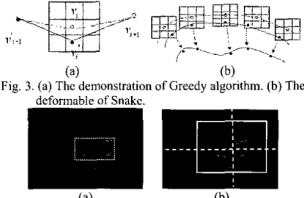
Figure 3(a) demonstrates how the iterative Greedy algorithm works. The cnergy function is computed for the current position V, and each of its neighbors. Then, tbc location having the smallest energy value is chosen as the new position
v,'
.
As a result of repeating the aforementioned process point by point, all points of the contour keep moving fonvard to their Corresponding new positions to form a new contour. Throughout the processes, the Snake completes an iteration of the deformation loop. The Snake will repeat thc deformation loop iteratively until it converges to the desired feature of the object. as shown in Fig. 3(h).From the result of motion detector, a moving object is detected. Assume the whole body of the object is completely inside a 140x140 area, which is the searching area. We choose a proper-sized ellipse, which can enclose the wholc moving ohjcct inside, as an initialization of Snake. The centcr of ellipse is located at the center of the bounding box that contains the object inside. As shown in Fig. 4, we also use the center of the minimized rectangle as that of the searching area of the hybrid tracking algorithm.
(a) (b)
Fie. 3. (a) The demonstration of Greedv aleorithm. (h) The
(4
(h)Fig. 4. In moving edge image, (a) the bounding box of the object, and (h) is thc searching area and its centcr.
2.3
Hybrid
Tracking
Algorithm
Different from the traditional Snake-based tracking algorithms [3-10], Snake is only used to extract the outline of the target rather than to perform tracking in OUT system.
Since Snake-based Cracking algorithms should be under the assumption of slowly moving object, it is failed in tracking the object with large movement. This paper presents a contour matching method which makes use of the extracted contour model for tracking an arbitraw-shaped object. But the method also has a restriction against low-contrast environment, just like what the Snake-hascd tracking algorithms encountered. Hence, we integrate the most commonly used method in visual tracking, called template matching, with contour matching to overcome the foregoing drawback.
We use the SAD (sum of absolute difference) criterion for template matching:
where
s
=(x,
y ) represents the position of the center of template model,I ( x + m , y + n )
is the current searching image values, andI,(m,n)
is the referenced template imagc values with sizeB
xB
.The details ofcontour matching are described as follows. To highlight the contour of an object in an image, the edge image is used for object tracking (see Fig.5). Similar to template matching, we need to sum the total gradient values pixel by pixcl in the edge image along a pre-extracted Snake contour model. After summing over a contour model, we will shift the center of contour model to the next pixel and compute the summation along the perimeter of the contour model again. After going through all the searching area, we can get the largest summation corresponding to the distribution of edge pixels which resembles the object's contour. The numerical process in each searching loop mentioned above can be summarized by the following normalized sum equation
where s = (x,
y)
represents the position of the center of contour model.No
is thc total number of all pixels along the perimeter of contour model, andg,
denotes the gradient value of each pixel along the perimeter of contour model. Hence, thc best object position is considered to combine eq. (4) and eq. ( 5 ) as( 6 )
i, rsr where
are the normalized forms, in which 8 , is the center position of the contour model as well as the template, and
sr
is the searching area.2.4
VPDA Filter and Trajectory Design
Highly cluttcrcd environment may contain many background contents that are quite similar to the target and then result in false alarms, which may cause further error accumulation in the subsequent tracking. Not only a had template or contour will be involved, but also the trajectory detection will be misled. Furthermore, it will seriously affect the position of the searching window. Thus,
it gives rise to a high possibility
of
lost of tracking once the best match is a false match. For this reason, VPDA is adopted to overcome the challenge in the cluttered environment. It can providea
more reliable approach to predict the next position of the target and enhance the robustness of the tracking system, even in the cluttered environment. Actually, the VPDA filter is the original probabilistic data association (PDA) filter [7] integrated with the visual information, introduced in[XI.
The concept of thc PDA filter is to take all possible targets into account instead of only the best matched one that may be correspond to a part of the cluttered environment. Finally, it produces a weighted-average output from all possible candidates. The method applied for computing the weights is probabilistic. It computes the posterior association probabilities for all current possible candidate measurements and uses them to form a weighted sum of innovations for updating the target’s state in a suitably modified version of thc Kalman Filter.
3
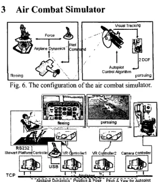
Air Combat Simulator
Fig. 6. The configuration of the
air
combat simulator.Fig. 7. The architecture of the overall system As has bcen mentioned in introduction, thz hereby proposed visual servo algorithm is taken to build a virtual reality system involving UAV which allows simulstion and evaluation of the control performance of some UAV equipped with a visual tracker. As shown in Fig. 6 and Fig. 7, there are two air fighters in the virtual reality environment. The challenge is that the tracking path of the UAV is dynamically changing, not
a
regular cruising or off-lined designed one. On the other hand, the UAV is experimented in the VR, however, our visual tracking system and the force-feedback system is constructed in the real world. There must he complex coordinate transformations and relationships between each subsystem. The fleeing one is operated through force-fccdhack joystick by the pilot who sits on a steward platform. he force-feedhack system utilizes the motional Stewart platform and the force-feedback joystick to express the real force feeling of the pilot with respect to the real airplane dynamics. The force-feedback joystick is 3 DOF with 2 DC motors and throttle. Our Stewart platform has the features of the high accuracy servo valve with higher control bandwidth to offer rapid response and high power to payload weight ratios. With the highly nonlinearity actuators combining with dynamic platform model, the backstepping adaptive control law.The pursuing one is mounted with the visual tracking system as mentioned above. We want to emphasize that the visual tracking system hcrc is to play the role as a militaty
light-of-sight to lock on the target. Also, we can use the pan and tilt information of the camera to aid the autopilot of the pursuing air fighter. In other words, the visual tracker of the pursuer in the virtual world will he replaced hy the camera mounted on a motion platform, and the VR image will he presented from the viewpoint of the pursuer so that the visual servo system can successfully fulfill its endowed function. Each subsystem communicates with one another through TCPilP protocol.
4
Experimental Results
The performance of the Snake-based outline extraction is quite appealing and very fast even if the object appears in highly cluttered environment, as shown
in Fig. 8. In Fig. 8, the dashed contour curve describes the contour matching, the small rcctangle shows the template matching, and the large rectangle is the search range. Figure 9 and 10 demonstrate tracking of a moving tank model and a VR target, rcspcctively. In the VR autopilot case, we can see that the fleeing one is chased by the pursuer, as shown in Fig. 11 (a) and (b), from the viewpoint of the pursuer. Experimental results show that our tracking system is highly robust against occlusion, low-contrast environment, and rapid motion. Figure 1 l(c) shows the flceing airplane and the force-fecdhack components.
5
Conclusions
The contribution of this work is to establish a multi-plane simulator based on an integrated visual servo system. The overall system integrates the visual tracking, virtual reality, force fccdback, network communication, and robotics. Thc major component is the visual servo system, which can track an arbitrary-shaped object in a highly noisy environment, cvcn with some occlusions on the target. The visual tracking system can pcrform the tracking processes with 320x240 image size in nearly real-time constraint (less than 34 ms) and center the target up to 15-pixel square range tolerance. We also improve the Snake model, the visual tracking method with a hybrid tracking method, and the VPDA filter. The simulator can further bc developed as an entertainment or military training platform
References
[ I ] M. Kass, A. Witkin, and D. Terzopoulos, “Snakc: active contour models,” Int. J. Comput. Vis., Vol. 1, pp. 321-331, 1987.
[Z] D. J. Williams and M. Shah. “A fast algorithm for active contours and curvature estimation,” CVGIP: Image
Understanding, Vol. 55,No. I , pp. 14-26, Jan. 1992. [3] C. Xu and J. L. Pnncc, “Snakes, shapes, and gradient vector flow”, IEEE Trans. /mage Pmcessing, Vol. 7, No. 3, pp. 359-369, 1998.
[4] J. Denzeler and H. Niemann, “A two stage real-time object tracking system,” In Pave.yi‘c et al.
[ 5 ] M. Isard and A. Blake, “CONDENSATION- conditional density propagation for visual tracking,” Int. J.
Computer Vision, pp. I-36,1998.
[6] J. Denreler and H. Nicmann, “A new energy term combining Kalman filter and active contour models for object tracking.” Machine Graphics Vision, Vol. 5(1/2), pp.
157-165, 1996.
[7] Y. B. Shalom and E. Tse, “Tracking in a cluttered environment with probabilistic data association,” Automatica, Vol. 1 I , pp. 451-460, 1975.
[SI D. Liu, “Real-time visual tracking in cluttered environment with a pan-tilt camera,” Masler Thesis, Dept. of E.E., National Taiwan University.
[9] A. H. Gaktogan, E. Ncttleton, M. Ridley, and S. Sukkarieh, “Real time multi-UAV simulator,” Proc. ZEEE ICRA, pp. 2720-2721,2003.
[IO] R. Brunelli and T. Poggio, “Templatc matching: matched spatial filters and beyond,” M T AI Memo 1549, July 1995.
[ I l l M. S. Lew, N. Suhc, and T. S. Huang, “Improving visual matching,” IEEE Conference an Computer Vision and Pattern Recognition, Vol. 2, pp. 58-65,2000,
[I21 Y. S. Chen, Y. P. Hung, and C. S. Fuh, “A fast block matching algorithm based on the Winner-update stratcgy,” Proc. of the 4th Asian Conf on Computer Vision, Vol. 2, pp. 977-982,2000.
[I31 S . Birchfield, “An elliptical head trackcr,” 31”‘ Asilomar Conference on Signal, Systems, and Computers, November 1997.
[I41 S. Birchfield, “Elliptical head tracking using intensity gradients and color histograms,” IEEE Conf on Computer Vision and Pattem Recognition, Santa Barbara, Califomia, July 1998.
[IS] C. Han, S. Hatsnkami, J. N. Hwang, and C. Yuan, “A fast minimal path active contour model,” IEEE Trans. Image Processing, Vol. 10, No. 6, June 2001.
(a) current image (b) initial contour (c) extracted outline
Fig. 8. It takes only 9 itcrations between
(b)
and (c) to extract the tank's outline with 84 pixel-length of initial contourFig. I O . Tracking the air fighter in the various VR er
-
fleeing joystick
-
Fig. 11. (a) and (b) The autopilot ability shown from the viewpoint ofthe pursuer. (c) The pilot and the force-feedback components of the fleeing air fighter.