New Sediment Bypass Schemes in Sakuma
and Yahagi Dams in Japan
Tetsuya Sumi
Abstract
Sediment routing is one of attractive sediment management schemes to route incoming sediments to the tailwater without settling in the reservoir. In sediment routing, various effective techniques can be applied: direct bypassing around the dam using tunnels or channels, diverting to an off-channel reservoir, and passing sediments through the reservoir by either sluicing or turbidity current venting. Sluicing requires a partial water level drawdown to transport incoming and to some extent accumulated sediments to the dam outlet structure, whereas venting of turbidity density currents can be performed without lowering. Sluicing includes both bedload and suspended sediment, whereas venting is only possible for the latter.
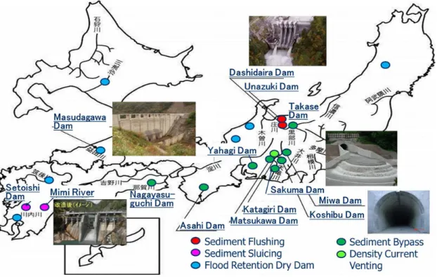
In Japan, several leading projects have been started to operate or under planning. Dashidaira and Unazuki dams are a unique example which is implementing coordinate drawdown sediment flushing. As to sediment sluicing, Saigo and Ouchibaru dams in Mimi river are newly started to implement coordinated sediment sluicing. Upgrading of spillway gate will be finished soon at Yamasubaru dam to start coordinated sluicing in these three dams. Sediment sluicing operation has been also started at Setoishi dam in the Kuma river. As to sediment bypassing, Asahi (1998), Miwa (2005), Koshibu (2016) and Matsukawa (2016) are good examples. After them, Yahagi and Sakuma dams are listed as the next sediment bypassing projects. Additionally, Nagayasuguchi dam and Takase das and others are under planning. These projects are listed in Figure 1.
Multipurpose Yahagi dam operated by MLIT is an arch type dam completed in 1970 with H=100m, A=504.5km2 and V=80MCM. Historically, this dam is receiving large volume of sandy sediment from granite upstream catchment. Hydro dredging has been conducted to keep active storage volume which provides suitable sandy sediment for construction materials. In 2000, heavy torrential rainfall delivered huge volume of sediment which accelerated sedimentation speed and then, MLIT organized technical committee to solve this issue. For making master plan, various aspects have been discussed such as 1) Target sediment volume, 2) Advantage points comparing with other conventional techniques, 3) Design discharge of the tunnel, 4) Intake and outlet position and total length of the tunnel considering Yahagi No.2 dam and 5) Sediment intake facilities such as conventional open channel or hydro-suction. After various discussions, we have recently concluded that inlet of sediment bypass tunnel is located upstream of reservoir area and guided to downstream of Yahagi No.2 dam which is
compensation reservoir of Yahagi dam. Tunnel layout is shown in Figure 2. Hydraulic model tests and other detailed studies are implemented.
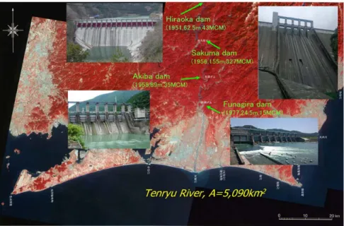
Sakuma dam operated by J-Power is a concrete gravity dam completed in 1956 with H=155m, A=4,156.5km2 and V=326.8MCM. This dam is located mainstream of the Tenryu River and a key infrastructure in the cascade hydropower scheme (Figure 3). At the same time, Sakuma dam is receiving huge volume of sediment from upstream river basin with high mountains passing alongside tectonic fault. Grab dredging and barge transportation has been conducted to keep sedimentation profile in order to prevent artificial flooding on upstream local residential areas nearby river channel. From the beginning, part of dredged sediment has been used for construction material. Another part has been dumped in deep dead storage volume. In 2009, MLIT has started upgrading project of Sakuma dam to add both flood control and sediment routing functions. Sediment routing in cascade dams including Sakuma dam is very much important for integrated sediment management plan in the Tenryu River Basin especially for mitigating severe coastal erosion. In order to maximize these objectives, MLIT organized technical committee to select feasible routing techniques for Sakuma dam because its reservoir length is very long more than 30km. For making master plan, various aspects have been discussed such as 1) Target sediment volume, 2) Comparing long and one-line SBT or other combining techniques such as barge transportation and short SBT, 3) Sediment intake facilities such as hydro-suction or conventional grab dredging. Figure 4 shows several sediment routing options through Sakuma and Akiba dams at the beginning stage. After various discussions, we have recently concluded to combine grab dredging, barge transportation, short SBT with conveyor belt and sediment stockyard below dam. Flood flow will be guided to the stockyard to naturally erode sediment to the downstream river as a large scale sediment replenishment. Schematic diagram is shown in Figure 5. Hydraulic model tests and other detailed studies are undergoing. Akiba and Funagira dams will implement sediment sluicing operation to minimize sediment deposition in each reservoir area.
Keywords: Sediment Bypass Tunnels, Yahagi Dam, Sakuma Dam
Authors
Tetsuya SumiWater Resource Research Center, Disaster Prevention Research Institute (DPRI), Kyoto University, Japan
Figure 1 Advanced Project on Reservoir Sedimentation Management in Japan
Figure 3 Downstream area of the Tenryu River and cascade hydropower dams
Figure 4 Several sediment routing options through Sakuma and Akiba dams