國
立
交
通
大
學
電機學院微電子奈米科技產業研發碩士班
碩
士
論
文
以Nafion
TM/PR包埋結構作為參考場效電晶體之感測層研究
The study of Nafion
TM/PR entrapment structure as REFET sensing film
研 究 生:陳明聰
指導教授:汪大暉 教授
以Nafion
TM/PR包埋結構作為REFET參考場效電晶體感測層之研究
The study of Nafion
TM/PR entrapment structure as REFET sensing film
研 究 生:陳明聰 Student:Ming-Cong Chen
指導教授:汪大暉 Advisor:Ta-hui Wang
國 立 交 通 大 學
電機學院微電子奈米科技產業研發碩士班
碩 士 論 文
A ThesisSubmitted to College of Electrical and Computer Engineering National Chiao Tung University
in partial Fulfillment of the Requirements for the Degree of
Master in
Industrial Technology R & D Master Program on Microelectronics and Nano Sciences
Feburary 2008
Hsinchu, Taiwan, Republic of China
以Nafion
TM/PR包埋結構作為REFET參考場效電晶體感測層之研究
學生:陳明聰
指導教授
:汪大暉 博士
國立交通大學電機學院產業研發碩士班
摘
要
離子場效電晶體(Ion-sensitive Field Effect Transistor,ISFET)是由 Bergveld 在 1970 年提 出,因其元件的特性尺寸小,反應速度快、可承受外部應力,且相容於現今的 CMOS 製程相 容性,所以在現今的感測元件開發中具有極大的潛力。在微小化的技術上,必須要整合一個固 態參考電極在 ISFET 上,然而先天上固態電極的金屬/溶液接面電位不易穩定,使得研究方向 朝向開發參考電極場效電晶體(Reference Electrode Field Effect Transistor,REFET)。 REFET 本身是一個低靈敏度的 ISFET,利用一差動放大量測電路來抑制未經處理之金屬固態電極造成 的不穩定參考電位。 為得到一個低靈敏度的ISFET,本篇論文中以利用一質子交換膜NafionT包覆PR(FH6400) 的結構來完成一個REFET,成功的降低了感測層對離子的感測能力,從未包覆前的 57.5mv/pH 降至 8mv/pH。此外,本實驗還利用二氧化鋯(ZrO2)和二氧化矽(SiO2)兩種不同的感測層當基 底,探討Nafion包埋PR結構降低了對氫離子感測靈敏度的機制與基底材料之間的關係。最後, 再利用不同Nafion包埋PR條件來做pH1~pH13 的靈敏度(sensitivity)和漂移(Drift)量測,並研究 其元件特性的重現性及可靠度。 我們成功地以NafionTM包埋PR結構完成對氫離子感測靈敏度的降低,從實驗結果得到其感 測靈敏度從未包覆前的 57.5mv/pH降至 8mv/pH。目前推論其靈敏度的降低主要來自Nafion所 包埋的PR所致,與下層所疊的材料無直接的影響性,且在Nafion混合PR的結構所製作出REFET 的感測層可維持在一個穩定且固定的電位且不受外部的離子所影響,由實驗值得到在四小時內 的漂移(Drift)量相當穩定。
The study of NafionTM/PR entrapment structure as REFET sensing film
student:Ming-Cong Chen
Advisors:Dr.
Ta-hui Wang
Industrial Technology R & D Master Program of
Electrical and Computer Engineering College
National Chiao Tung University
ABSTRACT
Ion-sensitive Field Effect Transistor, ISFET is proposed by Bergveld in 1970 since its feature of the component is small size, rapid response, strong robustness and be acceptable to the process of CMOS nowadays, it has the great potential on the development of nowaday’s sensitive component. It has to integrate a solid state reference electrode on the miniaturized technology. However, the metal of solid state reference/electrolyte is not to defined, so the direction of the research moves toward developing Reference Electrode Field Effect Transistor, REFET, which is a low sensitivity ISFET itself using a differential amplifier measuring the circuit to set off the unstable voltage caused by the metal solid state without handling.
For attaining a low sensitivity ISFET, this academic essay utilizes the structure of proton exchange membrane. Nafion entrap with PR (FH6400) to finish a REFET which successfully reduce the sensitivity to 8.3mV/pH. Moreover, this experiment use ZrO2 and SiO2 the two different sensing film as the base to discuss the relationship between the mechanism that the structure of Nafion entrap PR reduce the sensitivity to H+ ion and the base material. At the end, it also measures the sensitivity of pH1 to pH13 and Drift on the condition of different Nafion entraps PR and research the repeatability and reliance of the component’s feature.
We finish successfully the reduction of the sensitivity to H+ ion with the structure. Nafion entrap PR, and it get its sensitivity reduces from the 57.5mV/pH unentraped to 8.3mV/pH in the
experiment result. Now it refer the reduction of sensitivity mainly to Nafion entrap PR and sensing layer beneath Nafion/PR membrane will affect the overall performance in sensitivity and drift. The sensing layer of REFET manufacture on the structure of Nafion mix PR could maintain a stable potential without the effect of the outer ion, the Drift quantity is very stable in four hours according to the experiment data.
誌 謝
能夠完成此論文,首先要感謝張國明老師及汪大暉老師在我徬徨無助的時候給於我的幫 助,讓我能夠重新接觸到這多采多姿的碩士生活。老師那豁達開朗的個性,讓我印象深刻,並 且也教導了我許多待人處世的道理,讓我的想法觀念成長了不少。要不是老師適時的提攜學 生,我想我不會那麼快地從挫敗中站起來。 還有感謝龔正老師,桂正媚老師在口試中對我論文內容提出的建議及看法,讓我對研究的 題目有更進一步的想法,也讓我見識到了教授思考問題的方法,確實是學生該去學習的。 其次我要感謝張知天學長及趙高毅學長,在我實驗過程中給於的建議及鼓勵,使我對於實 驗充滿了信心,而且在平常的交談中也傳受了我許多人生的經驗談,讓我受益匪淺。還有謝智 仁學長在實驗上大力支援,使得本篇論文內容更佳的完整。另外我要感謝敬岦學長及佳鴻學長 和學弟昇宇及彥忠及其他實驗室同學在儀器考核及實驗上的幫助,有了你們讓我可以很快地進 行實驗,及社團學弟妹的精神支持下,順利完成我的碩士論文。 最後要感謝我的父母,在我的求學生涯中,你們從不會給予我任何的壓力,讓我可以自由 自在的學習,在我遇到挫折失敗時,你們也都給予我極大的關心與幫助,讓我覺得相當幸福及 幸運。還有我的母親,這幾年的風風雨雨,辛苦妳了,由於妳無怨無悔的付出,以及伴我左右 的女友讓我可以無後顧之憂,順利完成我的學業,取得碩士學位。 誌于 2008.02 明聰Contents
Abstract
(in Chinese)
--- iAbstract
(in English)
--- iiContents
--- ivTable Captions
--- vFigure Captions
--- viChapter 1
Introduction
1.1 What is ISFET? --- 11.2 Application of various kind of electrodes in ISFET--- 2
1.2.1 The glass electrode--- 2
1.2.2 The solid-state reference electrodes --- 4
1.3 Motivation of this work--- 4
1.4 References--- 5
Chapter 2
Theory Description
2.1 The concept of pH--- 72.2 Theory of ISFET--- 7
2.2.1 Operation of ISFET--- 8
2.2.2 The oxide/electrolyte interface--- 9
2.3 Drift--- 13
2.3.1 Dispersive Transport--- 14
2.3.2 Expression for Drift--- 15
2.3.2 Drift--- 18
2.4 References--- 17
Chapter 3
Experiment and Measurement
3.1 Introduction--- 203.2 The steps illustration--- 21
3.3 Measurement system--- 22
3.3.1 Current-Voltage (I-V) measurement set-up--- 22
3.3.2 Current-Voltage (I-V) measurement set-up with Drift--- 28
Chapter 4
Results and Discussions
24 4.1 Introduction --- 24 4.2 Comparison of different structure’s feature --- 24 4.3 The comparison of PR-mix-Nafion deposition on differentstructure--- 25
4.4 The comparison id different PR-mix-Nafion proportion’s feature ---
26
4.5 The comparison of different proportion’s durability and repeatability ---
26
4.6 Conclusion --- 27 4.7 Reference --- 27
Chapter 5
Future Work
--- 29Table Captions
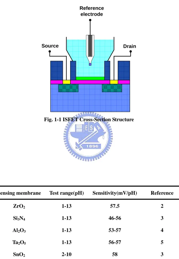
Table 1-1 Sensitivities and test range for different sensing membranes 30
Figure captions
Fig 1-1 ISFET Cross-Section Structure 30
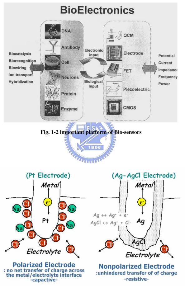
Fig 1-2 Important platform of Bio-sensors 31
Fig 1-3 Electrode structure 31
Fig 1-4 Conventional glass electrode 32
Fig 1-5 Using solid-state technology in measurement system 33
Fig 2-1 Structure of MOSFET and ISFET 33
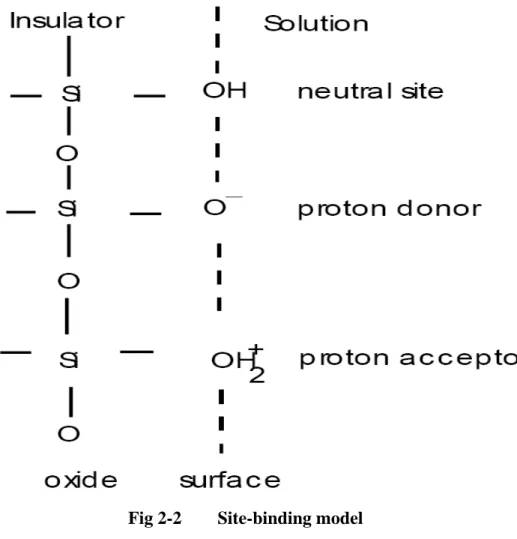
Fig 2-2 Site-binding model 34
Fig 2-3 Silicon dioxide and electrolyte interface 35
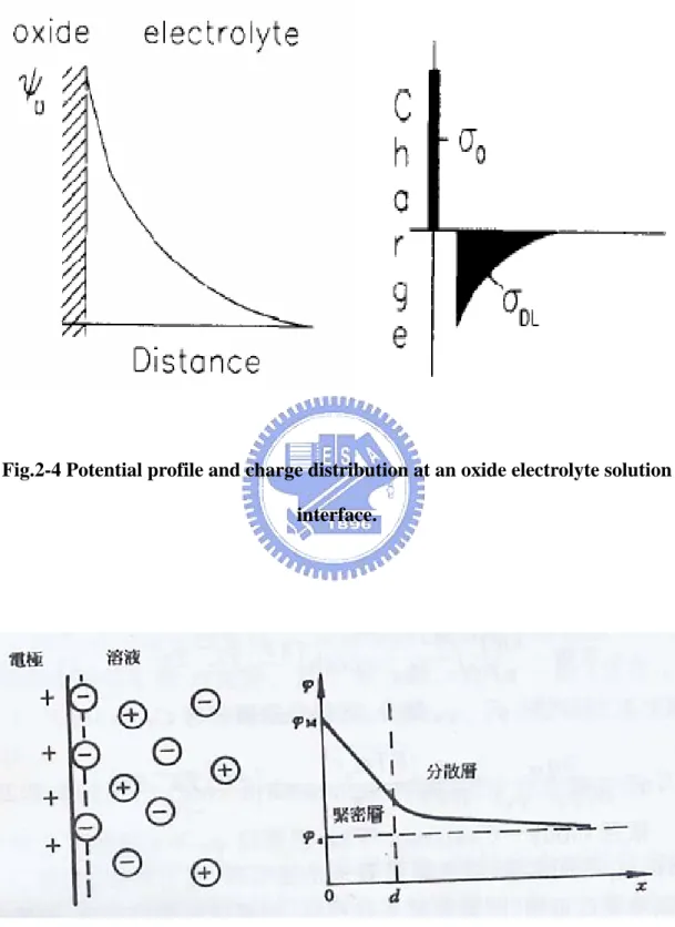
Fig 2-4 Potential profile and charge distribution at an oxide electrolyte solution interface
36
Fig 2-5 Gouy-Chapman-Stern model 36
Fig 2-6 Series combination of the (a)initial (b)hydrated insulator capacitance 37
Fig 3-1 Fabrication Process Flow 37
Fig 3-2 Measurement set-up 42
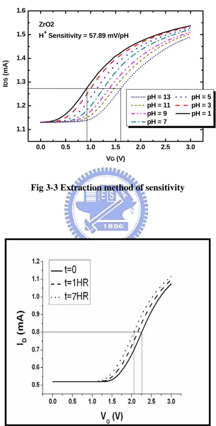
Fig 3-3 Extraction method of sensitivity 43
Fig 4-1 The comparison between enclosure and entrapment 44
Fig 4-2 The variety of ZrO2 sensitivity to H+after coated with PR/Nafion 44
Fig 4-3 The variety of ZrO2 H+ sensitivity after coated with PR :Nafion=1:1 45
Fig 4-4 The comparison of surface potential between ZrO2 and SiO2 45
Fig 4-5 Time to drift in pH buffer solution of ZrO2/PR/Nafion REFET for 4 hours
46
Fig 4-6 Time to drift in pH buffer solution of ZrO2-mix(PR1:Nafion1) REFET for 4 hours
46
Fig. 4-7 The drift phenomenon in different structure 47
Fig.4-8 Compare in different sensing-layer 47
Fig. 4-9 The variety of SiO2 H+ sensitivity after coated with PR and Nafion 48
Fig. 4-10 Time to drift in pH buffer solution of SiO2-mix(PR1:Nafion1) REFET for 4 hours
48
Fig. 4-11 The drift phenomenon in different sensing-layer 49
Fig. 4-12 The comparison between different proportions of PR and Nafion 49
Fig. 4-13 The variety of SiO2 H+ sensitivity after coating with PR:Nafion= 5:1 50
Fig. 4-14 Time to drift in pH buffer solution of ZrO2-mix(PR5:Nafion1) REFET for 4 hours
50
Fig. 4-15 The drift phenomenon in different proportions of PR:Nafion 51
Fig. 4-16 Sensitivity variety from 1st to 2nd measurement of ZrO2-mix(PR1:Nafion1)
Fig. 4-17 Sensitivity variety from 1st to 2nd measurement of ZrO2-mix(PR5:Nafion1)
52
Fig. 4-18 The variety of sensitivity in 8 hours 52
Fig. 4-19 Drift variety from 1st to 2nd measurement of ZrO2-mix(PR1:Nafion1) 53
Fig. 4-20 Drift variety from 1st to 2nd measurement of ZrO2-mix(PR5:Nafion1) 53
Fig. 4-21 Drift v.s. time in 4hours 54
Chapter 1
Introduction
1.1 What is ISFET?
The fervor of researching ISFET device started from P.Bergveld present Ion-sensitive-field-effect-transistor (ISFET) [1] which use SiO2 as gate in 1970, since device combine Metal-oxide-semiconductor-field-effect-transistor (MOSFET) with the concept of traditional Ion-sensitive-electrode. The main difference of structure is replacing the traditional MOSFET metal gate with SiO2 layer of insulation as sensing layer. The sensitivity and the pH value in buffer solution can be calculated by the current transformation caused by H+ ions difference on sensing layer when component dropped into different pH buffer solution.
Incipient research drawback is there is unstable reference voltage waiting for the solution of measure, so the researcher adds a stable reference electrode in succession to waiting for the solution of measure in the later research. Different application of material is found out because the property is not ideal when the device with Sio2 sensing layer. For instance, the property of (Table 2-1) ZrO2[2], Si3N4[3], Al2O3[4], Ta2O5[5] and SnO2[6] sensing layer are all better than SiO2 sensing layer. With the study of sensing layer, some material is found can detect different ions that are the structure based in ISFET, for example, K, Na, Ca ions in the human body, hence, ISFET open the way to BioElectronics further. The structure can apply on medicine, agriculture and chemistry widely.
For the mature of IC process techniques, ISFET has developed to another peak. There are some features:
(1)Small size (2)Rapid response (3)Strong robustness
(4) Compatible the CMOS process nowadays and lower the cost
But the stability and minimization of the component is another developing worry, if it replace the traditional glass electrodes with solid-state electrode made by noble metals, it would produce an unstable voltage though benefit the minimization. The significant challenge is finding a structure with stable voltage after the minimization, and it also open up a new page on ISFET field to Nano Technology.
1.2 Application of various kinds of electrodes in ISFET
In the research of ISFET, it can produce the electrodes which stabilize the electric potential to utilize one successively, to analyze pH value in the solution. The electrodes applied most are glass electrode and solid-state electrode. (Shown in Fig.1-3)
1.2.1 The glass electrode
The first glass electrode is developed by Cremer in 1906 and after that many efforts have been to take up with improves its application. The glass electrode is composed of a bulb of glass membrane, which only allows hydrogen ions to pass through a small channel, and a buffered chloride solution inside in contact or a fixed concentration of HCl with an internal reference electrode, which use of Ag/AgCl, as shown in Fig. 1-4.
transfer in interface of bulb surface and pH buffer solution. This reaction can for hydrogen ion in the solution exchanged stable and build up hydrogen ions on surface of ISFET [6]. For the purpose of good and stable sensing glass, the sensing glass often contained other component like Na2O-CaO-SiO2, Li2O-BaO-SiO2, Li2O-Cs2O-La2O3-SiO2, et al. [7]. For example, the introducing of alkali (ex. Li) oxide will break the stable Si-O bond and result the change between Li+ and H+:
+
( ) ( )
( ) (
SiO Li glass membrane H solution
SiO H hydrated layer Li solution
− + +
− +
+
⇒ + )
At reaction, the charges produced and regard as the carrier by Li, with the defect principle of the glass; jump from valance band to another, becoming electric potential competently, the relation between it activity of hydrogen ions is according to Nernst equation: 0 ln H RT E E nF α + = +
where E=electrode potential, Eo=standard potential of the electrode, R=gas constant (8.31441JK-1mol-1), T=temperature (in Kelvin scale), n=valance (n=1 for hydrogen ions), F=Faraday constant and αH+=activity of hydrogen ions.
According to equation, providing that at one side of the interface the activity of the ion of interest is kept constant, the electrode potential is a direct logarithmic function of the ion activity on the other side [7]. Then can easily define a stable potential, provided that no interference reaction will occur. The volume of glass electrode is too large. To apply ISFET more generally, it is necessary to miniaturize the glass electrode. The ISFET-based pH sensor is a new technique for pH detection and it has a big potential for widely application because of the advanced IC fabrication techniques nowadays.
1.2.2 The solid-state reference electrode
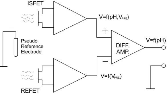
The solid-state reference electrode materials usually use noble metal as Ag, Pt, et al, but it relatively expensive. However the characteristic of the noble metal material is steady, it is difficult reaction in the solution. But it is unable to produce ion-exchange reactions like glass electrode. When turn on a potential in solid-state reference electrode, it causes the main factor of the unstable voltage because the metal surface forms the ion absorbs unstably. The characteristic is just like electric capacity. Some scholars utilize this characteristic; make another model of detection pH sensor [8]. (Shown in Fig1-5) The axiom is utilizing two ISFET; one of the ISFET is high sensitivity, the other is low sensitivity. In the same condition, ISFET use solid-state reference electrode to give a voltage. Solid-state reference electrode will produce an unstable voltage, but the value of pH buffer solution can be measured by circuit principle of op amplifier.
The unstable problem may come from the redox reaction or other reactions at noble metal reference electrode and the liquid interface, i.e. the liquid/solid interface. In ISFET, to integrate a stable potential at the interface is a way to the solid-state reference electrode.
1.3 Motivation of this work
There are two ways for ISFET to attain diminution, one is replacing ISFET's
glass electrode with solid state electrode, and another is REFET. Because solid state
electrode in electrolyte interface is thermodynamically undefined, it will produce an
unstable electrolyte. If modifying the solid-liquid interface is difficult, it use two devices,
sensitivity to an ISFET. There are two popular manufacturing way of REFET now, one is
in the original sensing layer with plasma treatment, another is deposition on top of sensing
film with polymer membrane. This study use polymer as sensitivity to compare with
DRIFT, and it make a better REFET.
1.4 References
[1] P. Bergvled,”Development of an ion-sensitive solid-state device for neurophysiological measurement”, IEEE Trans. On Bio-Med. Eng. (1970) 70-71
[2] K. M. Chang, K. Y. Chao, T. W. Chou, and C. T. Chang, “Characteristics of Zirconium Oxide Gate Ion-sensitive Field-Effect Transistors” Japanese Journal of Applied Physics Vol. 46 No.7A pp.4334-4338, 2007.
[3] H. K. Liao, J. C. Chou, W. Y. Chung, T. P., and S. K. Hsiung, ”Study on the interface trap density of the Si3N4/SiO2 gate ISFET” Proceeding of the Third East Asian Conference on chemical Sensor, Seoul, South Korea, pp.394-400, November 1997.
[4] S. Jamasb, S. Collins, and R. L. Smith, “A physically-based model for drit in Al2O3-gate pH ISFET’s”, Tech. Digest, 9th Int. Conf. Solid-State Sensors and Actuators (Transducers’97), Chicago, IL, 15-19, pp.1379-1382, June, 1997. [5] P. Gimmel, B. Gompf, D. Schmeiosser, H. D. Weimhofer, W. Gopel, and M. Klein,
“Ta2O5 gate of pH sensitive device comparative spectroscopic and electrical studies”, Sensors and Actuators B vol. 17 pp. 195-202, 1989.
[6] Y. Q. Miao, J. R. Chen and K. M. Fang, “New technology for the detection of pH”,
J. Biochem. Biophys. Methods, vol. 63, pp. 1-9, 2005.
[7] P. Bergveld, “ISFET, Theory and Practice”, in IEEE Sensor Conference, Toronto, Oct. 2003.
[8] P. Bergveld, “Thirty years of ISFETOLOGY What happened in the past 30 years and what happen in the next 30 years”, Sensors and Actuators B, vol. 88, pp. 1-20, 2003.
Chapter 2
Theory Description
2.1 The concept of pH
PH is a measure of the acidity or alkalinity of a solution. The letters "pH" stands for Potential of Hydrogen. Aqueous solutions at 25 ℃ with a pH less than seven are considered acidic, while those with a pH greater than seven are considered alkaline. The pH of 7.0 is defined as 'neutral' at 25 ℃ because at this pH the concentration of H O3 + equals the concentration of OH− in pure water[1]. The name, pH, can be derived from a combination of “p” the word power with “H” for the symbol of the element hydrogen [2]. The formula for calculating pH value is defined as:
10
log [ ]
pH = − α H+ (2-1)
where α is the activity coefficient and [H+] is the molar concentration of solvated protons in units of moles per liter. From equation (2-1) pH is used to specify the degree of acidity or basic of an aqueous solution at a given temperature. The term activity is used because pH reflects the amount of available hydrogen ions, not the concentration of hydrogen ions.
2.2 Theory of ISFET
P. Bergveld developed Ion-selective field effect transistors (ISFETs) first in1970s. The ISFET was developed by MOSFET (Metal Oxide Semiconductor Field Effect Transistor). The ISFET used to measure ion concentration in solution. Besides the gate electrode is replaced by reference electrode and inserted in buffer solution which contact with the sensing layer. The reference electrode provide for stable ion transfer, because the electrolyte potential will be unstable and is influenced by noise easily without it. The structure of MOSFET and ISFET are shown in Fig 2-1. [3]
2.2.1. Operation of ISFET
The ISFET structure is similar to MOSFET. The general expression for the drain current of MOSFET and thus also of the ISFET in non-saturated region is:
1
( 2 )
D gs T ds ds
I =β V −V − V ⋅V (2-2) in which β is a parameter determined by the mobility μ of the majority carrier in the inversion layer, is the oxide capacity per unit area and W and L is the width and length of the channel, according to:
ox C / ox C W L β μ= (2-3) The threshold voltage VT is given by:
2 M si ox ss B T F ox Q Q Q V q C φ Φ − Φ + + = − + (2-4) With Φ the workfunction of the gate metal, M Φ the silicon workfunction, Si
the fixed oxide charge and
ox Q ss
Q the surface state density at the silicon surface, QB is
the depletion charge in the silicon and φF the Fermi-potential.
From equation (2-4) it can be seen that the threshold voltage of a MOSFET is determined by material properties such as the workfunction and charge accumulation. For a stable operation of a MOSFET it is of importance that the threshold voltage is constant which can be achieved by applying an appropriate MOS process such as ion implantation. Equation (2-2) shows that the drain current is now only a function of the gate voltage, using a constant drain-source voltage [1].
Φ
In the case of ISFET has different item. The threshold voltage contains also terms which the interface between the liquid and oxide, the others between liquid and reference electrode. The term is the reference electrode potential relative to vacuumEref , which includes Φ . The interface potential at the gate oxide-electrolyte M
constant, and the surface potential Ψ , which results from a chemical reaction, usually 0 governed by the dissociation of oxide surface groups. The resulting equation for an ISFET
is thus given by:
0 Si ss ox 2 t ref sol ox Q Q V E q C f χ Φ + φ = − Ψ + − − + (2-5) The of this term which makes the ISFET sensitive to the electrolyte pH, which
is controlling the dissociation of the oxide surface groups. To design a pH sensitive ISFET
with a maximum sensitivity and selectivity need applies on a detailed investigation of the
oxide-electrolyte interface in order to be able to choose the best oxide, which is not a priori
silicon dioxide as used for MOSFETs.[4]
0
Ψ
2.2.2 Oxide/electrolyte interface
The site-binding model introduced by Yate et al [5]. The oxide/electrolyte interface will build up charge when the ISFET in pH solution, so site-binding model explains oxide-electrolyte interface basic theory of ISFET. In fig 2-2, fig 2-3, and fig2-4 are indicated that reaction can between protons in the solution and hydroxyl groups formed at the SiO2-solution interface. [1][4][6] The mechanism can describe interface for the combination and generation of hydroxyl. To describe the equilibrium the so-called amphoteric SiOH surface sites and H+-ions in the solution. The surface reaction: a K S SiOH←⎯⎯⎯⎯→SiO−+H+ (2-6) 2 b K S SiOH+←⎯⎯⎯⎯→SiOH+H+ (2-7) where the HS
+ represents the protons at the surface of oxide, and are
the chemical equilibrium constants.
a
the equilibrium constants Ka and Kb are given by:
[
]
s SiO HS a SiOH v a SiO H K or SiOH v − + − + ⎡ ⎤ ⎡ ⎤ ⋅ ⎣ ⎦ ⎣ ⎦ = (2-8)[
]
2 2 SiOH HS b SiOH s v a SiOH K or v SiOH H + + + + ⋅ ⎡ ⎤ ⎣ ⎦ = ⎡ ⎤ ⎣ ⎦ (2-9) where S means the surface.The potential between insulator oxide and electrolyte solution causes a proton concentration difference between the bulk and surface (Fig. 2-4) that based on Boltzmann. [7]
with Boltzmann equation :
0 0 exp ( )= S B S B H H q q a a or pH pH kT kT ψ ψ + + − = − (2-10) where the S H a + and B H a + are activities of HS
+ at oxide surface and solution bulk,
is the Boltzmann constant, is the absolute temperature, is the pH value at the oxide surface,
k
T pHs
B
pH is the pH value in the solution bulk,ψ0 is surface potential..
then we can get the fixed number of surface sites per unit area, NS
2
S SiOH SiO SiOH
N =v +v − +v + (2-11)
where v is
to depend on some electrochemical knowledge and math derivation, a surface charge density 2 exist: 0[ /C m ] σ (2-12)
(
2)
0 q vSiOH vSiO qB σ = + + − = −where B is the number of negatively charged groups minus the number of
positively charged groups in mole per unit area. There will be no net charge on the surface when the number of positively and negatively charged groups on the surface is equal and consequently. We say the pH value at the point of zero charge is pHpzc in
this case. One more thing we have to know is that different operations of ISFETs (flat band condition and linear region) will yield different value of pHpzc [8].
0 σ is given by: 2 2 S S S a b H o a b b H H a K K qNs K K K a a σ + + + ⎛ − ⎞ ⎜ = ⎜ + + ⎝ ⎠ ⎟ ⎟ (2-13) A detailed derivation can see the Ref [1] [4]. When we obtain the surface charge
density, we can find the intrinsic buffer capacity; to take the pH variation on surface can be defined: o int S S B q pH pH q σ β ∂ = − ∂ = − ∂ ∂ (2-14) int
β is known as intrinsic buffer capacity, to depend on the activity of surface
-ions. Finally we can obtain the equation for the intrinsic buffer capacity:
H+
(
)
2 2 int 2 4 2.3 S S S S S b H a b H a b S H a b b H H K a K K a K K N a K K K a a β + + + + + + + = + + (2-15)It is only capable of buffering small changes in surface pH (pH ), and not in bulk S
pH(pH ), so it is called intrinsic in this case. The values of Nb S, Ka and Kb are oxide
dependent. It can been seen that the number of surface sites influences the intrinsic buffer capacity. Hydrolysis of the surface will create more surface sites and thus a rise in the intrinsic buffer capacity and sensitivity. [4]
Both surface reaction and electrolyte will influence the surface charge density. In order to charge neutrality, the surface charge σ0 was balanced off an equal but opposite charge in electrolyte. The two opposite charges, σ0 and σdl, parallel to each other from the electrical double layer structure. The position of this charge density σdl defines the double-layer and the two opposite charge, σ0 and σdl, parallel to each other from the integral double-layer capacitanceCdl i, .
0 ,
dl Cdl i 0
σ = −σ = − ×ψ (2-16) where the potential of the oxide surface and the bulk solution, ψ0 =ψS −ψB.[4]
Gouy-Chapman-Stern model can calculate the integral double-layer capacitance . (Fig.2-5) [9] The double-layer capacitance consists of a series network of a Helmholtz-layer capacitance (the Stern capacitance) and a diffuse-layer capacitance. The Gouy-Chapman-Stern model involves a diffuse layer of charge in the solution starting at a distance x
, dl i
C
E from the surface. The charge in the diffuse layer σdl is given
by: 0 0 8 sinh 2 E dl r zq kT n kT φ σ = − ε ε ⎛⎜ ⎝ ⎠ ⎞ ⎟ (2-17)
where φE is the potential at xE, n
0 is the concentration of each ion in the bulk solution in number, and z is the valence of the ions. The parameters εr, ε0, k, q and T have their usual meaning.
The difference between the potential ψ1 at YT and the surface potential ψ0 is the potential difference across the Stren capacitance. Therefore the potential ψ1 can be described by: 0 1 0 0 0 E Stren r 0x C σ σ ψ ψ ψ ε ε = − = − (2-18) now it is possible to calculate the integral double-layer capacitance as a function of
0
ψ and the electrolyte concentration with eqns.2-15 and eqns.2-16. The ability of the double layer to store charge in response to a small charge in the potential 0
0
σ ψ
∂ ∂ is defined as the differential double-layer capacitance, Cdif, and can be calculated:
0 0 0 dl dif C σ σ ψ ψ ∂ = −∂ = ∂ ∂ (2-19)
For reasons of simplicity, not the expression for Cdif is started here, but of its inverse, which also clearly shows that this capacitance is made up of two components in series:
0 2 2 0 0 0 1 1 1 1 2 cosh( ) 2 dif Stren r C C z q n zq kT kT ψ σ ε ε ψ ∂ = = + ∂ (2-20)
To combine eqns.2-12 and eqns.2-17 shows the effect of a small change in the surface pH(pHs) on the change in the surface potential ψ0:
0 0 0 0 S S q pH pH C int dif ψ ψ σ β σ ∂ ∂ ∂ − = ⋅ = ∂ ∂ ∂ (2-21) cause the general expression for pH sensitivity of an ISFET:
0 2.3 B kT pH q ψ α ∂ = − ∂ ⋅ (2-22) when 2 int 1 2.3 1 diff kTC q α β = + (2-23)
Depending on the intrinsic buffer capacitance Cdif, the parameter α is a dimensionless sensitivity parameter that varies between 0 and 1. If α=1, the ISFET has a so-called Nernstian sensitivity of precisely-59.2mV/pH at 298K, which is also the maximum achievable sensitivity.
To use SiO2 from the MOSFET process does not obtain the requirements of a high value of βint. The pH sensitivity is only about 30mV/pH., so the research nowadays is to find high sensitivity sensing film. The material found by high sensitivity is Si3N4[9],[10] Al2O3[11],[12] and SnO2.[13]
2.3 Drift
This phenomenon can be considered by two aspects, the trap of hydrogen-bearing species, and the hydration of the insulator surface after immersed in pH solution by the binding sites when they transport through the insulator. That is influence on drift is generally smaller than the latter. This result can be found in the measurement data of the research. This phenomenon is slow, continuous, change of
threshold voltage of an ISFET and it is difficult to identify the cause of this phenomenon, which could be either a surface or a bulk effect, or both. There are a number of possible reasons causes of drift. [14]
(1) Injection of electrons from the electrolyte at strong anodic polarizations created negative space charge inside sensitive film.
(2) Some surface effects, such as the rehydration of a surface that is partially dehydrated and ion exchange involving OH− ions.
(3) Variation of the surface state density (Dit) at the Si SiO interface which 2
means the drift dependence of diffusion mechanism.
(4) Drift of sodium ion under the influence of the insulator field. Given an effective diffusion coefficient , it is clear that a bulk redistribution of sodium which has left a trap near the edge of the .
eff D 2 SiO 2.3.1 Dispersive Transport
Dispersive transport was brief reviewed in[15] and should be characterized by a power-law time delay of mobility or diffusivity of the from 1,
tβ − 0< <β 1. In
amorphous material, dispersive transport may arise from hopping transport, multiple-trap transport, or trap-controlled hopping transport.[16] Regardless of the specific dispersive mechanism involved, dispersive transport leads to a characteristic power-law time decay of diffusivity which can described by:
1 00 0
( ) ( )
D t =D ωt β− (2-24)
where is a temperature-dependent diffusion coefficient which obeys an Arrhenius relationship,
00 D
0
ω is the hopping attempt frequency, and β is the dispersion parameter satisfying 0< <β 1. Dispersive transport leads to decay in density of
sites/traps occupied by the species undergoing transport. This decay is described by the stretched-exponential time dependence given by:
/ ( ) / (0) exp[( / )]
S T S T
N t N t τ
Δ = Δ − (2-25) where ΔNS T/ ( )t is the area density (unit of cm-2) of sites/traps occupied, τ is the time constant combined with structural relaxation, and β is the dispersion parameter.
2.3.2 Expression for Drift
The hydration lead to the chemical composition of the sensing layer, it is reasonable to assume that the dielectric constant of the hydrated surface layer differs from that of the sensing oxide bulk. The overall insulator capacitance, which is determined by the series combination of the surface hydration layer and the underlying sensing film, will exhibit a slow, temporal change. When drift phenomenon occurs at the surface of an activity-biased ISFET, the gate voltage will simultaneously exhibit a change to keep a constant drain current. The change of the gate voltage can be written as
( ) ( ) (0)
G G G
V t V t V
Δ = − (2-26) Since the voltage drop inside of the semiconductor is kept a constant,
becomes: ( ) G V t Δ (2-27) ( ) [ ( ) (0)] [ ( ) (0)] G FB FB ins ins V t V t V V t V Δ = − + −
where is the flatband voltage and is the voltage drop across the insulator. and are given by the following expression:
FB V Vins FB V Vins 0 sol Si OX SS FB ref OX Q Q V E q C χ Φ + = + − Ψ − − (2-28) ( B inv ins OX Q Q V C ) − + = (2-29)
where the is the inversion charge. If the pH, temperature, and the ionic strength of the solution are held constant,
inv Q
ref
E , Φ , Si Ψ , and0 χsol can be
neglected, so the drift an be rewritten as:
1 1 ( ) ( )[ ] ( ) (0) G OX SS B inv i I V t Q Q Q Q C t C Δ = − + + + − (2-30) In this study, the gate oxide of the fabricated ISFET was composed of two layers, a lower layer of thermally-grown of thickness, , and an upper layer of sputter-grown
2
SiO tL
2
ZrO of thickness, . is the effective insulator
capacitance given by the series combination of the thermally-grown capacitance, U t CI(0) 2 SiO L tL
ε , and the sputter-grown ZrO capacitance, 2 εU tU . is
analogous to , but an additional hydrated of capacitance make always smaller than , ( ) i C t (0) I C Ci I
C εHL tHL, at the oxide-electrolyte interface must be considered,
and the sputter-grown ZrO capacitance is now given by 2 εU [tU −t ]HL . The series
combinations of the capacitance are illustrated in Fig.2-6. Therefore, the drift is given by: ( ) U HL G OX SS B inv HL U HL V Q Q Q Q ε ε t ε ε ⎡ − ⎤ Δ = − + + + ⎢ ⎥ ⎣ ⎦ ( )t (2-31) From the equation, we known that drift of gate voltage Δ if the substrate type VG
was different, it is depend on the and . Other terms at eqns.2-29 can be appropriate as constant value no matter what the substrate is. According to this assume it is possible to eliminate the drift or hold the drift to be a constant at any other pH aqueous solution through the CMOS ISFET. By applying dispersive transport theory, an expression for is given by[15]
inv Q QB ( ) HL t t
{
}
( ) ( ) exp ( / ) HL HL t t =t ∞ − ⎡⎣− t τ β⎤⎦ (2-32) with1 00 0 / (0) ( ) S T HL D hydr D N t A N β ω β −Δ ∞ = (2-33)
where A is the cross-sectional area, and D is the average density of the
hydrating species per unit volume of hydration layer. Hence, combination of eqns.2-24 to eqns.2-30 the gate voltage drift can be expressed by the following equation: hydr N
{
}
( ) ( ) U HL ( ) 1 exp ( / ) G OX SS B inv HL U HL V t Q Q Q Q ε ε t t τ β ε ε ⎡ − ⎤ ⎡ ⎤ Δ = − + + + ⎢ ⎥ ∞ − ⎣− ⎦ ⎣ ⎦ (2-34)From this equation, we can expect that if the time of gate oxide immersing in the test-solution is long enough, the gate voltage drift will approach a constant value which is greatly dependent on the hydration depth, tHL( )∞ .
2.4 References
[1] P. Bergveld, “ISFET, Theory and Practice”, in IEEE Sensor Conference, Toronto, Oct. 2003.
[2] Y. Q. Miao, J. R. Chen and K. M. Fang, “New technology for the detection of pH”,
J. Biochem. Biophys. Methods, vol. 63, pp. 1-9, 2005.
[3] P. Bergveld, “Thirty years of ISFETOLOGY What happened in the past 30 years and what happen in the next 30 years”, Sensors and Actuators B, vol. 88, pp. 1-20, 2003.
[4] R.E.G. van Hal et al. , “A general model to describe the electrostatic potential at electrolyte oxide interface”, Advance in Colloid and Interface Science, vol.69, pp.31-62, 1996.
layer at oxide/water interface. J. chem. Soc. Faraday Trans. I, 70 (1974) pp.1807-1818.
[6] Miao Yuqing , Guan Jianguo, Chen Jianrong, “Ion sensitive field transducer-based biosensors”, Biotechnology Advances, vol. 21, pp.527-534, 2003.
[7] W. M. Siu and R. S. C. Cobbold. ”Basic Properties of the Electrolyte-SiO2-Si System: Physical and Theoretical Aspects, ”IEEE Trans. Electron Device, ED vol. 26, pp. 1805-1815, 1979.
[8] H.K. Liao, et al. ”Study on pHpzc and surface potential of tin oxide gate ISFET”,
Materials Chemistry and Physics, vol. 59, pp.6-11, 1999
[9] 吳浩青, 李永舫, "電化學動力學", 科技圖書公司, 2001 年 2 月
[10] Tadayuki Matsuo, Masayoshi Esashi, ”Methods of ISFET Fabrication”, Sensors
and Actuators, vol. 1, pp.77-96, 1981.
[11] Imants R. Lauks, Jay N. Zemel, “The Si3N4/Si Ion-Sensitive Semiconductor Electrode ”, IEEE Transactions on Electron Devices, vol. ED-26, no.12, pp. 1959- 1964, Dec., 1979.
[12] J.C. Chou, C.Y. Weng, “Sensitivity and hysteresis effect in AL2O3 gate pH- ISFET ”, Materials Chemistry and Physics, vol. 71, pp.120-124, 2001.
[13] H.K.Liao et al.,” Study of amorphous tin oxide thin films for ISFET applications”, Sensors and Actuators B, vol.50, pp.104-109, 1998.
[14] Luc Bousse and P. Bergveld, The role of buried OH sites in the response mechanism of inorganic-gate pH-sensitive ISFETs, Sens. Actuators 6 (1984) 67-78.
[15] S. Jamasb, S. D. Collins, R. L. Smith, ”A Physical Model for Threshold Voltage Instability in Si3N4-Gate H+-Sensitive FET’S ( pH ISFET’s )”, IEEE Transactions
[16] G. Pfister, H. Scher, ” Time-dependent electrical transport in amorphous solid: As2Se3”, Physical Review B, vol. 15, no. 4, pp.2062-2082, Feb., 1977.
Chapter 3
Experiment and Measurement
3.1 Introduction
The ISFET is similar to conventional MOSFET. The difference between MOSFET and ISFET structure is the process of gate electrode. This chapter introduce to process flow and structure of ISFET. (Fig.3-1)
Setp1:
1. RCA clean.
2. Wet oxide growth 6000Ǻ, 1050°C, and 65mins. Step2:
3. Mask#1 to define Source/Drain region. 4. BOE wet etching of silicon dioxide.
5. Dry (Screening) oxide growth 300 Ǻ, 1050°C, 12mins.
6. Source/Drain implantation, Dose=5E15 (1/cm2), Energy=25Kev. 7. Source/Drain annealing, 950°C, 30mins.
Step3:
8. PECVD Oxide deposition 1μ m. Step4:
9. Mask#2 to define contact hole and gate region. 10. BOE wet etching of silicon dioxide.
11. Dry oxide growth 100 Ǻ, 850°C, 60mins. Step5:
13. Sensing layer (ZrO2) deposition by Sputtering.300 Ǻ. 14. ZrO2 sintering 600°C, 30mins.
Step6:
15. Mak#4 to define the contact and solid reference electrode region. 16. Al deposition by Sputtering 5000 Ǻ.
Step7:
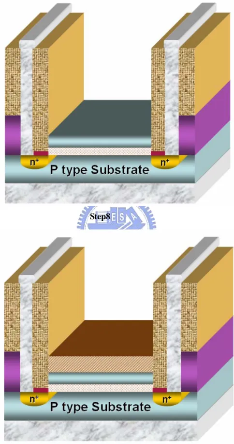
17. Backside Al evaporation 5000 Ǻ. 18. Pt and Al sintering 400°C, 30mins Step8:
19. Coating the polymer-based material as REFET sensing layer.
3.2 The step illustration
In step1, RCA clean is for cleaning up the surface, to make the growing equality of Wet Oxide better.
In step2, the area defined source-drain grow a layer of 100A screen oxide to protect the surface when ion-implantation. After ion-implantation, high potential doping ion destroy the structure of lattice on silicon, and repair it by the way of anneal.
In step3, then using PECVD grow oxide 1μ as insulation to prevent buffer m
solution effect the device when ISFET immersed in the solution.
In step4, decide the gate oxide region, and then use BOE etching oxide. It grows better quality gate oxide100A by using dry oxide.
In step5, define the sensing layer region for growing 300A ZrO2 cause the sensitivity of metal oxide higher, which is about 57mv/pH.
In step6, define electrode region for deposition 5000A Al.
ISFET.
In step8, ISFET coated polymer is REFET sensing layer since polymer lower sensitivity efficiently.
3.3 Measurement system
To investigate the characteristics of polymer structure as sensing layer, we used the HP4156 as measurement tool and system (shown in Fig.3-2) to measure I-V curve for pH-ISFETs. In order to get correct result of measurement, the entire measurement procedures were executed in a dark box to prevent the electromagnetic wave and light influence.[1] The measured pH values are 1,3,5,7,9,11,13, and the pH buffer solution were supplied by Riedel-deHaen corp.
In order to measure Na+ ions, so must to prepare the NaCl solution. The NaCl salts are electronic grade and solution are prepared in DI water with different concentration. When preparation of NaCl solution, it have to know the solubility of NaCl at room temperature is about 37g NaCl per 100g water.
3.3.1 Current-Voltage (I-V) measurement set-up
A HP-4156 semiconductor parameter analyzer system were setup to measure the I-V characteristic curves, in which include IDS-VGS and IDS-VDS curve at controlled temperature. When dropping the buffer solution, must be careful. Because the sensing region is too small, it could easily generated air bubbles at interface. In order to measure exact values for difference solution, every pH solution is immersed for the same time before measurement.
region. Next, we define the IDS as constant to measure IDS-VGS. In this operate condition, it can find the characteristics of pH-ISFET. It can find the pH sensitivity from IDS-VGS curve of maximum transconductance. Beside, we can see that with different buffer solution the reference electrode voltage is shifted and shifted voltage per pH value is sensitivity, shown in Fig.3-3.
3.3.2 Current-Voltage (I-V) measurement set-up with drift
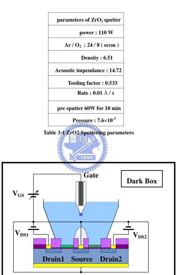
In order to measure drift phenomenon of pH-ISFETs with the same buffer solution and the same condition samples period of seconds, minutes and hours. After seven hours, we can compare drift phenomenon of all samples. This detection principle is in a similar manner to that of the pH measurement and is shown in Fig.3-4.
3.4 References
[1] Paik-Kyun Shin,”The pH-sensing and light-induced drift properties of titanium dioxide thin films deposited by MOCVD”, Applied Surface Science, vol. 214, pp.214-221, 2000.
Chapter 4
Results and Discussions
4.1 Introduction
This experiment use a high polymer, it is a hydrophobic material which can reduce H ion in a large number, the shortage is vulnerable to buffer solution in the sensing film, so we utilize a way that Nafion entrapment PR to produce REFET(Reference Electrode Field Effect Transistor). Since Nafion is a proton exchange membrane, it can protect PR for this feature and it become the mechanism of proton exchange to make ion absorb on the surface of PR steadily in fear of peel for the attack of buffer solution in a short time. This experiment discusses a best REFET (Reference Electrode Field Effect Transistor) in different structure and in various viewpoints.
4.2 Comparison of different structure’s feature
The experiment utilizes different approach of entrapment to measure the comparison of its structure’s feature. It use ZrO2/PR/Nafion and ZrO2-mix(PR+Nafion) two different structure’s approach of entrapment, and get the common conclusion that sensitivity of both reduce from 56mV/p in ZrO2 sensing layer to 5mV/pH and 8.3mV/pH(Fig 4-2)(Fig4-3).
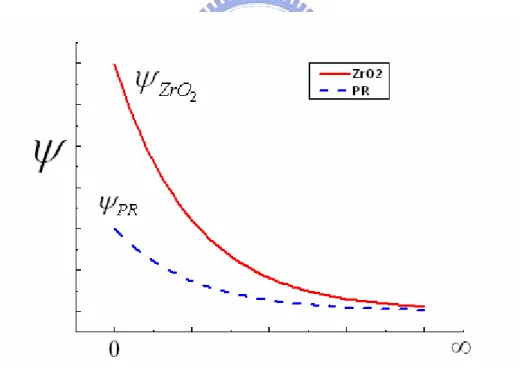
The main reason is the entrapment PR (FH6400) can reduce the sensitivity efficiently, and it can get different material’s site-binding from Gouy-Chapman-Stern
Theory model[2] and Site-binding model[3], which traps the number of ion are also different. In addition, ZrO2[4] is the material of high K and the sensitivity of metal oxide to H ion is higher, and PR is a PVC high polymer material that is not easy to absorb H ion, so it higher than ψPR in
2
ZrO
ψ , the sensitivity can reduce largely about 85%.
However, the performance of two structure on Drift since structure of ZrO2/PR/Nafion inferior to the structure of PR mix Nafion (Fig.4-5) (Fig.4-6)(Fig.4-7), buffer solution trough Nafion make the surface area that ions absorb to PR larger than the surface area of mingle one from the analysis of triple structure, and if uncovered PR immerse in buffer solution directly, it will easy to peel by the attack of solution quickly. Hence, the main reason that tripe layer structure is not stable as the mix one is the surface area of PR molecule contact with buffer solution larger than the surface area of mix one, so it is easy to attack by buffer solution.
4-3 The comparison of PR-mix-Nafion deposition on different
structure
The comparison of this experiment utilize two different base on different Sensing film, ZrO2 and SiO2(Fig.4-8), and the material of both of them mix PR and Nafion coast on sensing film to get the sensitivity are 8.3mV/pH and 13.3mV/pH respectively. The sensitivity measured in previously ZrO2 and SiO2 experiment are about 55mV/pH and 32.5mV/pH(Fig.4-3)(Fig.4-9). It concludes from site-binding model[1] and experiment data that the main reason affect sensitivity is ” hydrophobic” from PR material cause H+ ions uneasy to absorb, so the H ion mainly absorb on the surface of PR and it not connect with the sensing layer in bottom. Nevertheless, the structure
base on SiO2 is inferior to ZrO2 on the improvement of sensitivity and stability of drift (Fig.4-10),it perhaps because interface of SiO2 and PR is not as well as the interface of ZrO2 and PR.
4-4 The comparison of different PR-mix-Nafion proportion’s feature
This experiment utilize PR mix Nafion in different proportion, there are concentration 5:1 and 1:1 on sensing-layer entrapment ZrO2. Among the result that 0.01ml PR mix 0.01ml Nafion entrapment ZrO2, it can observe the sensitivity from the 54.16mV/pH in the begging reduce to 8.3mV/pH(Fig.4-3), the other is the result that 0.05ml PR mix 0.01ml Nafion entrapment ZrO2 reduce from 54.16mV/pHr to 4.16mV/pH(Fig.4-13). From this phenomena, it can detect the concentration of PR affect directly to the sensitivity of REFET and it further prove PR is the main reason of reducing sensitivity in 4-3.
The performance of Drift (Fig.4-6)(Fig.4-14) can get the two sample’s stability (PR1:Nafion1) is superior to (PR5:Nafion1) in the four hours later, the possible cause from the proportion of Nafion of the former higher than the later one. It mean the PR area entrap Nafion larger than the later, so it is uneasy to attack by the solution and cause PR peeling. In conclude, the sensitivity in (PR5:Nafion1) (Fig.4-15) is small and the time for stable of reliability is short, an the other vice versa.
4-5 The comparison of different proportion’s durability and
repeatability
This experiment utilizes two structures in 4-4 (Fig.4-12) continue to do long time durability test, the first stage is measure sensitivity by doing four hours DRIFT
experiment to the measured sample respectively, and the second stage repeat the first stage experiment again. In this research, it observed the experiment of the structure can’t bear doing long term measure immersed the solution, and the feature of sensitivity and drift measured in the four hours can be made as a REFET(Reference Electrode Field Effect Transistor). Also, it observed that the feature of the two kind of mix proportion on sensitivity and drift in the measure of second stage already peel almost wholly for the long time attack in the buffer solution to make the mixing layer of PR and Nafion of the sample be invalid. It is realized in this experiment the only fine REFET (Reference Electrode Field Effect Transistor) of the structure in the four hours short time is unappreciable to do the long time measure.
4.6 Conclusion
To integrate the above experiment result, the mix layer of Nafion and PR is a good (Reference Electrode Field Effect Transistor), it could reduce H+ Sensitivity from 57.5mV/pH to 8mV/pH. It use easy approach of entrapment to make Nafion do for the entrapped PR steadily through the mechanism of proton exchange, and it observed in the experiment the OXIDE and ZrO2 of the bottom of PR is not associated directly with the SENSITIVITY, the main effect reason is PR which is not easy for the absorbing of H ion.
4.7 References
[1] John Payne ”Nafion® - Perfluorosulfonate Ionomer”, April, 2005 from http://www.psrc.usm.edu/mauritz/nafion.html
electrolyte oxide interface”, Advance in Colloid and Interface Science, vol.69, pp.31-62, 1996
[3] 吳浩青, 李永舫, ”電化學動力學”, 科技圖書公司, 2001 年 2 月
[4] K. M. Chang, K. Y. Chao, T. W. Chou, and C. T. Chang, ”Characteristics of Zirconium Oxide Gate Ion-sensitive Field-Effect Transistors” Japanese Journal of
Chapter 5
Future work
From this experiment, it can realize that use the deposition feature of Nafion to entrap material of PR on a good sensing film and it get the feature of PR from the teat result. It can utilize the approach of entrapment to combine other substance (like protein, enzyme…etc) in the future, and ISFET develop BIO-SENSOR in further.
Source Drain Reference
electrode
Fig. 1-1 ISFET Cross-Section Structure
Sensing membrane Test range(pH) Sensitivity(mV/pH) Reference
ZrO2 1-13 57.5 2
Si3N4 1-13 46-56 3
Al2O3 1-13 53-57 4
Ta2O5 1-13 56-57 5
SnO2 2-10 58 3
Fig. 1-2 important platform of Bio-sensors
Fig. 1-5 using solid-state technology in measurement system Source Drain Reference electrode Gate Source Drain MOSET ISFET Fig 2-1 Structure of MOSFET and ISFET
Fig.2-4 Potential profile and charge distribution at an oxide electrolyte solution interface.
silicon silicon
Thermal Oxide Thermal Oxide
Sensing Layer
Sensing Layer Hydration
Solution Solution
Fig.2-6 Series combination of the (a) initial (b) hydrated insulator capacitance
Step2
Step4
Step6
Step8
Setp9
parameters of ZrO2 sputter power : 110 W Ar / O2 : 24 / 8 ( sccm ) Density : 6.51 Acoustic impendance : 14.72 Tooling factor : 0.533 Rate : 0.01 Å / s
pre sputter 60W for 10 min Pressure : 7.6×10⁻³
Table 3-1 ZrO2 Sputtering parameters
Dark Box
Drain2
Drain1 Source
V
DS2V
DS1V
GSGate
0.0 0.5 1.0 1.5 2.0 2.5 3.0 1.1 1.2 1.3 1.4 1.5 1.6 ZrO2 H+ Sensitivity = 57.89 mV/pH I DS (m A) VG (V) pH = 13 pH = 5 pH = 11 pH = 3 pH = 9 pH = 1 pH = 7 Fig 3-3 Extraction method of sensitivity
7
Fig.4-1 The comparison between enclosure and entrapment
-0.5 0.0 0.5 1.0 1.5 2.0 2.5 3.0 3.5 4.0 0.00230 0.00235 0.00240 0.00245 0.00250 0.00255 0.00260 0.00265 ID (A ) V G (V) pH 1 pH 3 pH 5 pH 7 pH 9 pH11 pH13 ZrO 2 H+ Sensitivity=56.67mV/pH -0.5 0.0 0.5 1.0 1.5 2.0 2.5 3.0 3.5 4.0 0.00225 0.00230 0.00235 0.00240 0.00245 0.00250 0.00255 0.00260 ID (A ) V G (V) pH 1 pH 3 pH 5 pH 7 pH 9 pH11 pH13 ZrO 2/PR/Nafion H+ Sensitivity=5mV/pH
-0.5 0.0 0.5 1.0 1.5 2.0 2.5 3.0 3.5 4.0 0.00135 0.00140 0.00145 0.00150 0.00155 0.00160 0.00165 0.00170 0.00175 0.00180 ID (A) VG (V) pH 1 pH 3 pH 5 pH 7 pH 9 pH11 pH13 ZrO2 H+ Sensitivity=54.16mV/pH -0.5 0.0 0.5 1.0 1.5 2.0 2.5 3.0 3.5 4.0 0.00130 0.00135 0.00140 0.00145 0.00150 0.00155 0.00160 0.00165 0.00170 0.00175 0.00180 Y A x is T it le X Axis Title pH 1 pH 3 pH 5 pH 7 pH 9 pH11 pH13 ZrO2-mix(PR1:Nafion1) H+ sensitivity=8.3mV/pH
Fig. 4-3 The variety of ZrO2 H+ sensitivity after coated with PR :Nafion=1:1
-2000 0 2000 4000 6000 8000 10000 12000 14000 16000 2.4 2.5 2.6 2.7 2.8 2.9 VG (V) Time (s) ZrO2/PR/Nafion
Drift in pHbuffer solution for first hour to fourth hour
0.346V
Fig4-5 Time to drift in pH buffer solution of ZrO2/PR/Nafion-REFET for 4 hours -2000 0 2000 4000 6000 8000 10000 12000 14000 16000 1.50 1.55 1.60 1.65 1.70 1.75 1.80 1.85 1.90 1.95 2.00 VG (V ) Time(s) 14.69mV Drift in pH buffersolution for first hour to fourth hour
ZrO2-mix(PR1:Nafion1)
Fig4-6 Time to drift in pH buffer solution of ZrO2-mix(PR1:Nafion1)-REFET for 4 hours
1.0 1.5 2.0 2.5 3.0 3.5 4.0 0 50 100 150 200 250 300 350 VG (mV ) Time (hour) ZrO2/PR/Nafion ZrO2-mix(PR1:Nafion)
Fig4-7 The drift phenomenon in different structure
Fig. 4-9 The variety of SiO2 H+ sensitivity after coated with PR and Nafion
-2000 0 2000 4000 6000 8000 10000 12000 14000 16000 1.6 1.8 2.0 2.2 2.4 2.6 2.8 3.0 3.2 3.4 3.6 VG (V) Time (s) Drift in pH buffer solution for first hour to fourth hour
0.529V
Fig4-10 Time to drift in pH buffer solution of SiO2-mix(PR1:Nafion1)-REFET for 4 hours
1.0 1.5 2.0 2.5 3.0 3.5 4.0 0 100 200 300 400 500 600 VG (V) Time (hour) ZrO2-mix(PR+Nafion) SiO2-mix(PR+Nafion)
Fig4-11 The drift phenomenon in different sensing-layer
Fig4-13 The variety of SiO2 H+ sensitivity after coating with PR:Nafion=5:1 -2000 0 2000 4000 6000 8000 10000 12000 14000 16000 1.600 1.625 1.650 1.675 1.700 1.725 1.750 VG (V ) Time (s) 20.20mV Drift in pH solution for first hour to fourth hour
ZrO2-mix(PR5:Nafion1)
Fig4-14 Time to drift in pH buffer solution of ZrO2-mix(PR5:Nafion1)-REFET for 4 hours
1.0 1.5 2.0 2.5 3.0 3.5 4.0 0 2 4 6 8 10 12 14 16 18 20 22 VG (V) Time (hour) ZrO2-mix(PR1:Nafion1) ZrO2-mix(PR5:Nafion1)
Fig4-15 The drift phenomenon in different proportions of PR:Nafion
Fig4-16 Sensitivity variety from 1st to 2nd measurement of ZrO2-mix(PR1:Nafion1)
Fig4-17 Sensitivity variety from 1st to 2nd measurement of ZrO2-mix(PR5:Nafion1) 0 2 4 6 8 0 10 20 30 40 50 60 Se n s itivity(m V /pH ) Time(hour) ZrO2-mix(PR1:Nafion1) ZrO2-mix(PR5:Nafion1)
Fig4-19 Drift variety from 1st to 2nd measurement of ZrO2-mix(PR1:Nafion1)
0 1 2 3 4 -2 0 2 4 6 8 10 12 14 16 18 20 22 VG (mV) Time(Hour) ZrO2-mia(PR1:Nafion1) ZrO2-mia(PR5:Nafion1)
Fig.4-21 Drift v.s. time in 4hours
4 5 6 7 8 0 10 20 30 40 50 60 VG (mV) Time (hour) ZrO2-mix(PR1:Nafion1) ZrO2-mix(PR5:Nafion1)
簡歷 姓 名:陳 明 聰 性 別:男 出生日期:民國 69 年 2 月 29 日 出 生 地:台灣省台北縣 住 址:台北縣鶯歌鎮中正一路 475 號 學 歷:私立龍華科大學電機工程學系 (民國 88 年 9 月~民國 92 年 6 月) 國立交通大學微電子奈米科技產業研發碩士專班 (民國 95 年 2 月~民國 97 年 2 月) 碩士論文:以NafionTM /PR包埋結構作為參考場效電晶體之感測層研究