以邊緣偵測為基礎的高效率強健式視訊物件分割技術
80
0
0
全文
(2) 以邊緣偵測為基礎的高效率強健式視訊物件 分割技術 An Efficient and Robust Edge-based Video Object Segmentation Method. 研 究. 生:李德淵. Student: Der-Uan Lee. 指導教授:林進燈博士. Advisor: Dr. Chin-Teng Lin. 國 立 交 通 大 學 電機與控制工程學系 碩士論文. A Thesis Submitted to Department of Electrical and Control Engineering College of Electrical Engineering and Computer Science National Chiao-Tung University In Partial Fulfillment of the Requirements For the Degree of Master In Electrical and Control engineering July 2004 Hsinchu, Taiwan, Republic of China. 中華民國 九十三 年 七 月.
(3) 以邊緣偵測為基礎的高效率強健式視訊物件 分割技術 研究生:李德淵. 指導教授:林進燈博士. 國立交通大學電機與控制工程研究所. 摘要. 本論文提出一個新的視訊物件分割演算法。這個視訊物件分割演算法可 區分為兩部分:初始背景的建立與物件的追蹤。在第一個部分,我們根 據些許連續的影像建立出可信賴的初始背景,並且使用改善過的相連元 件法(Modified Connected Component Method)將一張物件影像分割成許多 相同灰階的區塊。然後,利用邊緣運算器找出物件的移動邊緣,再依照 此資訊找出揭開背景(Uncovered Background)的區塊,最後更新初始背 景。而在第二個部分,我們使用背景資訊和邊緣運算器追蹤新物件的邊 緣,並透過改變偵測和背景預測的方法移除揭開背景的邊緣,進而抽取 出完整的視訊物件。實驗證明利用背景資訊和邊緣資訊,我們可以有效 地分割出精確的物件並且改善以往只用改變偵測(Change detection)作為 視訊物件分割的缺點。. i.
(4) An Efficient and Robust Edge-based Video Object Segmentation Method Student: Der-Uan Lee. Advisor: Dr. Chin-Teng Lin. Department of Electrical and Control Engineering National Chiao-Tung University. Abstract. In this thesis, we propose a new video object segmentation algorithm. The video object segmentation algorithm consists of two major parts: initial background construction and object tracking. In the first part, we construct the reliable initial background in several consecutive frames and use modified connected component to partition an object image into many blobs with similar luminance. Then, we use edge operator to find the moving edge and use it to find the uncovered background blob. Finally, the initial background frame could be updated. In secondary part, we use background information and edge operator to find the moving edge of the object. Then, the uncovered background edge is removed by using the change detection method and background predictive method. Further, the perfect video object could be extracted. According to the experimental results, the proposed method combining background information and edge information can greatly improve the performance of precise object segmentation compared with the conventional change detection approaches. ii.
(5) 誌. 謝. 在電控所這兩年以來,首先要感謝林進燈博士提供我一個理想的研究環 境,同時在學業上與求學態度上給予啟蒙與悉心指導,使得本論文能順利完成。. 另外特別地要感謝實驗室勝富學長的幫助與教導,使得我可以順利解決研 究方面的問題。同時也要感謝實驗室得正學長、鶴章學長、俊隆、聖哲、群立、 朝暉、世茂、宇文、剛維、盈彰、弘昕及宗恆給予我鼓勵與快樂。 最後,謹以此論文獻給我最愛的家人,感謝爸媽以及弟弟的支持,讓我能 夠專心於課業上的研究,順利完成學業。還有感謝小雰不停地幫我加油打氣, 讓我能夠鼓起勇氣完成研究。非常感謝你們!. iii.
(6) Contents 摘要......…………………………………………………………..….......i Abstract……………………………….………………………………...ii 誌謝......…………………………………………………………….......iii Contents…................……………………………………………….......iv List of Tables..…………………………………………………….........vi List of Figures…………......………………………………………......vii. Chapter 1 Introduction........................................................................- 1 Chapter 2 Related Works ....................................................................- 5 Chapter 3 Video Object Segmentation Algorithm and Initial Background Construction ...............................................- 10 3.1 Change Detection..................................................................................... - 13 3.2 Background Construction ........................................................................ - 23 3.3 Spatial Refinement with Modified Connected Component ..................... - 26 3.3.1 Object Image Simplification ........................................................ - 28 3.3.2 Blob Detection with Modified Connected Component ............... - 30 3.3.3 Small Region Merging................................................................. - 33 3.3.4 Uncovered Background Regions Elimination ............................. - 34 -. Chapter 4 Object Tracking ...............................................................- 38 4.1 Edge-Based Motion Estimation ............................................................... - 39 4.2 Uncovered Background Edge Elimination with Change Detection Module and Background Prediction Module ...................................................... - 43 4.3 Object Shape Extraction .......................................................................... - 46 iv.
(7) 4.4 Post Processing ........................................................................................ - 49 -. Chapter 5 Experiment results...........................................................- 50 5.1 Qualitative Evaluation ............................................................................. - 52 5.2 Qualitative Performance .......................................................................... - 62 -. Chapter 6 Conclusions.......................................................................- 65 References ...........................................................................................- 67 -. v.
(8) List of Tables TABLE. 5-1 THE MEAN ERROR PERCENTAGE OF PROPOSED ALGORITHM AND OTHERS .......................................................................................... - 63 TABLE. 5-2 THE OPERATION SPEED OF FIVE DIFFERENT SEQUENCES ...... - 64 -. vi.
(9) List of Figures FIG. 3-1 BLOCK DIAGRAMS OF VIDEO OBJECTS SEGMENTATION ALGORITHM. (A) INITIAL BACKGROUND CONSTRUCTION. (B) OBJECT TRACKING......................................- 11 FIG. 3-2 THE FLOW CHART OF ROUGH BACKGROUND CONSTRUCTION .......................- 14 FIG.3-3 CHANGE DETECTION WITH SALESMAN SEQUENCE. (A) THE 1ST FRAME. (B) THE 4TH FRAME. (C) CHANGE DETECTION WITH α =0.01, THE THRESHOLD =4.5. (D) CHANGE DETECTION WITH α = 10 −6 , THE THRESHOLD =7.5. (E) THE STANDARD DEVIATION OF BACKGROUND = 0.9369. (F) GAUSSIAN-LIKE BLOCKS (WHITE). .- 18 FIG.3-4 CHANGE DETECTION WITH MOTHER AND DAUGHTER SEQUENCE. (A) THE 1ST TH FRAME. (B) THE 4 FRAME. (C) CHANGE DETECTION WITH α =0.01, THE THRESHOLD =6.5. (D) CHANGE DETECTION WITH α. = 10 −6 , THE THRESHOLD =10.5. (E) THE STANDARD DEVIATION OF BACKGROUND =1.5171. (F) GAUSSIAN-LIKE BLOCKS (WHITE). ..............................................................................................- 19 -. FIG. 3-5 THE 8-DIRECTION CONNECTED COMPONENT FILTER .....................................- 20 FIG. 3-6 (A) THE RESULT OF MEDIAN FILTER WITH RESPECT TO FIG. 3-3(C). (B) THE RESULT OF MEDIAN FILTER WITH RESPECT TO FIG. 3-4(C). (C) THE RESULT OF CONNECTED COMPONENT FILTER WITH RESPECT TO (A). (D) THE RESULT OF CONNECTED COMPONENT FILTER WITH RESPECT TO (B). ...................................- 22 FIG. 3-7 (A) ~ (I) NINE CONSECUTIVE CHANGE DETECTION RESULTS WITH SALESMAN SEQUENCE. (J) THE RESULTANT FOREGROUND. (K) THE RESULTANT INITIAL BACKGROUND. ..................................................................................................- 24 FIG. 3-8 (A) ~ (I) NINE CONSECUTIVE CHANGE DETECTION RESULTS WITH MOTHER AND DAUGHTER SEQUENCE. (J) THE RESULTANT FOREGROUND. (K) THE RESULTANT INITIAL BACKGROUND....................................................................- 25 FIG. 3-9 THE BLOCK DIAGRAM OF SPATIAL REFINEMENT ............................................- 27 FIG. 3-10 5×5 MASK INDEX........................................................................................- 29 FIG. 3-11 8×8 BLOCKS IN A FRAME............................................................................- 31 FIG. 3-12 AN EXAMPLE OF MODIFIED CONNECTED COMPONENT FILTER. (A) THE QUANTIZED IMAGE. (B) HORIZONTAL LABEL BUFFER. (C) VERTICAL LABEL BUFFER..............................................................................................................- 31 FIG. 3-13 THE EQUIVALENT RELATIONS MATRIX OF HORIZONTAL LABEL ..................- 32 FIG. 3-14 THE RESOLVE EQUIVALENCE MATRIX OF HORIZONTAL LABEL ...................- 33 FIG. 3-15 THE RESULT OF MODIFIED CONNECTED COMPONENT FILTER......................- 33 FIG. 3-16 (A) THE 13TH IMAGE OF SALESMAN SEQUENCE. (B) THE THRESHOLDED DIFFERENCE IMAGE. (C) THE DIFFERENCE EDGE. (D) THE MOVING EDGE...........- 35 FIG. 3-17 SPATIAL REFINEMENT OF SALESMAN SEQUENCE (A) THE SAME AS FIG. 3-7(J). vii.
(10) (B) THE SIMPLIFIED OBJECT IMAGE. (C) THE RESULT OF BLOB DETECTION. (D) THE RESULT OF SMALL REGION MERGING. (E) THE MOVING EDGE IN THE FIRST ST TH DIFFERENCE WITH 1 AND 4 FRAMES. (F) THE MOVING EDGE IN THE NINTH DIFFERENCE WITH 25TH AND 28TH FRAMES. (G) THE MOVING REGIONS IN THE FIRST DIFFERENCE. (H) THE MOVING REGIONS IN THE NINTH DIFFERENCE. (I) THE CANDIDATE REGIONS OF UNCOVERED BACKGROUND. (J) THE INITIAL UNCOVERED BACKGROUND REGIONS. (K) THE UNCOVERED BACKGROUND REGIONS. (L) THE RESULTANT FOREGROUND. (M) THE RESULTANT INITIAL BACKGROUND. ..........- 37 FIG. 4-1 THE BLOCK DIAGRAM OF MOTION ESTIMATION (A) CHANGED MOVING EDGE. (B) STATIC MOVING EDGE. ................................................................................- 40 FIG. 4-2 BACKGROUND PREDICTION (A) STATIC EDGE MAP. (B) BACKGROUND EDGE MAP. (C) INDEX MAP. .........................................................................................- 44 FIG. 4-3 THE LOCALIZATION RESULT OF THE OBJECT EDGE. (A) THE EDGE OF THE MOVING OBJECT. (B) VERTICAL PROJECTION. (C) HORIZONTAL PROJECTION. (D) BLACK RECTANGLE INCLUDING THE EDGE OF THE MOVING OBJECT. .................- 47 FIG. 4-4 OBJECT SHAPE EXTRACTION. (A) HORIZONTAL CANDIDATE. (B) VERTICAL CANDIDATE. (C) INTERSECTION REGION. (D) VOP. ...........................................- 48 FIG.5-1 AKIYO SEQUENCE. (A)~(D) THE 61、63、65、67TH FRAMES. (E) INITIAL TH BACKGROUND FRAME. (F)~(I) VOPS IN THE 61、63、65、67 FRAMES. (J) THE LAST UPDATED BACKGROUND FRAME. ..............................................................- 55 -. FIG. 5-2 CLAIRE SEQUENCE. (A)~(D) THE 182、188、194、200TH FRAMES. (E) INITIAL TH. BACKGROUND FRAME. (F)~(I) VOPS IN THE 182、188、194、200. FRAMES. (J). THE LAST UPDATED BACKGROUND FRAME........................................................- 56 FIG. 5-3 HALL MONITOR SEQUENCE. (A)~(D) THE 60、130、190、290TH FRAMES. (E) INITIAL BACKGROUND FRAME. (F)~(I) VOPS IN THE 60、130、190、290TH FRAMES (J) THE LAST UPDATED BACKGROUND FRAME. ..................................................- 57 FIG. 5-4 MOTHER AND DAUGHTER SEQUENCE. (A)~(D) THE 40、46、164、172TH FRAMES. (E) INITIAL BACKGROUND FRAME. (F)~(I) VOPS IN THE 40、46、164、172TH FRAMES (J) THE LAST UPDATED BACKGROUND FRAME......................................- 58 -. FIG. 5-5 SALESMAN SEQUENCE. (A)~(D) THE 68、86、106、146TH FRAMES. (E) INITIAL TH BACKGROUND FRAME. (F)~(I) VOPS IN THE 68、86、106、146 FRAMES (J) THE LAST UPDATED BACKGROUND FRAME. ..............................................................- 59 -. FIG. 5-6. FRANK SEQUENCE. (A)~(D) THE 23、30、35、65TH FRAMES. (E)~(G) VOPS IN TH THE 23、30、35、65 FRAMES. .....................................................................- 60 FIG. 5-7 JACK SEQUENCE. (A)~(D) THE 68、130、148、202TH FRAMES. (E) INITIAL TH BACKGROUND FRAME. (F)~(I) VOPS IN THE 68、130、148、202 FRAMES. (J) THE LAST UPDATED BACKGROUND FRAME. ..............................................................- 61 -. FIG. 5-8. (A)~(D)ERROR PERCENTAGE OF FOUR OBJECT SEGMENTED SEQUENCES BY viii.
(11) USING THE PROPOSED METHOD ..........................................................................- 62 -. FIG. 5-9 THE RUN-TIME ANALYSIS OF THE PROPOSED OBJECT TRACKING STEP ..........- 64 -. ix.
(12) Chapter 1 Introduction There has been growing interest in multimedia service due to the development of computer technology and digital signal processing. For example: video conferencing, interactive multimedia, community security and distance learning, etc. These services would enrich our life and let us have convenient life. To address these services, an object-based coding standard, MPEG-4 [1], was introduced. Unlike its previous versions, MPEG-1 [2] and MPEG-2 [3], MPEG-4 would not only provide large coding gains but also provide new functionalities for multimedia applications, such as content-based interactivity and content-based scalability. To provide new functionalities for multimedia applications, it first partitions many objects that are different content from a scene. For example: static background, a walking person, and background music, etc. Then, these objects are separately encoded and decoded. In this concept, we could manipulation objects which are interesting and then we could efficiently storage, transmit, and express these multimedia data. In video coding system of MPEG-4, each frame of a video sequence would be partitioned into many semantic video objects that are represented by video object planes (VOP’s). Each video object plane would contain some information, such as shape, texture, motion, which are used into encoding tool specified in MEPG-4. However, extract video object plane is not a simple process, because video object plane cannot be uniquely extracted by a low-level feature such as motion, intensity, color, etc, and it is not a normative part of the MPEG-4 video coding scheme. However, VOP segmentation constitutes the basis for content-based representation of natural video sequences. Thus, video object segmentation, which extracts an object. -1-.
(13) from video sequence, is a critical process for MPEG-4 coding and crucial factor in the future success of MPEG-4 as a content-based video coding standard. In general video object segmentation algorithms can be roughly classified into two categories according to their primary segmentation criteria. Ones are background based algorithms [4], [5], [6], and the others are non-background based algorithms [7], [8], [9], [10], [11]. Non-background based algorithms have good performance, but the computation is complexity. These algorithms extract initial object shape or edge by change detection from consecutive frame before tracking new object boundary or shape by motion estimation. They use spatial homogeneity as the primary segmentation criterion to partition many homogeneity regions from a frame. Their are three major steps for these algorithms. First, morphological filters are used to simplify the image and the watershed algorithm is applied for region boundary decision. Secondly, temporal change detection is used to find moving region. Finally, temporal-spatial fusion is used to extract fine moving object shape. The temporal-spatial fusion means to calculate the motion vector of each region by motion estimation, and merge regions with similar motion or gray level to form the final object region. In object tracking step, region based motion estimation is used to extract new object shape. However, these algorithms could not be suitable in real-time system because of the intensive computational complexity both by watershed algorithm and the motion estimation are computationally intensive operations.. Other approaches are background-based algorithms, where a background information as a reference to extract a moving object depending on the segmentation criterion of temporal change detection between the current frame image and the reference known in advance. This scenario mentioned above is generally feasible for some surveillance applications because it is easy to obtain the reference image when -2-.
(14) there is no foreground object in the scene, but it is not the condition for most other applications when the first frame of the video sequence is not the background frame. Background-based algorithms are possible to extract objects in the scene if they suddenly stop moving, which frequently occurs. We think that these algorithms are more efficient than the previous category algorithms by using the motion that distinguishes a moving object from the background. Since moving objects generate changes in the image intensity and motion detection is highly related to temporal change detection, this scheme is also based on the temporal change detection as a difference between the current frame and the background frame. The background is derived by integrating these differences from the previous successive frames image. There are, however, some problems during the operation of temporal change detection between the current frame and the background frame. One is that temporal changes in image intensity will be generated by noise or illumination drifts. Another is that moving object generates perturbations in the temporal changes. An example is the occurrence of an area referred to as uncovered background which is generated by move of an object and without updated background. It does not belong to a moving object, but it is generally detected as temporal changed. These approaches have to eliminate uncovered background by reconstructing completely the background frame. In this thesis, we propose a new video object extraction algorithm based on [4] and [5] and apply it in the application of a real-time surveillance and video conferencing system. We use background information to extract moving objects to achieve higher efficiency, where edge operator is used to provide higher object extraction performance. In video conferencing system, the first frame of the video sequence is general not a background frame. Therefore, the problem of uncovered background should be solved when using consecutive change detection to construct. -3-.
(15) initial background information. We will propose a modified connected component algorithm to partition an image into many homogeneous regions with less computation. Then, using the moving edge from frame difference with edge operator could detect the uncovered background region. After constructing the initial background information, we propose a motion estimation method to track the moving object. Using edge information could segment precise object with free noise in background. The uncovered background problem is still generated because the background is not updated. We have to solve it by both background prediction and change detection method. Combining these two methods could solve efficiently the uncovered background problem during moving object tracking. This thesis is organized as follows: Chapter 2 describes recent researches for video object segmentation. Chapter 3 describes our framework of video object segmentation algorithm and the initial background construction. Chapter 4 describes object tracking algorithm in detail. Chapter 5 shows the experiment results and discussions. Chapter 6 is the conclusions of this thesis.. -4-.
(16) Chapter 2 Related Works In recent research, many approaches for video objects extraction have been developed. They can be roughly broken into two groups: motion-based and spatial-temporal. Early video objects extraction algorithms are motion-based segmentation methods that employ motion information only. They usually deal with rigid motion or piecewise rigid motion. Motion-based segmentation algorithms generally involve three main issues. The first issue is data primitives or region of support, the data primitives can be individual pixels, corners, lines, blocks or regions. The second issue is motion models or motion representations, which can be 2D optical flow [14], [15], [18], [20], or 3D motion parameters [16][20], this issue involves parameter estimation or motion estimation. The third issue is segmentation criteria, which can be maximum a posteriori (MAP) [17], Hough transform, expectation and maximization (EM) [21],[22]. However, due to noise problem and motion complexity of the scene, the real motion segmentation/clustering schemes are usually much more complex than this in that the motion estimation in the motion representation stage and the segmentation are usually recursive processes. Change detection is a computation-less method of motion-based segmentation algorithms. This method distinguishes temporally changed and unchanged regions with two successive images k-1 and k, and the moving object is then separated from the changed regions. There are two parameters to affect the performance of a change detector. The first is the choice of the threshold separating changed from unchanged luminance picture elements, and the second is to find a reasonable criterion that eliminates small regions, e.g. small unchanged regions within large changed regions. Thoma and Bierling [19] combine change detection with optical flow to carry. -5-.
(17) out object segmentation, and incorporate a median filter to eliminate small elements in the change detection mask. It iteratively evaluates new threshold until the system is stable to provide good segmentation object performance. But, the problem can arise here that some spatial positions in the uncovered background of current frame are not addressed by any motion vector. Arch et al [13] propose a change detection technique using MAP and relaxation. The thresholding is carried out by performing a significance test on the noise hypothesis of the luminance difference image, which is modeled as Gaussian camera noise with a variance σ 2 . The result object mask is too scattered due to large number of small areas in the object area, which can be solved by a morphological closing operation. Neri [12] formulates automatic segmentation as the problem of separating moving objects from a static background. Potential foreground regions are detected by applying a higher order statistics (HOS) test to a group of interframe differences. The resulting segmented foreground objects are slightly too large, because the boundary location is not directly determined from the gray level or edge image. Recently, an efficient moving object segmentation algorithm based on change detection suitable for real-time content-based multimedia communication systems is proposed by L.G. Chen [5]. He firstly constructs a reliable background image by accumulating frame difference information. Then, the moving object region is then segmented from the background region by comparing the current frame with the constructed background image. Finally, a post-processing step is applied on the obtained object mask to remove noise regions and to smooth the object boundary. The resulting object is sometimes large when the background information has not been completely constructed yet. -6-.
(18) In above approaches, they could not segment accurate moving object due to the lack of spatial information. We have to refer to spatial information to segment semantic moving object. The comparatively new spatial-temporal segmentation techniques employ both spatial and temporal information embedded in the video sequence. By combining both motion and spatial information, these techniques intend to overcome the over-segmentation problem in image segmentation and overcome the noise-sensitive and inaccuracy problems in motion-based segmentation. Mech and Wollborn [9] generate the video object plane or object mask from an estimated change detection mask (CDM). Initially, a change detection mask is generated by taking the difference between two successive frames using a global threshold. This CDM is then refined in an iterative relaxation that uses a locally adaptive threshold to enforce spatial continuity. Then, object mask is calculated from the CDM by eliminating uncovered background by hierarchical block matching and adapting to gray-level edges to improve the location of boundaries. Choi et al. [8] presented a spatial morphological segmentation technique. It uses watershed algorithm to partition a frame into some different homogeneous regions to detect the location of the object boundaries. Then, a foreground/background decision is made to create the video object planes. To enforce temporal continuity, the segmentation is aligned with that of the previous frame, and those regions for which a majority of pixels belonged to the foreground before are added to the foreground too. This allows tracking an object even when it stops moving for an arbitrary time. Tsaig and Averbuchs’ [7] are similar to as above technique. This paper formulates the problem as graph labeling over a region adjacency graph (RAG) based on motion information. An initial spatial partition of each frame is obtained by a fast, floating-point based implementation of the watershed algorithm. Then, the motion of -7-.
(19) each region is estimated by hierarchical region matching. Finally, a new label is obtained by maximization of the a posteriori probability of the MRF using motion information, spatial information and the memory which is maintain temporal coherence. The optimization is carried out by highest confidence first (HCF). Demin [11] presents a technique for unsupervised video segmentation. This technique consists of two phases: initial segmentation and temporal tracking, similar to above techniques. However, it can effectively track fast moving objects and it is computationally efficient because of the use of modified watershed transformations and a fast motion estimation algorithm. There is good moving object segmentation performance in above techniques. However, the computation complexity is very high because both the watershed algorithm and the motion estimation are computationally intensive operations. In addition, there are some fast and efficient moving object segmentation techniques with using the edge information. Meier and Ngan [10] proposed a moving object edge tracking method. The core of this algorithm is an object tracker that matches a two-dimensional (2-D) binary model of the object against subsequent frames using the Hausdorff distance. The best match found indicates the translation the object has undergone, and the model is updated every frame to accommodate for rotation and changes in shape. The initial model is derived automatically, and a new model update method based on the concept of moving connected components allows for comparatively large changes in shape. The proposed algorithm is improved by a filtering technique that removes stationary background. Finally, the binary model sequence guides the extraction of the VOPs from the sequence.. -8-.
(20) Kim and Hwang [4] proposed a moving object segmentation algorithm with using Canny filter. The extraction of a specific single video object (VO) is based on connected components analysis and smoothness of VO displacement in successive frames. It begins with a robust double-edge map derived from the difference between two successive frames. After removing edge points which belong to the previous frame, the remaining edge map, moving edge (ME), is used to extract the VOP. It is similar to previous approach that these algorithms have several drawbacks. Moving edge is not suitable for head-and shoulder type video sequence such as “Miss American” or “Akiyo”. They need to clarify the moving object at first frame because of the little movement. Our algorithm is temporal-spatial based technique. We compare current frame with constructed background frame to provide temporal information. This temporal information could help us to efficiently extract moving object. In addition, we use edge operator to provide spatial information. This spatial information could help us to segment moving object which is semantic. The framework of the moving object segmentation algorithm and the detail of initial background construction will be described in Chapter 3, and object tracking will be discussed in Chapter 4.. -9-.
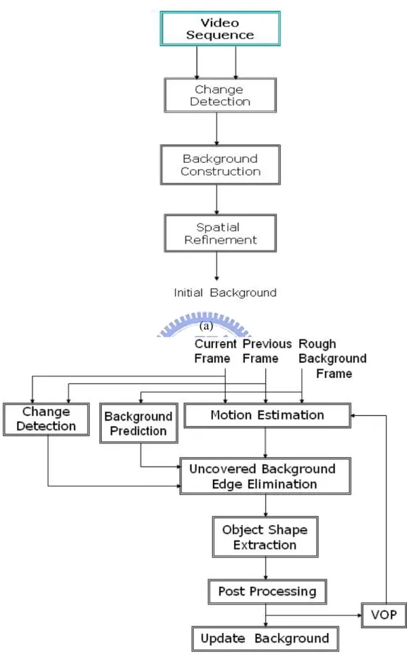
(21) Chapter 3 Video Object Segmentation Algorithm and Initial Background Construction In this chapter, a new video objects segmentation algorithm is proposed. This algorithm can be divided into initial background construction and object tracking. Unlike other change detection-based approached [9], [13], the judge criterion for moving object of this thesis does not come directly from the frame difference of two consecutive frames. We construct background information from the video sequence to find the rough information of moving objects. Any pixel that is significantly different from the rough background is assumed to be moving objects. The moving object region can be separated from other part of the scene by using rough background information. The block diagram of initial background construction is shown in Fig. 3-1(a). The goal of initial background construction is to obtain the initial background information in a video sequence. The first frame of the video sequence is general not a pure background frame. So, we need some techniques to construct initial background information in beginning of video object segmentation. In Fig. 3-1(a), we firstly detect change region with ten consecutive frames in beginning of the video sequence by using the significance test method [12], [23], [24]. According to the consecutive change detection results, pixels not changed for a long time are considerable as background pixels. However, there are some small noise regions existing in the background. We have to remove them before starting the background construction step. Then, in order to eliminate uncovered background, we combine spatial information and motion information to find the uncovered background region that is called spatial refinement process. The uncovered - 10 -.
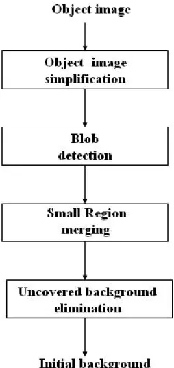
(22) (a). (b) Fig. 3-1 Block diagrams of video objects segmentation algorithm. (a) Initial background construction. (b) Object tracking. - 11 -.
(23) background problem is caused by that generated by the object moves too fast in beginning of the video sequence. This problem would result in constructing inaccurate initial background. Finally, we update background information for tracking object. The detail of initial background construction will be presented in this chapter. In Section 3.1, we introduce the change detection by using the significance method and propose a method to find the test statistic. In Section 3.2, a background construction method is proposed, In Section 3.3, we introduce how to find the spatial information and motion information, and use them to eliminate uncovered background region. Fig. 3-1(b) shows the block diagram of object tracking. We firstly detect new objects by motion estimation frame difference with current frame, previous frame and initial background frame. However, temporal changes in image intensity, non-zero frame difference, can be caused by noise or illumination drifts. We use Canny filter to eliminate the noise in background. After motion estimation, we get the edge of the moving object. Then, the uncovered background problem will appear because the background frame has not been updated yet and the object is moving. The change detection method and background prediction method are used to resolve this problem. For change detection method, if an edge pixel of the moving object does not change for a long time, it should not be a pixel of the moving object. For background prediction method, we refer to the luminance information of the background edge to predict the edge of the background. We combine these two methods to efficiently eliminate the edge of uncovered background if the background scene is not too complex. Finally, according to the binary edge information, we can extract the shape of moving object and post processing is also applied to remove the noise in the object and smooth the object boundary.. - 12 -.
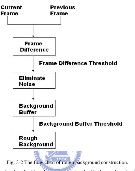
(24) 3.1 Change Detection The difference between two consecutive input frames is the basic concept of change detection. We use change detection to separate the object and the background in a frame. Obtaining rough and consistent object information is very difficult because the behavior and characteristics of the moving object vary significantly. The value of frame difference depends on the speed of object motion, background noise, and the contrast between the object and the background, etc. So, the quality of segmentation result could not be maintained consistently if the speed of the object changes significantly in the sequence. Instead of trying to segment the moving objects in the video sequence by using only two consecutive frames, this thesis focus is on the long-term behavior of the object motion to get more accurate results. In Fig. 3-2, the frame difference between current frame and previous frame, which is stored in frame buffer, is calculated and thresholded. It can be presented as the following equations: FD( x , y ,t ) =| I ( x , y ,t ) − I ( x , y ,t − 1 ) |. (3.1). FDM ( x , y ,t ) =. (3.2). 0 , If FD ≥ Th 1 , If FD < Th. where I is frame data, FD is frame difference, and FDM is frame difference mask. The frame difference threshold (Th) is needed to be set in advance. We will discuss it later. Pixels whose frame difference exceeding threshold are viewed as moving pixels. We apply some morphology tool to eliminate noise region in the background and fill up small hole in the object. Thresholding background buffer to register rough background is discussed in Section 3.2.. - 13 -.
(25) Fig. 3-2 The flow chart of rough background construction. A method related to the false alarm rate associated with change detection is used to determine the decision thresholds. We obtain the decisions by the method of hypothesis testing, in particular, by significance test. This is an appropriate approach since only the statistical properties for one hypothesis, namely that some observed temporal intensity variation is caused by noise only, are assumed to be known. The advantage of this approach is that we can specify the decision thresholds in term of false alarm rates. In order to make the decision more reliable, decisions are usually based on evaluating the set of differences inside a small decision region instead of only a single pixel. The idea behind this approach is that by taking into account a higher number samples, the overlap between the distributions of the test statistic for the cases that all - 14 -.
(26) samples are either changed or unchanged can be considerably decreased. An acceptable compromise is a window sized between 3×3 and 5×5 pixels. Frame difference algorithm used in change detection usually starts with the grey value difference image between the two frames considered. The local sum of absolute difference is computed inside a small measurement window which slides over the difference image. At each location, this local sum of absolute differences is compared against a threshold. Whenever this threshold is exceeded, the center pixel of the current window location is marked as changed. The significance test technique [12], [23], [24] is used in the proposed to obtain the threshold value. Since accumulated frame difference masks are used in the final for a reliable background, filtering or boundary relaxation is applied to the frame difference. Under the assumption that there is no change in the current pixel, the frame difference is zero-mean Gaussian distribution and its probability density function can be represented as:. P( FD | H 0 ) =. 1 2πσ 2. exp( −. FD 2 ), 2σ 2. (3.3). where FD is the frame difference of two consecutive frames and σ 2 is the variance of the frame difference. Since the camera noise is uncorrelated between different frames, the variance σ 2 is two times of the camera noise variance. H 0 denotes the null hypothesis, i.e. the hypothesis that is no change at the current pixel. The threshold value is decided by the required significance level. Their relation is shown as follows:. α = Pr ob(| FD |> Th | H 0 ),. (3.4). - 15 -.
(27) where α is the significance level and Th is the threshold value. The statistic FD is evaluated at each location on the image grid, and whenever it exceeds Th, the corresponding pixel is marked as changed, otherwise as unchanged. The significance level α may hence be interpreted as the type I error probability, that is, as the probability of rejecting H 0. although it is true.. In this method, we have to calculate the standard deviation of frame difference in the background and have to know which block is the Gaussian-like in a frame. Let the frame difference of a certain pixel in background region be a random variable d, the probability density function under the assumption of Gaussian camera noise is: f(d )=. 1. σ 2π. exp( −. −d2 ) , − ∞ < d < ∞, 2σ 2. (3.5). Only the absolute value of frame difference is concerned in background. Thus, the above equation can be rewritten as: f(d )=. 2. σ 2π ∞. α = F( d ) = ∫. exp( −. 2. d σ 2π. −d2 ) , 0 < d < ∞, 2σ 2. (3.6). − w2 )dw, 2σ 2. (3.7). exp( −. where F( d ) is the probability accumulation function of f ( d ) . In practice, the relationship between α and frame difference threshold may be stored in a look-up table. Then we estimate Gaussian-like block by partition a frame into many 8×8 blocks and choose majority of the similar standard deviations as standard deviation of camera noise. We could find the Gaussian-like block by using the Gaussian distribution with zero mean and standard deviation of camera noise.. - 16 -.
(28) We describe the steps of the change detection by using the significance test method as follows: 1. Get frame difference with current frame and previous frame. Then, the frame difference convolutes a 3×3 filter whose element is all one. We would get the local sum of each pixel to replace the original frame difference information. 2. If the maximum of the local sum of the frame difference exceeds 255, we normalize them from 0 to 255. 3. We calculate the standard deviation of frame difference in Gaussian blocks. It is believed that the standard deviation of frame difference in Gaussian blocks is very close to that of camera noise. We partition the frame difference into many 8×8 blocks and calculate standard deviation of each block. Finally, cluster these different standard deviations and choose the majority value of them as standard deviation of camera noise. We could estimate frame difference in Gaussian block as test pattern. 4. Calculate the probability density function and accumulate function. 5. Set the α value is from 0.01 to 10 −6 , and estimate frame difference threshold. 6. We get change region in which the local sum of the frame difference exceeds the threshold value.. - 17 -.
(29) (a). (b). (c). (d). (e). (f). Fig.3-3 Change detection with Salesman sequence. (a) The 1st frame. (b) The 4th frame. (c) Change detection with α =0.01, the threshold =4.5. (d) Change detection with α = 10 −6 , the threshold =7.5. (e) The standard deviation of background = 0.9369. (f) Gaussian-like blocks (white).. - 18 -.
(30) (a). (b). (c). (d). (e). (f). Fig.3-4 Change detection with Mother and daughter sequence. (a) The 1st frame. (b) The 4th frame. (c) Change detection with α =0.01, the threshold =6.5. (d) Change detection with α = 10 −6 , the threshold =10.5. (e) the standard deviation of background =1.5171. (f) Gaussian-like blocks (white). In Fig.3-3 and Fig 3-4, when α is 0.01, there is a few noise in the background and if α is 10 −6 , the noise in the background is reduced. Although the noise in background is reduced by setting α = 10 −6 , some portions of the object are removed. Therefore, α is set as 0.01 in this thesis. - 19 -.
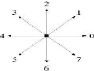
(31) After extracting change region from two consecutive frames, we have to filter the noise in the background and fill up the small holes in the object. In order to eliminate noises in the change detection, a 5×5 median filter is applied after extracting change region. The change detection result is firstly binarized. If a pixel is the change pixel, this pixel in the binary image is 1, and else is 0. Then we take a 5×5 mask passing through the binary image. If the number of the pixels whose value is one is more than the number of the pixel whose value is zero, the processing pixel of binary image is one, and else is zero. Finally, all the pixels in the binary image are iteratively processed by the same procedure and a new binary image with fewer noises is obtained. After median filter operations, small noises in the frame have been eliminated. In some case, there may be still a few large noises that median filter couldn’t reduce in the frame. We would employ the connected component filter to remove them. A simple algorithm is used to find the connected components belonging to the objects. Then, we could eliminate the noise components according to the threshold.. Fig. 3-5 The 8-direction connected component filter. 8-connectivity connected component is used to scan a difference image pixel by pixel in eight directions as shown in Fig. 3-5. Firstly, we scan the image pixel by pixel in horizontal and vertical directions (0, 2, 4, and 6). We establish vertical label buffer and horizontal label buffer. Let P denote the current pixel in the scanning process. If P is 1 and right pixel is 1, assign the same label of P to right pixel; else - 20 -.
(32) assign a new label to right pixel. Similarly, if P is 1 and bottom pixel is 1, assign the same label of P to bottom pixel, else assign a new label to bottom pixel. Then combine vertical and horizontal label buffers to establish equivalence matrix of vertical label buffer and horizontal label buffer. The details of establishing equivalence matrix will be described in Section 4.3.2. According to the equivalence matrix, we would know the equivalence class [18] in vertical label buffer or horizontal label buffer and replace each label by assigning equivalence class. Then, assign a unique label to each class, do a second scan through the image and do the similar process in diagonal directions (1, 3, 5, and 7). After labeling the object image, we count the number of pixels with same label. If the number exceeds the threshold, this label is regarded as moving object label, otherwise it is not moving object label. The results after median filtering and connected component filtering are shown in Fig. 3-6.. - 21 -.
(33) (a). (b). (c). (d). Fig. 3-6 (a) The result of median filter with respect to Fig. 3-3(c). (b) The result of median filter with respect to Fig. 3-4(c). (c) The result of connected component filter with respect to (a). (d) The result of connected component filter with respect to (b).. - 22 -.
(34) 3.2 Background Construction Background construction can extract background information from video sequences. According to FDM (frame difference mask), pixels do not move for a long time are considered as background. Defining BI is the background index and BF is the background buffer storing initial background information, the initial values of BI, BF are all set to 0.. Background index decides whether a pixel is the. background pixel or not. If BI equals background buffer threshold, the pixel is background pixel, otherwise, it is not the background pixel, as shown in Eq.(3.9) which is shown as (3.9). If a pixel is the background pixel, the pixel information of position is registered into the background buffer BF, as shown in Eq.(3.9).. BI ( x , y ,t ) =. BI ( x , y ,t − 1 ) + 1 , If FDM = 0 0. BF ( x , y ,t ) =. (3.8). , If FDM = 1. I ( x , y ,t ) , If BI ( x , y ,t ) = fth. (3.9). BF ( x , y ,t ) , If BI ( x , y ,t ) < fth. According to Eq(3.9), we set fth to 9. In ten consecutive frames, we could get nine consecutive change detection results. When the pixel is not changed in these ten frames, it is a background pixel and we would get background information. However, some holes will appear in the object if they exist in the object in nine consecutive change detection results. Therefore, the connected component filter is used to filter out the noise in object to construct initial background.. - 23 -.
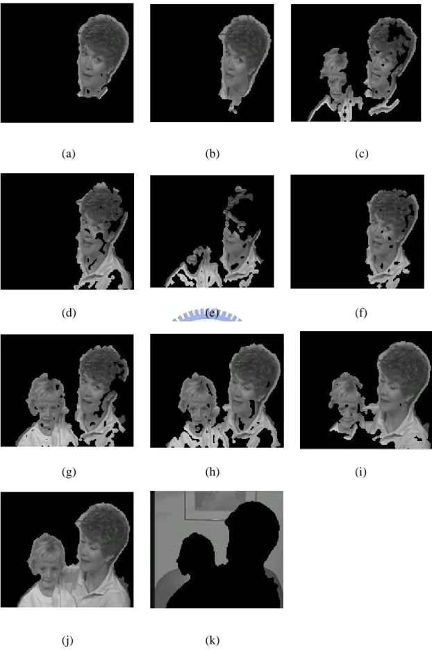
(35) (a). (b). (c). (d). (e). (f). (g). (h). (i). (j). (k). Fig. 3-7 (a) ~ (i) Nine consecutive change detection results with Salesman sequence. (j) The resultant foreground. (k) The resultant initial background.. - 24 -.
(36) (a). (b). (c). (d). (e). (f). (g). (h). (i). (j). (k). Fig. 3-8 (a) ~ (i) Nine consecutive change detection results with Mother and Daughter sequence. (j) The resultant foreground. (k) The resultant initial background. - 25 -.
(37) 3.3. Spatial. Refinement. with. Modified. Connected Component Since the information of temporal segmentation is not enough to distinguish the contour exactly and the uncovered background which does not belong to a moving object is detected as temporal changed region, we need to use the spatial information to further refine the contour. Spatial segmentation splits the entire image into homogeneous regions in terms of intensity. The different homogeneous regions are distinguished by their encompassing boundaries that can be obtained from the spatial segmentation. Choi et al. [8] proposed a method for spatial segmentation based on a morphological segmentation that utilizes morphological filters and a watershed algorithm. Although they use region merging process to avoid the over-segmentation after watershed process, the watershed process is the time-consuming for practical image process. In this thesis, a new method is proposed that partitions object image into homogeneous region by modified connected component filter and eliminates the uncovered background by the moving edge from edge operator. In stead of the connected component filter that is conventional applied to the binary images, the proposed connected component algorithm is applied to gray level images. The advantages of this algorithm not only raise the processing speed but also avoid over-segmentation too critical. The spatial refinement algorithm consists of four steps: object image simplification, modified connected component filter, region merging, uncovered background elimination. The block diagram of spatial refinement is shown in Fig. 3-9.. - 26 -.
(38) Fig. 3-9 The block diagram of spatial refinement. In the beginning of spatial refinement, the object image is simplified for ease of spatial analysis. We quantize the object image into twenty different gray level regions and use median filter to smooth the object image. Then, the local histogram analysis filter is used to remove unwanted details. Modified connected component method would partition these twenty different gray level regions into a few regions. Some small regions may be produced due to the over-segmentation problem. We need region merging method to eliminate small region. Finally, motion information could help us to find the uncovered background region.. - 27 -.
(39) 3.3.1 Object Image Simplification According to the similarly of the image, we firstly quantize the object image into different level regions. The region segmentation formula is shown as follows: ( x, y ) ∈ Ri ( x, y ) ∈ RN −1. if i[ L / N ] ≤ f ( x, y ) < (i + 1)[ L / N ], i = 0,1,..., N − 2. (3.10). if ( N − 1)[ L / N ] ≤ f ( x, y ) < L. where L means maximum gray level of the object image and N means the number of quantized level and N is twenty in this thesis. Then, we use median filter to the quantized object image. Different from the change detection step proposed in Section 3.1, the median filter is applied to the quantized gray image instead of binary image. We take a 5×5 mask passing through the quantized object image. Then we sort different level pixel in 5×5 mask into a sequence. The processing pixel is replaced by the middle pixel of the sorted sequence. Finally, all the pixels in the object image are iteratively processed by the same procedure and a new smooth object image. After median filter process, we want to remove unwanted details in texture structures of the regions. The image is homogenized in terms of region textures. So, we propose the local histogram analysis method could help spatial segmentation to obtain more semantic region for spatial segmentation. The size of structuring elements was 5×5. The processing steps of the proposed a local histogram analysis filter is described as follows: Step 1.One pixel extracted from the image is put in I33. This pixel is called the processing pixel. The other values in the filter are the quantized level of the pixels neighboring to the processing pixel.. Step 2.The pixels in the filter are arranged by their quantized level in the 5×5 mask - 28 -.
(40) shown in Fig. 3-10. The pixel has the biggest quantized level is the first pixel. The pixel has the smallest quantized level is the twenty-fifth pixel. This is a sorting procedure. Then we count the number of each quantized level. Step 3.The maximum number of the quantized level of the pixel in the arrangement is extracted to replace the original processing pixel in the image. The value of this pixel is the pixel value of the majority among twenty five pixels in the filter. Step 4.All the pixels in the image are processed from step 1 to step 3. Finally, a new image with low texture is obtained.. Fig. 3-10 5×5 mask index.. Fig. 3-17(b) shows the simplification results of gray level by using local histogram analysis method. The simplified image exhibits that detailed textures of hair and clothes of the original image are smoothed out, but the object boundaries are preserved. The size of the structuring elements is dependent on image sizes and types.. - 29 -.
(41) 3.3.2 Blob Detection with Modified Connected Component Detection of connected components between pixels in multi-level images is a fundamental step in segmentation of image object regions, or blobs. Each blob is assigned a unique label to separate it from other blobs. All the pixels within a blob of spatially connected the same quantized level are assigned the same label. It can be used to establish boundaries of objects, component of object regions, and to count the number of blobs in an image. The original algorithm was developed by Rosenfeld and Pfaltz proposed the connected component method for blob detection [25]. It performs two passes through the image. In the first pass, the image is processed from left to right and top to bottom to generate labels for each pixel and all the equivalent labels are stored in a pair of arrays. In the second passes, each label is replaced by the label assigned to its equivalence class. But, there are the problems in the second passes for large images because the equivalence arrays could become unacceptable large. The way in which label equivalences are resolved can have a dramatic effect upon the running time of this algorithm. Besides, in this thesis, we use 4-connectivity connected component filter to label the different homogeneous regions of the object. Because the object image is gray level image, the equivalence arrays become larger. Therefore, a modified connected component is proposed for gray image. We have to first to partition the simplified object frame into 8×8 blocks and apply the modified connected component filter to one block at a time as shown in Fig.3-11. Then, establish an equivalence array between these small blocks to re-label the object image. Two steps of the modified connected component are shown as follows:. - 30 -.
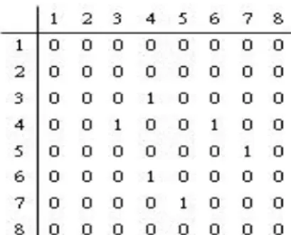
(42) Fig. 3-11 8×8 blocks in a frame. Step1. Initial labeling: This step is the same as the connected component filter to the binary image. We establish a vertical label buffer and a horizontal label buffer. Let P denote the current pixel in the scanning process. If P and right pixel are the same quantized level, assign the same label of P to right pixel, otherwise assign a new label to right pixel. Similarly, if P and bottom pixel are the same quantized level, assign the same label of P to bottom pixel, else assign a new label to bottom pixel. Then combine vertical and horizontal label buffer to establish equivalence matrix of vertical label buffer or horizontal label buffer. An example of the modified connected component is shown in Fig.3-12.. Fig. 3-12 An example of modified connected component filter. (a) The quantized image. (b) Horizontal label buffer. (c) Vertical label buffer. We would combine horizontal and vertical label information to establish equivalence matrix of horizontal label. The equivalent relations are expressed as a binary matrix. If label 3 is equivalent to 4, label 4 is equivalent to 6 and label 5 is equivalent to 7, the established matrix L is shown in Fig. 3-13. - 31 -.
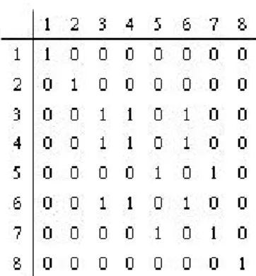
(43) Fig. 3-13 The equivalent relations matrix of horizontal label. Step 2. Resolve equivalence: Equivalence relations satisfy reflexivity, symmetry and transition. To add reflexivity in matrix L, all main diagonals are set to 1. To obtain transitive closure the Floyd-Warshall (F-W) algorithm is used. This is shown as follow: For j = 1 to n For i = 1 to n If L[i,j] = 1 then For k = 1 to n L[i,k] = L[i,k] OR L[j,k]. After applying reflexivity and the F-W algorithm, the resultant matrix L is that shown in Fig. 3-14. This algorithm can be performed in O( n 3 ) OR operations. After calculating the transitive closure, each label value is recalculated to resolve equivalences. The image is scanned again and each label is replaced by the label assigned to its equivalence class. Label 3 is equivalent to label 6. The proposed modified connected component result is shown in Fig.3-15.. - 32 -.
(44) Fig. 3-14 The resolve equivalence matrix of horizontal label.. Fig. 3-15 The result of modified connected component filter. After using modified connected component filter to all the blocks, we establish an equivalence matrix between these blocks. However, we would not process all blocks at a time for preventing large time consuming due to large label number. We would establish iteratively an equivalence matrix between each four adjacency blocks, and then re-label to these blocks. Finally, iterate this step to whole object image frame.. 3.3.3 Small Region Merging The region merging [8] is done using a graph theory. The mall regions that are smaller than pixels are selected from the spatial segmentation mask after using modified connected component filter. Each small region is then merged to its most similar region in terms of the similarity measure, consisting of motion information and gray level information, which represents how a region is closer to a neighbored - 33 -.
(45) region. Frame difference is used to get motion information. In other words, we compare the similarity measure of the region under consideration with its neighbors. Then the region under consideration is merged to the region where the difference between two similarity measures is smallest. This region merging process is repeated until no more small regions smaller than pixels do exist.. 3.3.4 Uncovered Background Regions Elimination We want to get motion information to eliminate uncovered background. In [9], hierarchical block matching is proposed for motion estimation. It finds foreground pixel, if the foot- and the top-point of the corresponding vector are both inside the changed area in the current change detection mask. If not, the pixel is set to background. Although it has a good result, the computation is complexity. Therefore, We use moving edge information in exploiting motion information of moving objects. Firstly, we get the edges of the difference frame, shown as follow:. DEn = φ (| I n−1 − I n |) = θ ( ∇G* | I n−1 − I n |). (3.11). whre the edgemaps Φ ( I ) are obtained by the Canny edge detector [11], which is accomplished by performing a gradient operation on the Gaussian convoluted image G*I, followed by applying the non-maximum( θ (.) )suppression to the gradient magnitude to thin the edge and the thresholding operation with hysteresis to detect and link edges. The difference edges are double edges information (see Fig. 3-16(b)) We need to refer to current frame edge to remove edge that belongs to previous frame. The result is shown in Fig. 3-16(c).. - 34 -.
(46) (a). (b). (c). Fig. 3-16 (a) The 13th image of Salesman sequence. (b) The difference edge. (c) The moving edge. If the moving direction of the object in beginning of video sequence is identical and moving speed of the object is too fast, comparing motion information between the first and ninth difference frame could find the uncovered background regions. The steps are described as follow. Firstly, we count the number of the pixels of the moving edge in each region. Then, if the ratio which is the sum of the edge pixels divided by the area in the region exceeds the threshold, this region is a moving region. Secondly, if the region in the first difference frame is a moving region and in the ninth difference frame is not a moving region, we called this region is candidate region of the uncovered background. Occluded regions may also be included in the candidate regions of uncovered background. Thus, we have to cluster them in these regions. The uncovered background regions are general in the outer of the change areas. So, we choose the region which is the outer region and the candidate region of the uncovered background as initial uncovered background region. Then, according to the region adjacent graph and the initial uncovered background regions, if the majority of the neighborhood of a region is initial uncovered background region, this region is regarded as uncovered background region. Finally, the whole uncovered background regions are obtained. The results are shown in Fig. 3-17.. - 35 -.
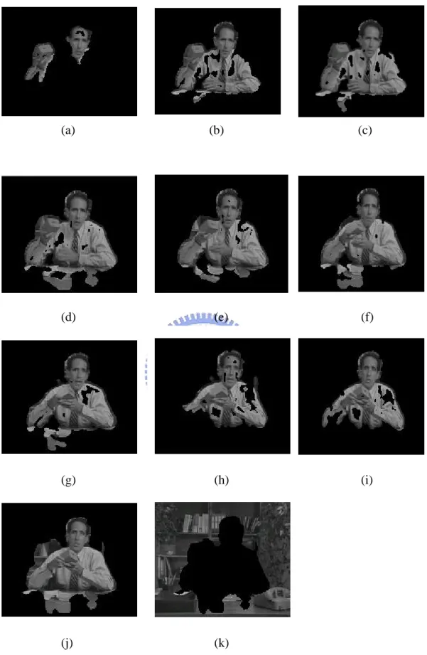
(47) (a). (b). (c). (d). (e). (f). (g). (h). (i). (k). (l). (j). (m) - 36 -.
(48) Fig. 3-17 Spatial refinement of Salesman sequence (a) The image shown in Fig. 3-7(j). (b) The simplified object image. (c) The result of blob detection. (d) The result of small region merging. (e) The moving edge in the first difference with 1st and 4th frames. (f) The moving edge in the ninth difference with 25th and 28th frames. (g) The moving regions in the first difference. (h) The moving regions in the ninth difference. (i) The candidate regions of uncovered background. (j) The initial uncovered background regions. (k) The uncovered background regions. (l) The resultant foreground. (m) The resultant initial background.. - 37 -.
(49) Chapter 4 Object Tracking The block diagram of the object tracking step has been shown in Fig. 3-1(b). The proposed edge-based motion estimation is used to detect the moving edge of the object and motion estimation could be represented as the frame difference. In this thesis, according to the previous frame, the current frame and the background frame, we could obtain completely the moving edge of the object. However, there are some scattered noises in the background of the difference image. We have to remove the noises without destroying the object contour by using previous segmented object information. Then, the uncovered background problem will appear because the background frame has not been updated yet and the object is moving. In addition, it is required for MPEG-4 coding to raise the compression ratio. Several approaches [27], [28] have been proposed to construct and update the background information from the sequence. These approaches are developed for enhancing the coding efficiency in the uncovered background region. In this thesis, the background information should be constructed with high speed for real-time application. Thus, the change detection method and background prediction method are combined to efficiently achieve this goal. Finally, according to the binary edge information, we can extract the shape of moving object and the post processing is also employed to remove the noise in the object and smooth the object boundary.. - 38 -.
(50) 4.1 Edge-Based Motion Estimation In the video object tracking, two important things should be consider. First, fast speed of tracking is required. Second, how to raise the accuracy is required also. Shape change of the moving object often happens in object tracking. The accuracy can be raised by using edge information to extract the physical change of the corresponding surface in a real scene. However, exploiting the edges of the difference frame to extract shape information of the moving objects in video sequence usually suffers from great deal of noise even in stationary background. Fig. 4-1 shows the block diagram of the proposed edge-based motion estimation algorithm. We extract the edge of the object in the current frame based on the edge maps of the difference frames and the edge map of the current frame. There are two kinds difference frames. The one is the difference frame between the current frame and the previous frame and the other is the difference frame between the current frame and the rough background frame. The edge map of difference frame between the current frame and the previous frame denoted as DE moving is the same as the moving edge presented in Section 3.3.4. The edge map of difference between the current frame and the rough background frame denoted as DE static is used to get the object edge when object does not moving. We define the edge model En as a set of all edge points detected by applying the Canny operator to the current frame and the object edge model denoted as ME belongs to En . The object edge points are not restricted to the moving object’s boundary and can be in the interior of the object boundary. The object edge models corresponding to moving edge ME moving and static edge ME static can be generated by selecting all edge pixels within small distance set. - 39 -.
(51) (a). (b) Fig. 4-1 Block diagram of the proposed edge-based motion estimation (a) changed moving edge. (b) Static moving edge. - 40 -.
(52) to be one obtained by: ME change = { e ∈ En | min || e − x ||≤ 1 } moving. (4.1). ME static = { e ∈ En || minstatic || e − x ||≤ 1 }. (4.2). x∈DE. x∈DE. There is some scattered noise which needs to be removed before extracting the shape of the video object. If Canny filter is used for edge detection, it can also remove some noise in the background, but it will result in missing the detail of the object at the same time. The process of Canny filter consists of two phases: smoothing phase and edge detection phase, and three parameters could be adjusted to control edge detection performance of Canny filter. The width of the Gaussian kernel is used in the smoothing phase, and the upper and lower thresholds are used in edge detection phase. Increasing the width of the Gaussian kernel could reduce the detector's sensitivity to noise, but it will lose some finer details in the image. If the lower threshold is set too high, it will break the noisy edge. If the upper threshold is set too low, it will increase the number of spurious and undesirable edge fragments around the object boundary. In this thesis, different upper thresholds of the Canny filter are set for the background and the previous object. The binary information of the previous moving object is passing through dilation process. Then, a larger area of previous moving object is obtained. If a pixel of the current frame exists in the larger area of previous moving object, the upper threshold is set to be low, else is set to be high. The goal of this step is to preserve the detail of the object and remove the noise in background at the same time. The dilation is a morphological operation [29] and it is a morphological - 41 -.
(53) transformation that combines two sets by set union. With predefined sets B and S, the dilation of B by S for extended the binary area of the object is defined as: ∧. D( B , S ) = { x | ( S )x ∩ B ≠ φ }. (4.3). Similarity, there is erosion operation which is a morphological transformation that combines two sets by using set subtraction. With predefined sets B and S, the erosion of B by S is defined as: E( B , S ) = { x | ( S )x ⊆ B }. (4.4). where the S is processed binary image and B is structuring element.. - 42 -.
(54) 4.2 Uncovered Background Edge Elimination with. Change. Detection. Module. and. Background Prediction Module In Fig. 4-1(a), the uncovered background edge can be removed by referring to the edge information of the current frame. However, in Fig. 4-1(b), the uncovered background edge could not be easily removed because the background has not been updated yet. In change detection module, shown in Fig.3-1(b), according to the FDM (frame difference mask), if a pixel of the static edge map does not change for a long time, it should not be considered as an edge pixel of the moving object. Because the initial background has been constructed, the background information is known. In other words, we could quickly get the noise standard deviation. Then, we would not calculate the probability density function. We directly multiply noise standard deviation std noise with a fixed tracking weight weight tracking as the difference frame threshold Thtracking as shown in Eq.(4-5). The tracking weight weight tracking could be derived by choosing the largest weight in the nine change detection results in Section 3.1. The weight in change detection is the difference frame threshold divided by the noise standard deviation.. Thtracking = std noise * weight tracking. (4.5). If the difference pixel is smaller than Thtracking , the pixel of the frame difference mask is zero, else is one. Then, if the pixel of the static edge map is not the change region, the pixel of edge index (EI) adds one as follows:. - 43 -.
(55) EI ( x , y ,t ) =. EI ( x , y ,t − 1 ) + 1 , If FDM ( x , y ,t ) = 0 & ME static ( x , y ,t ) = 1 (4.6) 0 , otherwise. Then, if the pixel of the edge index exceeds the threshold ( fth ) as shown in Eq(3.9), we set the pixel of the static edge map is not the edge pixel of the moving object as follows:. ME static ( x , y ,t ) =. 0 , If EI ( x , y ,t ) ≥ fth 1 ,otherwise. (4.7). In the background prediction module, we assume the background is not complex and then we could decide whether a pixel of the static edge map is background edge or not by using gray level information. If gray level of a pixel of the static edge map is similar to a pixel of the background edge map around that pixel, that pixel is a background edge pixel. The operation steps of background prediction module are summarized as follows: Step 1. We have 5×5 static edge map, 5×5 background edge map and 5×5 index maps as shown Fig.4-2(a),(b) and (c), respectively. Then, we start the processing of background prediction method when a pixel of the static edge map is around a pixel of the background edge map.. (a). (b). (c). Fig. 4-2 Background prediction (a) Static edge map. (b) Background edge map. (c) Index map.. - 44 -.
(56) Step 2. We compare the gray levels of 9 (3×3 mask) neighbor pixels of P33 in static edge map with gray levels of 9 (3×3 mask) neighbor pixels of P32 in background edge map. Step 3. If the difference of the gray levels between these two masks is small, P33 of static edge map is not an edge pixel of the moving object. Step 4. All the pixels in the static edge map are processed by step 1 to step 3 and uncovered background problem could be resolved. In summary, combining the change detection module and background prediction module could more efficiently eliminate uncovered background edge than only using change detection module. If the background is complex, only the change detection module could work. But, the background prediction module sometimes could work where the luminance of the object and the background is similar. Therefore, the change detection module and background prediction module are combine to get the best performance in various situation. It will be demonstrated in Chapter 5.. - 45 -.
(57) 4.3 Object Shape Extraction After getting binary edge information of the moving object, we will extract the shape of the moving object. Since some noise edge may still exist in background and shape extraction is large time consuming process when the frame size is large, in this thesis, we use vertical projection and horizontal projection to find the adapted rectangle covering the moving object and the noise will not affect the performance of the extracting moving object. In vertical projection as shown in Fig.4-3(b), we count the edge pixels number of the same column in edge image of the moving object. Assume I(x,y) is the edge pixel of the image, the vertical projection on the image is. V ( x ) = ∑ 1 if I ( x , y ) ∈ edge pixels. (4.8). y. If one image contains 144 columns, it also has 144 vertical projection values. We set a threshold and check each projection value from first column to the last one. If the projection value is lager than the threshold, there is moving object information in that column. In order to avoid noises in the image, the threshold is 2 in our experiments. After vertical projection on edge image, we can obtain start position Xstart and end position Xend of the moving object on x-axis. We get the moving object from Xstart to Xend. Similarly, we count the edge pixels number of the same row on this edge image. This is called horizontal projection as shown in Fig.4-3(c). The horizontal projection on the image is. H ( y ) = ∑ 1 if I ( x , y ) ∈ edge pixels. (4.9). x. After horizontal projection, we can obtain start position Ystart and end position - 46 -.
(58) Yend of the moving object on y-axis. Finally, we get a rectangular image from left-top coordinate (Xstart, Ystart) to right-bottom coordinate (Xend, Yend) in the edge image as shown in Fig.4-3(d). The edge information of the moving object is included in the black rectangular.. (d) Fig. 4-3 The localization result of the object edge. (a) The edge of the moving object. (b) Vertical projection. (c) Horizontal projection. (d) Black rectangle including the edge of the moving object.. - 47 -.
(59) According to this black rectangle shown in Fig.4-3(d), we extract the shape of the moving object. The horizontal candidates are declared to be the region inside the first and last edge points in each row (see Fig. 4-4(a)) and the vertical candidates for each column (see Fig. 4-4(b)]. After finding both horizontal and vertical VOP candidates, intersection regions (see black regions in Fig. 4-4(c)) through logical AND operation on horizontal and vertical VOP candidates are further processed by morphological operations (see Fig. 4-4(d)).. (a). (b). (c). (d). Fig. 4-4 Object shape extraction. (a) Horizontal candidate. (b) Vertical candidate. (c) Intersection region. (d) The resultant VOP.. - 48 -.
(60) 4.4 Post Processing In our approaches, we could segment moving object accurately and the noise in background could be eliminated completely. However, we sometimes lack the moving edge where the gray levels between the foreground and the background are too similar. It results in a hole in contour of the moving object. So, after extracting the shape of the moving object, we use closing operation to fill up the hole in object region. The closing operation is the erosion operation followed by the dilation operation on an image and the closing of B by S is defined as:. C( B , S ) = E( D( B , S )). (4.10). The structuring element is 3×3 mask and the mask size cannot be too large because it would affect the smooth of the object boundary and the details of the shape information. However, noise region whose areas are sometimes larger than structuring element could not be removed by the closing. So, we firstly iterate the dilation operation step, shown in Eq.(4.10), until the noise in the object is removed and then iterate the erosion operation step by the same times of the dilation step. In addition, there is small sharp object contour when some noises exist near the object. In order to eliminate small sharp, we use opening operation whose structuring element is also 3×3 mask. The opening operation is dilation operation followed by erosion operation on an image. The opening of B by S is defined as:. O( B , S ) = D( E( B , S )). (4.11). - 49 -.
(61) Chapter 5 Experiment results Two types of video sequences, the MPEG4 standard test files and the videos shot by the digital camera, are used to test the performance of the proposed method. The MPEG4 standard test files including Akiyo, Claire, Hall monitor, Mother and daughter and Salesman sequences are QCIF/CIF with YUV format. The Jack video sequence and Frank video sequence are 320×240 with RGB format. The programs are implemented in C language and executing on a Pentium IV 1.8 GHz system under Microsoft Windows XP operation system.. The qualitative performance evaluation is divided into three stages and it is given in Section 5.1:. 1. Initial object construction: In beginning ten frames of the video sequences, we construct initial background by thresholding background buffer. If a pixel is not changed during ten frames, the pixel is background pixel. Besides, we need spatial refinement method to eliminate uncovered background region when the object is moving too fast.. 2. VOP extraction: Motion estimation with Canny filter is used to detect the object edge and use adaptive threshold to preserve object and remove the noise in the background. Then, we extract VOP by using the logical AND method passing through horizontal and vertical candidates.. 3. Background updating: According to the VOP extracting result, we update the background frame. We could observe some changes in the background frame.. - 50 -.
數據
+7


相關文件
In summary, the main contribution of this paper is to propose a new family of smoothing functions and correct a flaw in an algorithm studied in [13], which is used to guarantee
IQHE is an intriguing phenomenon due to the occurrence of bulk topological insulating phases with dissipationless conducting edge states in the Hall bars at low temperatures
Structured programming 14 , if used properly, results in programs that are easy to write, understand, modify, and debug.... Steps of Developing A
n The information contained in the Record-Route: header is used in the subsequent requests related to the same call. n The Route: header is used to record the path that the request
In the work of Qian and Sejnowski a window of 13 secondary structure predictions is used as input to a fully connected structure-structure network with 40 hidden units.. Thus,
The remaining positions contain //the rest of the original array elements //the rest of the original array elements.
synchronized: binds operations altogether (with respect to a lock) synchronized method: the lock is the class (for static method) or the object (for non-static method). usually used
The pipelined CORDIC arithmetic unit is used to compute the complex multiplications involved in FFT, and moreover the required twiddle factors are obtained by using the
