Optimal design of loudspeaker arrays for robust cross-talk
cancellation using the Taguchi method and the genetic algorithm
Mingsian R. Bai,a)Chih-Wei Tung, and Chih-Chung Lee
Department of Mechanical Engineering, National Chiao-Tung University, 1001 Ta-Hsueh Road, Hsin-Chu 300, Taiwan, Republic of China
共Received 10 August 2004; revised 13 December 2004; accepted 7 February 2005兲
An optimal design technique of loudspeaker arrays for cross-talk cancellation with application in three-dimensional audio is presented. An array focusing scheme is presented on the basis of the inverse propagation that relates the transducers to a set of chosen control points. Tikhonov regularization is employed in designing the inverse cancellation filters. An extensive analysis is conducted to explore the cancellation performance and robustness issues. To best compromise the performance and robustness of the cross-talk cancellation system, optimal configurations are obtained with the aid of the Taguchi method and the genetic algorithm共GA兲. The proposed systems are further justified by physical as well as subjective experiments. The results reveal that large number of loudspeakers, closely spaced configuration, and optimal control point design all contribute to the robustness of cross-talk cancellation systems共CCS兲 against head misalignment. © 2005 Acoustical Society of America. 关DOI: 10.1121/1.1880852兴
PACS numbers: 43.38.Vk关AJZ兴 Pages: 2802–2813
I. INTRODUCTION
Spatial audio or three-dimensional 共3D兲 audio has re-ceived much attention in many emerging applications such as computer multimedia, home theater, video games, digital television, etc. Despite the rapid development of the technol-ogy, cross talk has been a plaguing problem when loudspeak-ers are used as the means of rendering. Binaural audio sig-nals containing directional cues are to be reproduced, at the ears of a listener, that he or she would naturally hear. How-ever, excess cross talk can smear these cues and adversely effect the localization of sound images reproduced by loud-speakers. It is thus desirable to preprocess the loudspeaker signals by using the so-called cross-talk cancellation system 共CCS兲 so that the sound from the loudspeakers to contralat-eral ears is minimized, if not completely eliminated.
Several CCS have been proposed in the past. The idea of CCS was first introduced by Bauer,1 and later put into prac-tice by Atal and Schroeder,2and Damaske and Mellert.3The limitation of these early systems is that head movement away from the sweet spot greater than about 75 to 100 mm would significantly degrade the spatial effect. Cooper and Bauck suggested a propagation matrix based on the spherical head model.4A similar method by Gardner approximates the ef-fect of the head with a low-pass filter, a delay, and a simple gain.5Blumlein,6and Cooper and Bauck7,8showed that, un-der the assumption of left–right symmetry, a ‘‘shuffler’’ filter can be used to simplify the implementation of CCS. Note that, if the position of the listener changes over time, then ipsilateral and contralateral transfer function will not be sym-metrical, but will vary to reflect the head-related-transfer functions 共HRTF兲 for the listener’s new position. A head-tracking CCS was reported in the work of Kyriakakis et al. to cope with head movement of the listener.9,10 Ward and
Elko in Bell Labs have conducted a series of less elaborate but insightful analysis of the robustness of the CCS. In their first paper11 on this topic in 1998, robustness of a simple 2⫻2 CCS was investigated using weighted cancellation per-formance measure 共at the pass zone and stop zone, respec-tively兲. In their second paper12in 1999, robustness of a 2⫻2 CCS was again examined using a different measure that fo-cuses more on numerical stability, as reflected by matrix con-dition numbers, with respect to data and/or system perturba-tions during matrix inversion. Both approaches wind up with optimal loudspeaker spacing inversely proportional to fre-quency. Parallel to the previous work, the present paper ex-plores the robust issue in a more general context. Using mul-tidrive array configurations, more than two loudspeakers are used to provide additional degrees of freedom for control of the sound field. In the optimization procedure, channel sepa-ration and beamwidth are employed as a more intuitive ro-bustness measure against head misalignment. The optimiza-tion leads to an optimal loudspeaker configuration independent of frequency. An alternative approach was de-veloped by Takeuchi and Nelson to enhance the robustness of CCS against head movement away from the sweet spot. In their system, two loudspeakers are closely spaced to form what they call the ‘‘stereo dipole.’’13 This idea was further extended by the same researchers to be the optimal source distribution 共OSD兲 system.14 Their robust analysis of CCS was also based on numerical stability in relation to the errors in matrix inversion. The performance of CCS deteriorates due to these errors resulting possibly from head misalign-ment and the HRTF modeling variations. Inversion of an ill-conditioned system 共with a large matrix condition num-ber兲 leads to loss of dynamic range and lack of robustness to head misalignment. The authors attempt to pinpoint an opti-mal configuration of a 2⫻2 CCS in which loudspeaker spac-ing is the primary design parameter such that the trade-off among dynamic range, robustness, and control performance
are best reconciled. Their analysis also yielded optimal loud-speaker spacing inversely proportional to frequency. Since the spacing thus found is frequency dependent, a multidrive configuration of the OSD, comprising pairs of loudspeakers with different spacing, was suggested to deal with cross-talk cancellation in different frequency bands. Apart from the ro-bustness measure and analysis techniques, the present paper differs from their approach in that our approach is a direct multidrive共more than two loudspeakers兲 array configuration, which requires no crossover circuits that may introduce dis-tortions at the crossover frequencies. In this array configura-tion, the additional degrees-of-freedom in control of sound field provided by the beamformer can be exploited to the greatest extent.
In this paper, the performance and robustness issues of CCS for various loudspeaker configurations are examined. Traditional stereo CCS systems require that the listener is positioned in the so-called ‘‘sweet spot’’ such that the listener forms an equilateral triangle with respect to the loudspeaker pair. The loudspeakers, therefore, subtend an angle of 60° from the listener.15 Once the listener moves away from the sweet spot, especially when moving sideway, the conditions for cancellation are no longer met and the spatial sound im-ages are lost. The idea of sweet spot applies with different degrees not only to stereo systems but also to other loud-speaker configurations.
Following the analysis of performance and robustness analysis, this paper is focused on the development of a CCS using a loudspeaker array in an effort to best compromise performance and robustness of the system. An array focusing scheme is also exploited, based on the inverse propagation operator that relates the transducers to a set of chosen control points.16,17Optimal design parameters of the array are found using the Taguchi method18 and the genetic algorithm 共GA兲.19,20
It has been found in Refs. 11 and 13 that cancel-lation is least effective because of the narrow sweet spot as the head moves sideway rather than when it moves in the other directions. Hence, only lateral misalignment is investi-gated in the present paper. As will be detailed later, the op-timal configuration is the closely spaced array. Such system is found to be more robust to misalignment of the listener’s head. This finding is in agreement with the conclusion of Ref. 21. The 3D audio system resulting from the above-mentioned optimization is then implemented on a multime-dia Pentium 4 personal computer. The proposed systems are further justified by physical and subjective experiments. Fea-sibility of the proposed CCS will be discussed in the conclu-sions.
II. THEORY AND METHODS A. The propagation matrix
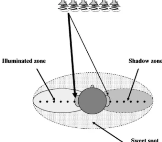
Assume that the process of sound propagation from the loudspeakers to the listener’s ears is linear and time invari-ant. Viewed as a multichannel system, a propagation matrix relates the loudspeaker inputs and a set of chosen ‘‘control points.’’ These control points are allocated along the line linking two ears, as shown in Fig. 1. These control points are crucial to the tailoring of the so-called sweet spot, which is
composed of an illuminated zone for the ipsilateral propaga-tion and a shadow zone for the contralateral propagapropaga-tion. The main purpose of a CCS is to minimize, if not completely eliminate, the cross talks associated with the contralateral propagation. To accomplish this, therefore, unity gains are designated to the control points in the illuminated zone, whereas nulls are designated to the control points in the shadow zone. For simplicity, we restrict ourselves to a one-dimensional array and define head-related impulse responses 共HRIR兲, hm j(n), 1⭐m⭐M, 1⭐ j⭐J, as the impulse
re-sponses corresponding to the mth control point and the jth loudspeaker 共n being the discrete-time index兲. Let vj(n), 1 ⭐ j⭐J, be the J input signals to the loudspeaker array. The output signals fm(n), 1⭐m⭐M, received at the control
points are given by
fm共n兲⫽
兺
j⫽1 Jhm j共n兲*vj共n兲, 1⭐m⭐M, 共1兲
where*denotes the convolution operator. Fourier transform of this equation leads to
Fm共ej兲⫽
兺
j⫽1J
Hm j共ej兲Vj共ej兲, 1⭐m⭐M. 共2兲
In matrix form
f共ej兲⫽H共ej兲v共ej兲, 共3兲
with v(ej)⫽关Vj(ej)兴1⭐ j⭐J and f(ej)
⫽关Fm(ej)兴1⭐m⭐M being the column vectors of the Fourier transforms of the loudspeaker input signals and the repro-duced signals, respectively. Overall, the transfer matrix
H(ej)⫽关Hm j(ej)兴1⭐m⭐M,1⭐ j⭐J represents the frequency-domain multichannel propagation process from the array loudspeakers to the control points at the sweet spot.
B. Inverse filtering with Tikhonov regularization
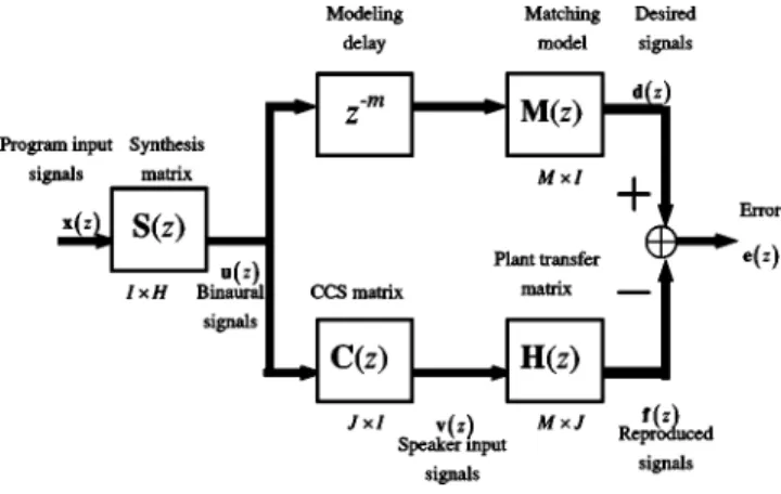
The CCS aims to cancel the cross talks in stereo loud-speaker rendering so that the binaural signals are reproduced at two ears like those from a headphone. This can be viewed as a model-matching problem, shown in Fig. 2. In the block diagram, x(z) is a vector of H program input signals共z being the z-transform variable兲, u(z) is a vector of I⫽2 binaural
signals, v(z) is a vector of J loudspeaker input signals, f(z) is a vector of M reproduced signals, d(z) is a vector of M desired signals, and e(z) is a vector of M error signals. M(z) is an M⫻I matrix of matching model, H(z) is an M⫻J plant transfer matrix, and C(z) is a J⫻I matrix of the CCS filters. The term z⫺m accounts for the modeling delay to ensure causality of the CCS filters. It is straightforward to establish the following relationships:
v共z兲⫽C共z兲u共z兲, 共4兲
f共z兲⫽H共z兲v共z兲, 共5兲
d共z兲⫽z⫺mM共z兲u共z兲, 共6兲
e共z兲⫽d共z兲⫺f共z兲. 共7兲
Ideal model matching requires that H(z)C(z)⫽z⫺mM(z). In
general, H(z) is noninvertible because it is usually ill-conditioned and even nonsquare. To overcome this difficulty, we employ the Tikhonov regularization procedure in the ma-trix inversion process.22 In the method, one seeks to mini-mize a frequency-domain objective function O(ej) defined as
O共ej兲⫽eH共ej兲e共ej兲⫹2vH共ej兲v共ej兲. 共8兲
The regularization parameter weighs the input power vHv
against the performance error eHe. The optimal solution vopt(ej) of Eq.共8兲 is
vopt共ej兲⫽关HH共ej兲H共ej兲
⫹2I兴⫺1HH共ej兲M共ej兲u共ej兲. 共9兲
Consequently, the CCS matrix can be readily identified as
C共ej兲⫽关HH共ej兲H共ej兲⫹2I兴⫺1HH共ej兲M共ej兲.
共10兲 In our approach, the parameteris frequency dependent and constrained by a gain threshold applied to C(ej), e.g., 12 dB. This is in contrast to the approach in Ref. 16, where a constantapplied to all frequencies.
Traditionally, the desired signals d(z) are just the binau-ral signals u(z). The matrix M(z) is an identity matrix of order 2, i.e., M⫽I, and the frequency responses of the cor-responding optimal filters are given by
C共ej兲⫽关HH共ej兲H共ej兲⫹2I兴⫺1HH共ej兲. 共11兲
The frequency response matrix C(ej) is then sampled at N c
equally spaced frequencies with discrete-frequency index k
C共k兲⫽关HH共k兲H共k兲⫹2I兴⫺1HH共k兲, k⫽1,2,...,Nc. 共12兲 The impulse responses of the inverse filters can be calculated using the inverse fast Fourier transform 共IFFT兲 of the fre-quency samples of Eq. 共12兲 with appropriate windowing. Circular shifts may be necessary to guarantee the causality of CCS filters; hence, the modeling delay z⫺m in Fig. 1.
The present method differs from the foregoing conven-tional approach in that, instead of ‘‘single-point’’ matching, a number of control points are distributed in the illuminated zone and the shadow zone so that the sweet spot can be widened. This is accomplished by choosing a more complex matching model akin to the window design in the time-domain digital signal processing. An example of choosing control points is illustrated as follows. Suppose we wish to choose three points in the illuminated zone and six points in the shadow zone for each ear. These control points can only be located at six discrete locations on each side of the head, as shown in Fig. 1. In this scenario, we may choose a 9⫻1 matching model for the left ear with the following pattern:
ML⫽关1 1 1 0 0 0 0 0 0兴T, 共13兲
where the subscript L stands for the left ear, and the ones and zeros correspond to the designated control points in the illu-minated zone and the shadow zone, respectively. Hence, the desired signal for the left ear is
dL⫽z⫺mMLu⫽z⫺m关uL uL uL 0 0 0 0 0 0兴T. 共14兲 After the matching model is selected, the optimal CCS filters can be calculated according to Eq.共10兲. The same procedure applies to the ear on the right side. In general, more points in the shadow zone are needed than in the illuminated zone, since the performance in the former region is more critical to cancellation of cross talks. It should be noted that the in-creased complexity of the sweet spot widening technique lies purely in the off-line design procedure. The number of chan-nels (J⫻I) of the resulting CCS filter remains the same.
III. OPTIMIZATION OF ARRAY CONFIGURATION FOR ROBUST CROSS-TALK CANCELLATION
Many design factors are involved in the CCS, e.g., array configurations, spacing and positions, number of control points in filter design, and so forth. Different configurations have effects with varying degree on the performance as well as robustness of the CCS. To minimize the effort of trial and error, a systematic design procedure of CCS based on the Taguchi method and the genetic algorithm共GA兲 is presented as follows.
A. Taguchi method
The Taguchi method is an experiment design procedure well suited to multivariable optimization. The method is in-tended for three engineering applications: system design, pa-rameter design, and tolerance design. For our optimization
FIG. 2. The block diagram of a multichannel model-matching problem in the CCS design.
problem at hand, we focus primarily on the parameter design with application in determining array configuration.
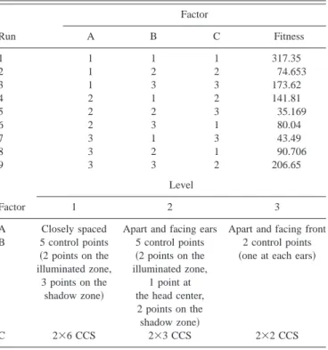
The greatest benefit of using the Taguchi method is that, instead of an exhaustive search, much fewer experiments are required in search of the optimal combination of design pa-rameters. This is accomplished by means of orthogonal ar-rays which are based on statistical experimental design theory. To illustrate, we consider three factors and three lev-els problem. Assume that no interactions exist and the varia-tion is very small in each observavaria-tion. The orthogonal array, denoted as L9(33), is shown in Table I, where the numbers 1–3 correspond to three discrete levels of the design factors. According to the table, only nine runs of experiment are required, which is fewer than original 27 searches. The
L9(33) orthogonal array is applied to the design of a robust CCS. The parameters to optimize include共A兲 the configura-tions of loudspeaker arrays; 共B兲 the distribution of the con-trol points; and 共C兲 the dimension of the CCS matrix. As shown in Fig. 3, the factor共A兲 is categorized into three lev-els: 共A1兲 represents the case in which the loudspeakers are closely spaced 共six loudspeakers in a row兲; 共A2兲 represents the case in which two three-element loudspeaker arrays are wide apart共subtending 60°兲 and facing the ears; 共A3兲 repre-sents the case in which two three-element loudspeaker arrays are wide apart 共subtending 60°兲 and facing the front. The factor共B兲 is categorized into three levels: 共B1兲 represents the case of five control points in which two points are placed in the illuminated zone and three points are placed in the shadow zone;共B2兲 represents the case of five control points in which two points are placed in the illuminated zone, one point is placed at the center of the head with 0.5 weighting, and two points are placed in the shadow zone; 共B3兲 repre-sents the case of two control points in which one point is placed at the ipsilateral ear and one point is placed at the
contralateral ear. As shown in Fig. 4, the factor 共C兲 is cat-egorized into three levels.共C1兲 represents the case of a 2⫻6 CCS in which six loudspeakers are driven with different sig-nals to reproduce the binaural sigsig-nals共12 filters are needed兲. 共C2兲 represents the case of a 2⫻3 CCS in which only a three-element array is considered in the CCS design to focus on the ipsilateral ear and nullify the beam at the contralateral ear loudspeakers. The 2⫻3 CCS design procedure is applied to each side of the ear to reproduce the binaural signals共six filters are needed兲. 共C3兲 represents the case of a 2⫻2 CCS in which only two stereo loudspeakers are driven with different signals to reproduce the binaural signals 共four filters are needed兲.
Both performance and robustness are considered with appropriate weighting W in the objective function
f⫽performance⫹W⫻robustness. 共15兲
To assess the performance and robustness, the channel sepa-FIG. 3. Three configurations of loudspeaker arrays.共a兲 closely spaced loud-speakers共six loudspeakers in a row兲; 共b兲 two wide-apart three-element loud-speaker arrays共subtending 60°兲, facing the ears; 共c兲 two wide-apart three-element loudspeaker arrays共subtending 60°兲, facing the front.
TABLE I. Parameter design using the orthogonal array of the Taguchi method. Nine observations and three factors for three levels are required.
Run Factor A B C Fitness 1 1 1 1 317.35 2 1 2 2 74.653 3 1 3 3 173.62 4 2 1 2 141.81 5 2 2 3 35.169 6 2 3 1 80.04 7 3 1 3 43.49 8 3 2 1 90.706 9 3 3 2 206.65 Factor Level 1 2 3
A Closely spaced Apart and facing ears Apart and facing front B 5 control points 共2 points on the illuminated zone, 3 points on the shadow zone兲 5 control points 共2 points on the illuminated zone, 1 point at the head center, 2 points on the shadow zone兲
2 control points
共one at each ears兲
ration is calculated using the interaural transfer functions 共ITFs兲 ITFL⫽ HLR HLL , ITFR⫽ HRL HRR , 共16兲
where HLR and HRL are the contralateral frequency re-sponses; HLL and HRR are the ipsilateral frequency
re-sponses. The performance function is defined as the channel separation at the nominal position, and the robustness func-tion is defined as the lateral beamwidth when the channel separation drops below⫺20 dB. The lower the channel sepa-ration, the better is the performance of cross-talk cancella-tion. The larger the beamwidth, the more robust is the CCS
against lateral misalignment of the listener’s head. The re-sults with the weighting W⫽10 are summarized in Table II. From Table II, the optimal parameters 共with maximum val-ues of objective function兲 of the robust CCS are found to be closely spaced arrays, five control points 共two points on the illuminated zone, three points on the shadow zone兲, and a 2⫻6 CCS matrix.
B. The genetic algorithm
The above-mentioned Taguchi method is more suited to design parameters with finite number of discrete levels. In
FIG. 4. The dimension of the CCS matrix.共a兲 a 2⫻6 CCS in which six loudspeakers are driven with different signals to reproduce the binaural sig-nals.共b兲 a 2⫻3 CCS in which only a three-element array is considered in the CCS design to focus on the ipsilateral ear and nullify the beam at the contralateral ear loudspeakers. The 2⫻3 CCS design procedure is applied to each side of the ear to reproduce the binaural signals. 共c兲 a 2⫻2 CCS in which only two stereo loudspeakers are driven with different signals to reproduce the binaural signals共four filters are needed兲.
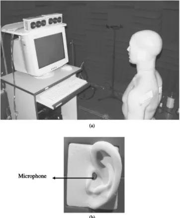
FIG. 5. The photo of the experimental arrangement.共a兲 The robust CCS with an loudspeaker array.共b兲 The 1/2-in. condenser microphone embedded in the manikin’s ear.
TABLE II. The results of optimal parameters obtained using the Taguchi method. The numbers in the second column are obtained by summing the fitness functions of the corresponding parameter levels. The optimal combi-nations of parameters of the robust CCS are closely spaced loudspeakers, five control points共with two points on the illuminated zone, three points on the shadow zone兲, and with an 2⫻6 CCS matrix.
Levels of
parameters Average of objective function Chosen level A1 317.35⫹74.653⫹173.62⫽565.623 Closely spaced A2 141.81⫹35.169⫹80.04⫽257.019 A3 43.49⫹90.706⫹206.65⫽340.846 B1 B2 B3 317.35⫹141.81⫹43.49⫽502.65 74.653⫹35.169⫹90.706⫽200.528 173.62⫹80.04⫹206.65⫽460.31 5 control points 共2 points on the illuminated zone, 3 points on the shadowzone兲 C1 317.35⫹80.04⫹90.706⫽488.096 2⫻6 CCS C2 74.653⫹141.81⫹206.65⫽423.113 C3 173.62⫹35.169⫹43.49⫽252.279
the sequel, an alternative approach that is useful for optimi-zation of continuous parameters is exploited to find the best configuration of the CCS.
1. Encoding and decoding
In the method of GA, all parameters are encoded into binary strings called the chromosomes. The resolution of a parameter is dependent on the amount of bits per string and search domain. For instance, we wish to find the optimal spacing x苸关Umin,Umax兴 (Umin and Umax being the lower limit and the upper limit of the search space兲 of the loud-speaker array. This parameter is then mapped to an unsigned integer in 关0,2l兴, where l is the number of bits. Thus, the resolution of this coding scheme is
⌫⫽Umax⫺Umin
2l⫺1 . 共17兲
2. Fitness evaluation
In the GA optimization, the objective one seeks to achieve is termed the fitness function. A chromosome with high fitness has higher probability to survive the natural se-lection and reproduce offspring in the next generation. The fitness function is the performance function共channel separa-tion兲 and the robustness function 共beam width兲 with appro-priate weighting W
f⫽performance⫹W⫻robustness. 共18兲
3. Reproduction, crossover, and mutation
Reproduction directs the search of GA towards the best
individuals. During the process, the reproduction probability of the chromosome is determined by the fitness function. First, the chromosome of the present population is repro-duced in the next generation according to the reproduction probability Si Si⫽ fi 兺k⫽1 Pl f, 共19兲
where Plis the population size.
Crossover exchanges the contents of chromosomes via
probabilistic decision in the mating pool. It is done in three steps. First, the crossover ratio Cr is defined 共in general,
FIG. 6. Illustrations of four loudspeaker array configurations.共a兲 Configu-ration 1: closely spaced 2⫻2 CCS. 共b兲 Configuration 2: wide apart 共subtend-ing 60°兲 2⫻2 CCS. 共c兲 Configuration 3: closely spaced 2⫻6 CCS. 共d兲 Con-figuration 4: wide-apart共subtending 60°兲 2⫻6 CCS.
FIG. 7. The contour plots of beam patterns at 1 kHz of various CCS configurations.共a兲 Configuration 1. 共b兲 Configuration 2. 共c兲 Configuration 3. 共d兲 Configuration 4.共e兲 Configuration 3 with the optimal 2⫻6 CCS obtained in the GA procedure.
0.8⭐Cr⭐1 and we choose Cr⫽0.85) and two chromosomes
in the present population are selected randomly. Second, a splice point at the chromosomes is selected randomly. Third, the chromosomes codes after the splice point are inter-changed.
Normally, the chromosomes become increasingly homo-geneous as one particular gene begins to dominate after sev-eral generations and eventually leads to premature conver-gence. To obviate this problem, mutation is introduced into the GA procedure. Let the mutation ratio be Mr 共in general, 0⭐Mr⭐0.01 and we choose Mr⫽0.008). The mutation point is determined randomly and carried out by alternating the gene from zero to 1, or vice versa. Note, however, that mutation should be used sparingly. The GA would behave like a random search if the mutation rate were too high.
The aforementioned GA procedure was applied to opti-mize the design of the robust CCS. The design parameters we wish to optimize are similar to those in the Taguchi method, i.e., the spacing between loudspeaker arrays, the dis-tribution of the control points, and the dimension of CCS matrix. When the robustness weighting of fitness function is
set to be 1, the optimal design parameters of the robust CCS obtained with the aid of the GA procedure are 0 cm spacing 共closely spaced arrays兲, six control points 共one point in the illuminated zone and five points in the shadow zone兲, and a 2⫻6 CCS matrix. This result is consistent with the optimal configuration obtained previously using the Taguchi method.
IV. NUMERICAL AND EXPERIMENTAL INVESTIGATIONS
In the paper, the performance of CCS and the associated robustness against head misalignment is examined via nu-merical and experimental investigations. Only lateral mis-alignment is considered because it affects the performance of the CCS more significantly than the other types of misalignment.23,24The objective performance index is chan-nel separation as defined previously. The experimental ar-rangement is shown in Fig. 5. A loudspeaker array is mounted on a computer monitor. The distance between the array and the manikin is 80 cm. The loudspeaker array is 10 cm higher than the ears of the manikin. A 1/2-in. condenser FIG. 8. Channel separations of the left ear obtained using the 2⫻2 CCS for the wide-apart configurations. The solid lines represent the natural separations and the dotted lines represent the separations with cross-talk cancellation.共a兲 The channel separation with no displacement. 共b兲 The channel separation with 5-cm displacement to the left.共c兲 The channel separation with 10-cm displacement to the left. 共d兲 The channel separation with 15-cm displacement to the left.
microphone is fitted inside the ear of the manikin. The sam-pling rate is 51.2 kHz. The CCS matrix of inverse filtering is calculated by using Eq.共10兲. The length of each filter is 512 samples and the modeling delay m is 256 samples. The
overlap-add method is employed to perform block
convolu-tion efficiently.25
A. Numerical simulations
Before embarking on the experimental investigations, a numerical simulation is carried out to gain more insights into the loudspeaker array configurations in relation to the robust-ness issue of the CCS. The simulation is conducted for the configurations shown in Fig. 6. In configurations 1 and 2, the 2⫻2 CCS is simulated, where only one control point is placed in the illuminating zone and another in the shadow zone. There are six loudspeakers in each configuration, where three out of the six loudspeakers form a cluster. The loudspeakers in the same cluster are driven by the same input signal, as indicated by the same pattern of shading. The two clusters are placed side by side in configuration 1, while the two clusters are placed apart 共subtending 60°兲 in
configura-tion 2. In configuraconfigura-tions 3 and 4, the 2⫻6 CCS is simulated. The six loudspeakers are driven by independent signals. Similar to configurations 1 and 2, the only difference be-tween configurations 3 and 4 is whether the loudspeaker clusters are placed side by side or apart. For simplicity, the loudspeakers are assumed to be point sources and the head diffraction as well as room reflection is neglected.
The following contour plots in x – y coordinates com-pare the beam patterns for the right-ear signals resulting from the foregoing loudspeaker configurations. Only the results of the right-side control are shown. The head and the six loud-speakers are indicated in the figures. The results of configu-rations 1 and 2 are shown in Figs. 7共a兲 and 共b兲, respectively. The configuration when all loudspeakers are closely placed results in a wider beam. In contrast, many grating lobes with narrow beamwidth can be seen in the pattern produced by the wide-apart configuration. This shows that the closely spaced configuration is more robust than the wide-apart con-figuration in cross-talk cancellation, albeit the two CCS per-form equally well.
FIG. 9. Channel separations of the left ear obtained using the 2⫻2 CCS for the closely spaced configuration. The solid lines represent the natural separations and the dotted lines represent the separations with cross-talk cancellation.共a兲 The channel separation with no displacement. 共b兲 The channel separation with 5-cm displacement to the left.共c兲 The channel separation with 10-cm displacement to the left. 共d兲 The channel separation with 15-cm displacement to the left.
The results of configurations 3 and 4 are shown in Figs. 7共c兲 and 共d兲, respectively. Inspection of these figures reveals that performance of the two CCS is better than configura-tions 1 and 2. The wide-apart configuration performs better than the closely spaced configuration, especially at low fre-quency. However, the closely spaced configuration appears to be more robust than the wide-apart configuration in cross-talk cancellation.
The last four beam patterns are based on the CCS design with only one control point at each ear. Figure 7共e兲 shows the beam pattern of configuration 3 for the optimal 2⫻6 CCS obtained in the aforementioned GA procedure. Six control points are used in the design: one at the ipsilateral ear and five at the contralateral ear. As compared to the previous configurations, the sweet spot of the CCS has been effec-tively widened using the control point technique without sig-nificant compromise of cancellation performance.
B. Physical tests
In this section, experiments were conducted to examine how channel separation degrades when the listener’s head is
laterally displaced from the nominal location in the ideal listening scenario. The experiment was performed in an anechoic room, where a CCS bandlimited to 6.4 kHz was tested.
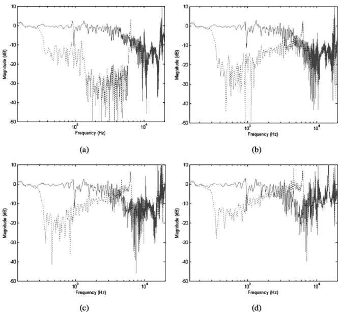
The channel separations of the left ear obtained using the 2⫻2 CCS are shown in Fig. 8 and Fig. 9 for the wide-apart and closely spaced configurations, respectively. The solid lines represent the natural separations and the dotted lines represent the separations with cross-talk cancellation. In low frequencies, due to diffraction effect, there is almost no natural separation below 400 Hz in the wide-apart configu-ration共Fig. 8兲 and below 900 Hz in the closely spaced con-figuration共Fig. 9兲. Head shadowing effect becomes visible in high frequencies, where the wide-apart configuration offers better natural separation than the closely spaced configura-tion. The peaks at higher frequencies result from the inver-sion of the notches in the ipsilateral responses. Inspection of the results indicates that the 2⫻2 CCS is not very robust. The performance degrades by 20 dB above 1.5 kHz as the head is displaced leftward by more than 5 cm irrespective of which configuration is used. Nevertheless, the closely spaced con-FIG. 10. Channel separations of the left ear obtained using the optimal closely spaced 2⫻6 configuration designed using six control points 共one at the ipsilateral ear and five at the contralateral ear兲. The solid lines represent the natural separations and the dotted lines represent the separations with cross-talk cancellation.共a兲 The channel separation with no displacement. 共b兲 The channel separation with 5-cm displacement to the left. 共c兲 The channel separation with 10-cm displacement to the left.共d兲 The channel separation with 15-cm displacement to the left.
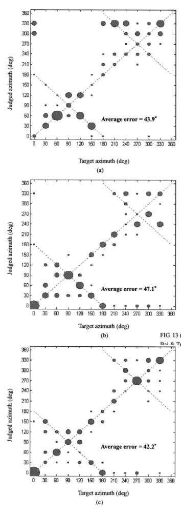
FIG. 11. Azimuth localization results of the subjective test with no head displacement.共a兲 wide-apart 2⫻2 CCS; 共b兲 closely spaced 2⫻2 CCS; 共c兲 The optimal closely spaced 2⫻6 configuration designed using six control points共one at the ipsilateral ear and five at the contralateral ear兲.
FIG. 12. Azimuth localization results of the subjective test with 5-cm head displacement to the left.共a兲 wide-apart 2⫻2 CCS; 共b兲 closely spaced 2⫻2
CCS共c兲. The optimal closely spaced 2⫻6 configuration designed using six
figuration in Fig. 9 appears to be slightly more robust than the wide-apart configuration. In Figs. 8共c兲 and 共d兲, the wide-apart CCS almost lost entire performance above 1 kHz, and the channel separations are nearly the same as the natural channel separations.
In order to improve the robustness of CCS, the optimal closely spaced 2⫻6 configuration designed using six control points共one at the ipsilateral ear and five at the contralateral ear兲 was utilized in the next experiment. Figure 10 shows the channel separations obtained using this CCS. It is evident from these plots that the robustness of the 2⫻6 CCS has been significantly improved over the previous 2⫻2 CCS. Figure 10共d兲 shows that the channel separation of the optimal CCS remains as low as ⫺30 dB above 2.5 kHz. The regu-larization parameter  is frequency dependent and con-strained by a 12-dB gain threshold. Because of thus applied regularization, some peaks in Figs. 8 –10 can be seen due to imperfect cancellation. From the observation of these results, it is fair to say that large number of loudspeakers, closely spaced configuration, and optimal control point design all contribute to the robustness of CCS against head misalign-ment.
C. Subjective listening tests
In order to compare various configurations of CCS, a subjective localization experiment was performed in the anechoic room. The test stimulus was a random noise band-limited to 20 kHz. Each stimulus was played for 5-s in du-ration and switched off for 2 s before the next stimulus was switched on. Virtual sound images at 12 directions on the horizontal plane with increment of 30° azimuth were gener-ated through the filtering of head-relgener-ated transfer functions 共HRTFs兲. The CCS configurations used in the experiment were the wide-apart 2⫻2 CCS, the closely spaced 2⫻2 CCS, and the optimal closely spaced 2⫻6 CCS. Nine human sub-jects with normal hearing participated in the experiment.
The experimental results of the judged angles versus the target angles in the localization tests are shown in Figs. 11– 13, corresponding to the cases of no misalignment, 5-cm misalignment, and 10-cm misalignment. In each case, all three CCS configurations were tests. The area of each circle is proportional to the number of the listeners who localized the same perceived angle. The 45-deg line represents the perfect localization. The average errors of localization are shown in the figures. As can be seen from the results, the optimal closely spaced 2⫻6 CCS exhibited remarkable per-formance and robustness among all configurations. The av-erage localization error using this configuration is only 32.8° 共approximately 1 increment of angle兲 for 5-cm misalign-ment.
V. CONCLUSIONS
Performance and robustness issues are examined through extensive numerical and experimental investiga-tions. An array beamforming technique using control points is exploited in the design of the CCS filters. Various configu-rations are compared in the numerical simulations. In terms of the cancellation performance, the wide-apart
configura-FIG. 13. Azimuth localization results of the subjective test with 10-cm head displacement to the left.共a兲 wide-apart 2⫻2 CCS; 共b兲 closely spaced 2⫻2
CCS.共c兲 The optimal closely spaced 2⫻6 configuration designed using six
tions could achieve higher channel separation than the closely spaced configurations. However, the closely spaced configurations appear to be more robust than the wide-apart configurations against the lateral misalignment of the head. There is a trade-off that we have to reconcile between the performance and robustness. To facilitate this trade-off, a procedure based on the Taguchi method and the GA has been developed to find optimal configurations of CCS and loud-speaker arrays that attain the best compromise between the performance 共channel separation兲 and robustness 共beam-width兲. Four configurations are compared by means of ob-jective and subob-jective experiments. The results are summa-rized in Table III.
The experimental results indicate that the optimal closely spaced 2⫻6 CCS is the best choice in terms of per-formance and robustness. It is fair to say that large number of loudspeakers, closely spaced configuration, and optimal con-trol point design all contribute to the robustness of CCS against head misalignment. Such array design is well suited to equipment that must be spatially compact, e.g., laptop computer, portable audio, mobile phone, etc. A limitation of the 2⫻6 design of loudspeaker array is that it is more com-putationally intensive than the 2⫻2 system. The 2⫻6 CCS requires 12 filters versus 4 filters in the 2⫻2 CCS. If com-putation loading is an issue, however, the closely spaced 2⫻2 CCS is perhaps the second best choice. Some limita-tions of the employed optimization methods should also be mentioned. Although the Taguohi method is well suited to problems with discrete levels, the choices must be prespeci-fied. The number of combinations becomes exceedingly large when too many factors to investigate are involved. The same situation happens to the GA; the search requires a very long time to converge for problems with long-coded chromo-somes. However, this is not a problem for the CCS in the paper since only loudspeaker spacing is the major design variable. It should be borne in mind that the configuration of the CCS suggested may not be the ultimate optimal, but is the best of the configurations considered.
The horizontally placed loudspeaker array suggested in the paper could have potential impact on the way people implement 3D sound in practical applications. For example,
conventional wide-apart stereo loudspeakers are common-place in PC multimedia and TV applications, but are not effective configurations in the context of 3D audiovisual re-production. The new loudspeaker configuration proposed in this paper provides a useful alternative.
ACKNOWLEDGMENT
The work was supported by the National Science Coun-cil in Taiwan, Republic of China, under the Project Number NSC 92-2212-E009-030.
1
B. B. Bauer, ‘‘Stereophonic earphones and binaural loudspeakers,’’ J. Au-dio Eng. Soc. 9„2…, 148–151 共1961兲.
2M. R. Schroeder and B. S. Atal, ‘‘Computer simulation of sound
transmis-sion in rooms,’’ IEEE Conv. Record. 7, 150–155共1963兲.
3
P. Damaske and V. Mellert, ‘‘A procedure for generating directionally accurate sound images in the upper- half space using two loudspeakers,’’ Acustica 22, 154 –162共1969兲.
4D. H. Cooper, ‘‘Calculator program for head-related transfer functions,’’ J.
Audio Eng. Soc. 30, 34 –38共1982兲.
5
W. G. Gardner, ‘‘Transaural 3D audio,’’ MIT Media Laboratory Tech. Report, 342,共1995兲.
6A. D. Blumlein, ‘‘Improvements in and relating to sound-transmission,
sound-recording and sound-reproducing systems,’’ J. Audio Eng. Soc.
6„2…, 91–99 共1958兲.
7D. H. Cooper and J. L. Bauck, ‘‘Prospects for transaural recording,’’ J.
Audio Eng. Soc. 37, 3–19共1989兲.
8J. L. Bauck and D. H. Cooper, ‘‘Generalized transaural stereo and
appli-cations,’’ J. Audio Eng. Soc. 44, 683–705共1996兲.
9
C. Kyriakakis, T. Holman, J. S. Lim, H. Homg, and H. Neven, ‘‘Signal processing, acoustics, and psychoacoustics for high-quality desktop au-dio,’’ J. Visual Commun. Image Represent 9, 51– 61共1997兲.
10C. Kyriakakis, ‘‘Fundamental and technological limitations of immersive
audio systems,’’ Proc. IEEE 86, 941–951共1998兲.
11D. B. Ward and G. W. Elko, ‘‘Optimal Loudspeaker Spacing for Robust
Crosstalk Cancellation,’’ Proc. ICASSP 98, IEEE, 3541–3544共1998兲.
12D. B. Ward and G. W. Elko, ‘‘Effect of loudspeaker position on the
ro-bustness of acoustic crosstalk cancellation,’’ IEEE Signal Process. Lett.
6„5…, 106–108 共1999兲.
13T. Takeuchi and P. A. Nelson, ‘‘Robustness to head misalignment of
vir-tual sound imaging systems,’’ J. Audio Eng. Soc. 109, 958 –971共2001兲.
14T. Takeuchi and P. A. Nelson, ‘‘Optimal source distribution for binaural
synthesis over loudspeakers,’’ J. Audio Eng. Soc. 112, 2786 –2797共2002兲.
15
A. Sibbald, ‘‘Transaural acoustic crosstalk cancellation,’’ Sensaura White Papers共1999兲 共http://www.sensaura.co.uk兲
16M. Tanter, J.-L. Thomas, and M. Fink, ‘‘Time reversal and the inverse
filter,’’ J. Acoust. Soc. Am. 108, 223–234共2000兲.
17
O. Kirkeby, P. A. Nelson, and H. Hamada, ‘‘Fast deconvolution of multi-channel systems using regularization,’’ IEEE Trans. Speech Audio Pro-cess. 6, 189–194共1998兲.
18H. C. Robert, Jr., Fundamental Concepts in the Design of Experiments
共Saunders College Publishing, Philadelphia, 1982兲.
19
J. H. Holland, ‘‘Outline for a logical theory of adaptive system,’’ J. ACM 3, 297–314共1962兲.
20C. T. Lin and C. S. G. Lee, Neural Fuzzy Systems共Prentice-Hall,
Engle-wood Cliffs, NJ, 1996兲.
21
T. Takeuchi, P. A. Nelson, and H. Hamada, ‘‘Robustness to head misalign-ment of virtual sound imaging systems,’’ J. Acoust. Soc. Am. 109, 958 –
971共2001兲.
22A. Schuhmacher and J. Hald, ‘‘Sound source reconstruction using inverse
boundary element calculations,’’ J. Acoust. Soc. Am. 113, 114 –127
共2003兲.
23B. S. Atal, M. Hill, and M. R. Schroeder. ‘‘Apparent sound source
trans-lator.’’ U.S. Patent No. 3236949. 22 Feb., 1966.
24W. G. Gardner, 3D Audio using Loudspeakers共Kluwer Academic,
Dor-drecht, 1998兲.
25A. V. Oppenheim and R. W. Schafer, Discrete-Time Signal Processing,
2nd ed.共Prentice-Hall, Englewood Cliffs, NJ, 1999兲. TABLE III. Comparison of the CCS configurations. Performance is the
average channel separation throughout 20 kHz. Robustness is the lateral displacement 共in 5-cm increments兲 of the head that allows for decay of channel separation within 5 dB. The numbers corresponding to the rows of performance and robustness are experimental data.
2⫻2 CCS close 2⫻2 CCS apart 2⫻6 CCS close 2⫻6 CCS apart Performance ⫺20 dB ⫺23 dB ⫺15 dB ⫺15 dB Robustness ⫾5 cm ⫾0 cm ⫾10 cm ⫾5 cm Subjective localization test
good good excellent fair
Number of CCS filters
4 filters 4 filters 12 filters 12 filters