Printed in Great Britain Pergamon Press pk
E N A M E L E D H E A T E X C H A N G E R F O R H E A T R E C O V E R Y A P P L I C A T I O N S
B. J. HUANG
Department of Mechanical Engineering, National Taiwan University, Taipei, Taiwan 10764, Republic of China
(Received 28 July 1987)
I N T R O D U C T I O N
Energy recovery from various wasted heat sources, such as the flue gases of boilers, furnaces, and combustion devices, etc. or dumped hot liquid effluent in industrial plants, has become a worldwide interest since the energy crisis. Since most of the wasted energy sources are always highly contaminated, corrosive and sometimes at high temperatures, such as in glass furnaces [1, 2], the traditional heat exchangers made from ordinary mild steels are obviously not applicable under these severe environmental conditions. Fouling and corrosion are the most serious problems in the recovery of heat.
Heat exchangers made from special alloys or non-metallic materials such as ceramics were developed in recent years to cope with this problem, however, special-alloy heat exchangers would increase the equipment cost dramatically, while the ceramic heat exchanger would suffer from the problems of low thermal conductivity, poor heat transfer efficiency and brittleness as well as high cost [3]. Recently, a glass tube heat exchanger has been successfully used for the heat recovery from the exhaust of a spray dryer at 110°C but with high solids content [4]. It was claimed that payback
period
is about 3 yr.A heat exchanger coated with polytetrafluoro-ethylene (Teflon) [5] was developed for the recovery of sensible and latent heat, however, the highest endurable temperature which can be reached to date is approximately 250°C. This is still not suitable for waste heat recovery at higher temperatures.
For applications of waste heat recovery at high temperatures, a new heat exchanger made from enameled metal was developed in the present study.
D E V E L O P M E N T O F E N A M E L E D H E A T E X C H A N G E R
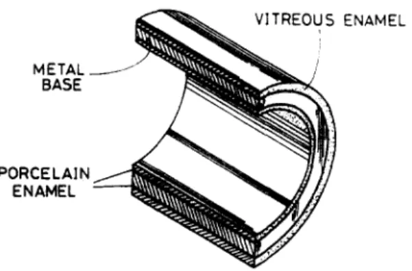
The heat exchanger developed in the present study uses a conventional metallic material, such as mild steel, as the basic metal for efficient heat transfer purposes and for providing high strength. On this base metal, a thin layer of non-metallic material made of porcelain enamel is coated to act as a protecting layer. To further improve the resistance towards alkali, acids, water vapour and various organic solvents and also towards heat, above the porcelain enamel layer a thin layer of vitreous enamel is produced to form a dual-layer heat transfer surface. See Fig. 1.
The porcelain enamel is a ceramic substance, produced by a combination of refractory, flux, opaque agents, coiour pigment, electrolyte and dispersions [6]. The chemicals are smelted together at 1200-1300°C and the molten mass is granulated and cooled in water. It is called "frit'. This granulate or frit is finely milled in ball mills together with water, clay and sodium silicate to a viscous, non-sedimenting dispersion which, by dipping or spraying, may be applied to the carefully cleaned object. The coating is first dried at a temperature o f about 125°C and then burnt at 500-850°C for 45-15 rain, depending on the nature and thickness of the foundation metal. The enamel, which is partly molten in this process, is strongly bonded to the basic metal and forms a porcelain enamel surface. The basic metal can be low-carbon mild steel, aluminium or copper alloys depending on specific applications, and for which the chemical compositions as well as the burning process (e.g. temperature and time) of the enamel may be slightly different.
204 B.J. HUANG
VITREOUS
E N A M E LMETAL
BASE
PORCELAIN
1
ENAMEL
Fig. I. Schematic of enameled heat exchanger tube.
The vitreous enamel is a glassy substance, produced by a combination of glass former, flux, stabilizers, opaque agents and colour pigments. The glass former consists mainly of silica sand and borax, and the flux of potassium and sodium oxide. Stabilizers for obtaining better chemical resistance are calcium oxide and aluminium oxide. The opaque agents usually consist of titanium dioxide and zirconium dioxide which are insoluble in the glass. The colour pigments are coloured metal oxides. The processes of producing vitreous enamel frit and forming vitreous enamel are the same as those in producing porcelain enamel except that the burning temperature and the period of time may be slightly different.
The metal base is the main heat transfer medium, which can be designed in different shapes depending on the requirement of heat transfer surface designs. For circular heat transfer tubes, the porcelain and the vitreous enamels are coated on both sides of the heat transfer surface as shown in Fig. 1. With vitroous enamel on the outside surface, which will he in contact with the hot fluid, fouling can be g r ~ t l y reduced due to its low adhesion property. This same coating technique can also be a p p l i ~ to heat transfer surfaces of different shapes (see Fig. 2) and to the supporting structure surfaces of the heat exchanger. The total thickness of the dual-layer enamel coated is around 0.15--0.2 mm. Materials such as silicone elastomer can be used for sealing between the tubes and the frame.
EXPERIMENTS 1. Thermal performance test
To demonstrate the performance of the present design, a prototype cross-flow air-to-air heat exchanger was made for testing, with the coating technique described above. The base metal or
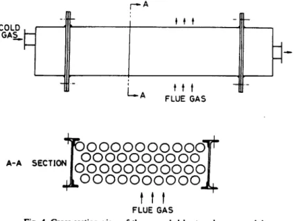
heat transfer surfaces are low-carbon steel tubes with 2.54 cm diameter, 1 m long and 1 mm thick (see Figs 3 and 4). The tube pitch is 4.45 cra and in a triangular arrangement. The heat exchanger was designed in modular type with 42 tubes in each module. Both sides of the heat transfer surface, as well as that of the supporting structure, are all coated with the dual-layer enamel.
Cold air at room temperature was allowed to pass through the tube insides, while hot air with temperature controlled in the range 30(O50°C was passing through the tube outside. The whole test equipment was as is shown in Fig. 5. The mass flowrates of both streams were adjustable during testing. It was found that the overall heat transfer coefficient U0 at various operating conditions remains approximately constant and has a mean value of 12.4 kcal h -m m -2 °C-L See Fig. 6. This is due to the fact that the radiation heat transfer in the heat exchanger dominates. Improvement on the heat transfer coefficient in both convective and radiative patterns can still be achieved by reducing the tube pitch or spacing and increasing the flow of hot stream or introducing turbulators to the inner sides of the tubes.
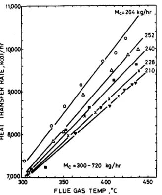
The temperature rises of the cold air through the heat exchanger were shown to increase with increasing flue gas temperature. See Figs 7 and 8. It is seen that a temperature rise of over 120°C can be obtained for flue gas temperature higher than 300°C.
SUPPORT HEAD
TUBE R
PLATE
ENAMELED TUBE
Fig. 3. Overview of enameled heat exchanger module.
r.--A
LA
ttt
FLUE GASh
A-A4~FO00000 00000"~
~
J(~uuOuuO(ou(OUI
. oooooooooo. L
tit
FLUE GAS206 B.J. HUANG ~EXHAUST COLD AIR MIXING IN AIR OIL F y I ~ BURNER i COLD AIR \,OUT ENAMELED | it .F/HEAT EXCHANGER 5 HP FLUE GAS BLOWER P E ABOOYj...p- ( FURNACE • ~ L . J
3 HP COLD GAS BLOWER
L
2,400J
I i
Fig. 5. Performance test equipment.
2. M a t e r i a l test
The vitreous and porcelain enamels are well-known surface coating materials which can provide excellent resistances towards acids, alkalis, high temperatures as well as possessing good colour and outlook and have been widely used for a long time, for example in cooking utensils. Therefore, it is a proven technique applicable to the coating of heat exchanger surfaces for use in heat exchange under severe environmental conditions. An experiment performed in the laboratory also shows that
~ E 2 0 O p: z LLI M 'J 1 5 W o rt- w z ~ I0~ < n.- < 1.1.1 I 5 t~ i,i o i i
Uo:12 4"_O5 kcol/hr m 2
O O O AO O O 0 I I 300 600 760 7-20 O Mc= 264 kg/hr A 252 • 240 x 228 • 210
FLUE GAS TEMP =300-450"C
| I l
360 420 480 540
M h , k g / h r
Me= 264 =" t r r e U.l u. u~ z ,< r e i-- i - ,< epoo m M¢ = 3 0 0 - 720 k g / h r 7.000 300 350 400
FLUE GAS TEMP ,'C
450
Fig. 7. Heat transfer rate vs fluc gas temperature.
the capability of resistance towards oxidation at high temperature for the present heat exchanger material with only single-layer porcelain enamel is far superior to ordinary mild steels or the alloy steel for fire tubes of boiler (see the oxidation rate curves for different metals shown in Fig. 9) in which the oxidation rate is represented in terms of the increase of oxidation weight of the specimen. For metals with dual-layer porcelain and vitreous enamels, the oxidation rate cannot be detected
at all over the test periods.
Besides the thermal performance test, the enameled material also passed a series of tests such as spot test, thermal shock test, anti-acid test, etc. The expected life of the enameled heat exchanger is at least 5 yr in heavy duty.
u m" 20O 9
8
10C re I[ w i,,- 0 300 M e = 2 1 0 - 2 6 4 k g / h r Mh= 300-720 kg/hr . . . . 3 5 0 1 , i • • ~ 0 0 " ' ' ' 4 5 0 1 ,FLUE GAS TEMP. ,°C
Fig. 8. Temperature riae o f cold ~ vs flue gas temperature.
1
I
]
i
MILD STEEL TUBE
/ ~ I J ;
i TEST TEMP:500"C
%d
\ ="E "OILER TU"Eul < uJ re u Z I-,- ~g EN_A L U B E - 2 3 4 HEATING PERIOD, d o y s
Fig. 9. Comparison test of oxidation o f enameled heat transfer tube with conventional one.
208 B.J. HUANO
E N G I N E E R I N G A P P L I C A T I O N
The enameled heat exchanger made for the performance test in the present study (see Fig. 3) is in modular form. Direct use of a single module in a practical application is limited by its capacity. For heat recovery with large capacity, several modules can be stacked together to form a heat recovery system (see Fig. 10). Cold air flows in the tube side which is a multi-pass type in terms of heat exchanger design; while the flue gas flows through the shell side in single cross-flow mode. The heat recovery system can be treated as an n-pass single cross-flow heat exchanger where n is the number of passes or modules used.
Since the overall heat transfer coefficient for each module, U0 has been experimentally determined and shown to be approximately constant over a wide range of hot and cold gas flowrates, the overall heat transfer rate of the heat recovery system Qt can be calculated by the following energy equations:
Q, = Mc Cp~ (tc2 - to, ) = F T (U0h) (/hi - - t c 2 ) - - ( t l a - - tel )
Qt = M c C ~ ( t,2 - to,) = M h Cph ( th, -- th2 ), (2)
where F T is the correction factor for the n-pass single cross-flow heat exchanger; A is the total heat
exchanger area which equals nAo; n is the number of modules stacked together; .do is the heat transfer area of each module; /30 is the overall heat transfer codtieient of each module; Mc and Mh are the mass flowrates of cold and hot streams, respectively; Cpc and Cph are the specific heats of the cold and hot streams, respectively; tel and ta are the inlet and outlet temperatures of cold stream; th~ and t~ are the inlet and outlet temperatures of hot stream, respectively.
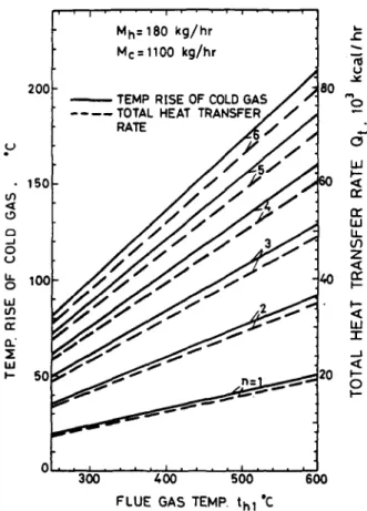
For known n, A0, tc~, Me, Mh and th,, equations (1) and (2) can be used to solve for t~, t~ and hence Qt- Some of the results are shown in Figs 11 and 12 from which thermal design calculations can be l~rformed.
To illustrate the economic feasibility of the enameled heat exchanger, a small-scale system is designed for the heat recovery of flue gas energy in a kiln or furnace. The heat recovered is used
it.2
NO.3 ~ C O ~ L D AIR "Me
NO.2 to2
Mh I thl
i
, 20¢ - 15C ,,,:x o ....J o ;' 10(; o I,,d 0." ~E Iz, J 50 I ' ' i , ' , M h = 180 k g / h r Mc = 1100 k g / h r U J ¢ ~oo-
I.~ k-- <t n." r? W I.L U') Z r? p- W -r ._.l <t l--m 0 I'-- 0 300 4 0 0 500 600 F L U E GAS TEMP. t h l 'CFig. 11. Performance curves of the heat recovery system for M b ,= l l S 0 k g h - ' .
c.J o r~ . . J o b. o w t~ 0.,' I w 10 8
%
) 0 ' - c~ L d n-. n- ~0 z ~c n- 1.- t~ -r ZO .a p - 0 300 400 500 600FLUE GAS TEMP. *C
210 B.J. HUANG
to preheat the combustion air. If four modules are used and the flue gas temperature is 600~C with 1180 kg h -z flowrate, then from Fig. 11 the combustion air (with 1100 kg h -~ flowrate) can be preheated to about 190°C and the flue gas temperature can be dropped to 430°C. The total rate of heat covered is 60,000 kcal h- m. Assuming that the furnace operates 420 h per month and the fuel cost is at 0.8 NT dollars per 1000 kcal (1 US dollar = 31 NT dollar), the cost of energy recovered or saved is
S = 60,000 x (1 - 0.05) x 420 x (0.8/1000) = 19,000 NT dollar per month,
where 5% heat loss is also assumed. The investment cost of the heat recovery system is about 240,000 NT dollars in total which includes
1. heat exchanger (4 modules, 25,000 NT dollars for each) 100,000
2. piping and insulation 50,000
3. labour and indirect cost 90,000
total 240,000.
The payback of the investment for this heat recovery system is seen to be about 1 yr. The system cost will be reduced if the system is of large size. Nevertheless, the above economic analysis shows that the enameled heat exchanger is really applicable, both technically and economically.
C O N C L U S I O N S
The present paper presents the results of the development of a new device for the use of heat exchange under severe environmental conditions. The heat transfer surface of the heat exchanger is composed of a metallic material, which acts as the main heat transfer medium, and a thin film of vitreous and porcelain enamel, which is coated on both sides of the metallic material to act as the protecting mean from environmental attacks. The high strength and high corrosion resistance of the enamel surface at high temperatures make this new device extremely attractive, not only in its low cost but also in its high quality of performance. This has been verified by the tests of thermal performance and material properties which were carried out on a prototype in the present study. The economic analysis of a system designed for the heat recovery of the flue gas energy in a furnace or kiln has shown that the payback period of the heat exchanger is around one year.
Acknowledgement--The author is very grateful to Professor S. K. Wu at the Department of Material Engineering, National
Taiwan University, for his kind help in the material test made during this study. R E F E R E N C E S
1. A. K. Kulkarni, Y. J. Wang and R. L. Webb, Fouling and corrosion in glass furnace regenerators, J. Heat Recovery
Systems 4, 87-92 (1984).
2. R. L. Webb, D. Marchiori, R. E. Durbin, Y. J. Wang and A. K. Kulkarni, Heat exchangers for secondary heat recovery from glass plants. J. Heat Recovery Systems 4, 77-85 (1984).
3. R. Nicholson, Recuperative and regenerative techniques at high temperature, J. Heat Recovery Systems 3, 385-404 (1983).
4. Energy Technology Support Unit, AERE Harwell, Heat recovery from a spray dryer using a glass tube heat exchanger,
J. Heat Recovery Systems 6, 25-31 (1986).
5. L. F. Paschke, Condensing heat exdumgers save heat, Chem. Enfng Prog. (July), 70-74, (1984). 6. K. Shaw, Technology of Enamels. M~_¢!a_ren, Stroiizdat, Moscow (1965).