階層式交換器光纖網路中的通道設置及保護
48
0
0
全文
(2) 階層式交換器光纖網路中的通道設置及保護 Tunnel Allocation and Protection in Hierarchical Cross-connect WDM Networks. 研 究 生:羅澤羽. Student:Tse-Yu Lo. 指導教授:陳. Advisor:Chien Chen. 健. 國 立 交 通 大 學 資 訊 科 學 系 碩 士 論 文. A Thesis Submitted to Department of Computer and Information Science College of Electrical Engineering and Computer Science National Chiao Tung University in partial Fulfillment of the Requirements for the Degree of Master in Computer and Information Science June 2004 Hsinchu, Taiwan, Republic of China. 中華民國九十三年六月.
(3) 階層式交換器光纖網路中的通道設置及保護. 研究生:羅澤羽. 指導教授:陳健博士. 國立交通大學資訊科學系. 中文摘要. 多單位光學交換器(Multi-granularity Optical Cross-Connect)架構是為了提供 一個有效節省成本的方式來供應越來越大的網路資料流量的需求。在多單位交換 器光纖網路中,數個綁成一束的連續波長形成一個通道(tunnel)並且像一個單獨 波長一樣一起做交換。通道路徑上的交換器尺寸可因此而變小並降低成本。這本 論文主要在探討多單位光學交換器上的通道配置及保護這兩個問題。 最近提出的容量平衡通道配置法(Capacity-Balanced Static Tunnel Allocation) 是用來解決通道配置問題。容量平衡通道配置法選擇流量進出最大的兩個節點並 在這兩點之間配置一條通道。然而當為每一個通道選擇一對節點時,容量平衡通 道配置法並沒有考慮通道長度的限制。因此,我們提出等長權重通道配置法 (Constant Length Weighted Tunnel Allocation,)來改善容量平衡通道配置法的問 題。在等長權重通道配置法中,只有符合長度限制的兩節點,才會試著在之間建 立通道。我們藉由模擬來驗證等長權重通道配置法的效能並與容量平衡通道配置 法做出較。結果顯示等長權重通道配置法的效能比容量平衡通道配置法更好。 在多單位交換器光纖網路的保護方面,我們探討單一線路故障時的保護機 制。多單位交換器光纖網路在保護機制方面還未被廣泛研究,因此這篇論文提供 i.
(4) 一個有效解決單一線路故障發生時的保護機制。我們提出通道式分段保護機制 (Tunnel-based Segment Protection)來回復因線路故障所中斷的通訊,在通道式分 段保護機制中,配置通道時同時也會考慮保護需求,當我們在網路上配置一個主 要通道時,同時也配置一個相對應的備用通道。模擬結果顯示通道式保護機制對 多單位交換器光纖網路中的單一線路故障提供一個有效的解決方法。. 關鍵字:多單位光學交換器、通道、容量平衡通道配置法、等長權重通道配置法、 通道式分段保護機制。. ii.
(5) Tunnel Allocation and Protection in Hierarchical Cross-connect WDM Networks Student: Tse-Yu Lo. Advisor: Dr. Chien Chen. Department of Computer and Information Science National Chiao Tung University Hsinchu, Taiwan, 300, Republic of China Abstract Multi-granularity Optical Cross-Connect (MG-OXC) has been proposed to provide a cost efficient way to support the increasing number of traffic requests. In the MG-OXC networks, consecutive wavelengths are bundled to form a tunnel and switched as a single unit. Networks resources, including switching fabrics and multiplexers, at the mediate nodes on the route of a tunnel thus can be reduced. This thesis considers the static tunnel allocation problem and the protection problem in MG-OXC networks. For the tunnel allocation problem, a heuristic Capacity-Balanced Static Tunnel Allocation (CB-STA) [1] has been proposed. CB-STA always tries to allocate a tunnel from the node with maximal predicted traffic going out to the node with maximal predicted traffic coming in. However, the length constraint is not considered when selecting node pairs. We propose a heuristic, Constant Length Weighted Tunnel Allocation (CLWTA), to overcome this problem of CB-STA. Only node pairs whose hop distance complies with the length constraint are tried to be allocated tunnels in CLWTA. We examine the performance of the proposed schemes, CLWTA, and make a comparison with CB-STA. The results show that CLWTA outperforms CB-STA in all switching type combinations. iii.
(6) For the protection problem, we investigate the protection schemes for the single-link failure in the MG-OXC networks. Since the protection problem has not been studied intensively in MG-OXC networks, this work aims to provide an efficient protection solution. A segment-based protection scheme, called Tunnel-based Segment Protection (TSP) that considers the tunnel allocation with protection requirement in mind is proposed to recover the communications interrupted by a fiber cut. In TSP, a corresponding link-disjoint protection tunnel is always allocated simultaneously with a working tunnel. Simulation results show that TSP provides an efficient protection solution for MG-OXC networks.. Keywords: Multi-granularity Optical Cross-Connect, tunnel, Capacity-Balanced Static Tunnel Allocation, Constant Length Weighted Tunnel Allocation, Tunnel-based Segment Protection. iv.
(7) 誌謝. 這篇論文的完成,首先要感謝我的指導老師,陳健博士。兩年來, 老師對我的勉勵與指導,讓我在遇到挫折時得以堅持下去,遇到困難 時得以順利解決問題。亦師亦友的師生關係,戰戰競競卻也充實而受 益良多。同時也感謝我的論文口試委員,林盈達教授、王國禎教授、 陳志成教授、以及李詩偉博士。他們的專業意見使得這篇論文更完整 及有意義。 感謝吳奕緯學長、林俊源、許嘉仁兩年來的鼓勵。有這些好同學 的陪伴,這兩年過得十分愉快。感謝陳盈羽、葉筱筠的相互討論,讓 我的研究更完善。 感謝家人對我毫無保留的關懷及付出,願與你們分享我的一切。 終於到了可以寫誌謝的這一天了,感謝所有曾經幫助過我的每一個 人,有了你們,我才能繼續向前走下去。. v.
(8) Table of Contents Abstract (In Chinese)....................................................................................................i Abstract........................................................................................................................iii Acknowledgement (In Chinese)..................................................................................v Table of Contents.........................................................................................................vi List of Figures.............................................................................................................vii 1. Introduction..............................................................................................................1 1.1 Multi-Granularity OXC (MG-OXC)................................................................1 1.2 Motivation and Thesis Outline.........................................................................4 2. An Effect Scheme for Fixed-Length Tunnel Allocation in Hierarchical Cross-connect WDM Networks...............................................................................7 2.1 Introduction......................................................................................................7 2.2 Background and Related Works.......................................................................8 2.3 Basic Assumption and Problem Statement.......................................................9 2.4 Heuristics for Tunnel Allocation...............................................................10 2.5 Numerical Results..........................................................................................15 3. Tunnel-based Protection Schemes in Hierarchical Cross-connect WDM Networks.................................................................................................................21 3.1 Introduction....................................................................................................21 3.2 Background and Segment Protection Schemes..............................................22 3.3 Protection Schemes on MG-OXC Networks.........................................24 3.4 Numerical Results..........................................................................................30 4. Conclusion...............................................................................................................35. vi.
(9) List of Figures Figure 1: Architecture of an MG-OXC..........................................................................2 Figure 2: (a) Traditional OXC without hierarchy...........................................................3 Figure 2: (b) MG-OXC..................................................................................................3 Figure 3: MG-OXCs with two switching tier, wavelength-switching and waveband-switching.......................................................................................4 Figure 4: A network which has a tunnel with a lightpath traversing it...........................9 Figure 5: Example of tunnel allocation........................................................................10 Figure 6: An example of auxiliary graph......................................................................12 Figure 7: An example of deriving the W-NLS for each link in the network................13 Figure 8: The 16-node network for simulation of tunnel allocation............................15 Figure 9: Number of allocated tunnels except makeup process between CLWTA and CB-STA (1F2B2L).......................................................................................16 Figure 10: Comparison of blocking probability vs. requests for CLWTA and CB-STA on the 16-node topology.............................................................................18 Figure 11: Comparison of blocking probability vs. requests for CLWTA and PC-CLWTA on the 16-node topology...........................................20 Figure 12: (a) Two working paths can share the same wavelength in link C-B...........23 Figure 12: (b) Two working paths that have common link can not share the same protection resources..............................................................................23 Figure 13: Example of path protection with MG-OXC...........................................…25 Figure 14: (a) Two tunnels, A-E and B-F in logical topology……......………………26 Figure 14: (b) Physical route of the two tunnels………………..................…………26 Figure 15: (a) Division of the working path according to the switching type………..27 Figure 15: (b) Finding a protection path for each working segment in each switching layer………………..…………………………………………………27 Figure 16: The 16-node topology for simulation of protection………………........…31 Figure 17: Simulation results of TSP and path protection with different number of lightpath requests…………………………………………………………32 Figure 18: MG-OXC only reconfigures the fiber-switching box to switch the traffic in working tunnel to protection tunnel……………...………………………33 Figure 19: Traffic load vs. blocking probability in different switching combinations in TSP.............................................................................................................34. vii.
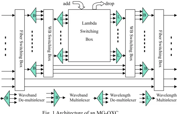
(10) Chapter 1 Introduction Wavelength-division-multiplexing (WDM) networks have emerged as a method of providing Terabits-per-second capacity for ever-increasing bandwidth demands. When increases in number of wavelength channels and fibers between node pairs may increase available capacity, the resultant managing complexity and size of optical cross-connects (OXCs) also increase. An effective way of handling this problem is to bundle a group of consecutive wavelength channels together and switch them as a single unit on a specific route to reduce the required resources of intermediate cross-connects along the route. The tunnel-like passage created by the bundled wavelength channels is defined as a waveband/fiber tunnel. The wavelengths in a tunnel must be switched together except at the two ends of the tunnel. The node that support such multi-granularity switching, e.g. wavelength, waveband, and fiber, is termed hierarchical cross-connect or multi-granularity optical cross-connect (MG-OXC). This thesis examines the tunnel allocation and protection problems related to the networks that using the node architecture, MG-OXC.. 1.1 Multi-Granularity OXC (MG-OXC) Networks The network considered in this thesis is composed of the MG-OXC architecture proposed in [1], shown in Fig. 1. A MG-OXC mainly comprises fiber-, waveband-, and wavelength-switching boxes. The fiber- and waveband-switching boxes on the left-hand side serve as selectors on the input fibers and wavebands while the fiberand waveband-switching boxes on the right-hand side serve as OXCs that switch fibers and wavebands.. 1.
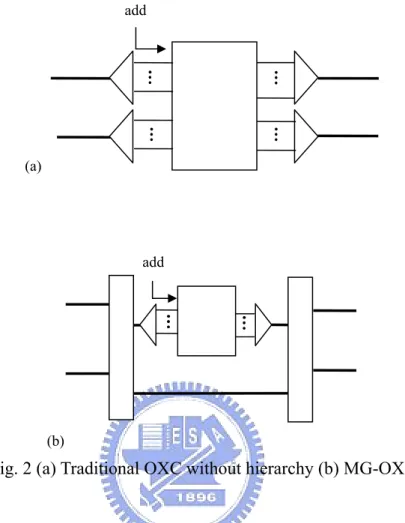
(11) add B. B. L. L. Lambda Box. L. L. B. B. Waveband De-multiplexer. B. Waveband Multiplexer. L. Wavelength De-multiplexer. L. Fiber Switching Box. Switching. WB Switching Box. WB Switching Box. Fiber Switching Box B. drop. Wavelength Multiplexer. Fig. 1 Architecture of an MG-OXC For the same number of input fibers and output fibers, a MG-OXC costs much less than the traditional OXC. Fig. 2 gives an example. Assume that there are ten wavelengths in a fiber and a node has two fibers coming in and going out. In Fig. 2, assume that there are ten wavelengths in a fiber, and only calculates the ports needed for each switch at the left side. In Fig. 2(a), the traditional OXC uses a 20×20 wavelength switch. However, in Fig. 2(b), the MG-OXC uses a 10×10 wavelength switch and two 4×4 fiber switches. Although cost savings can be achieved by using MG-OXCs, this characteristic reduces the throughput and the performance of the networks. For example, in Fig. 2(b), the traffic in the fiber can be accessed by de-multiplexing only one of the two fibers into wavelengths. The traffic in the other fiber must bypass this node since no redundant wavelength-switching ports left for the wavelengths in this fiber.. 2.
(12) add. (a). add. (b). Fig. 2 (a) Traditional OXC without hierarchy (b) MG-OXC. In MG-OXC networks, a directional link consists of F fibers in which F1, F2, and. F3. fibers. are. assigned. as. fiber-switched,. waveband-switched,. and. wavelength-switched fibers respectively (i.e. F = F1 + F2 + F3). On each end of a tunnel, wavelength-switching ports are required so that the traffic can be grouped or de-grouped. For example, in Fig. 3, there is a tunnel between node A and node C. A lightpath from node A to node C can be established by traversing that tunnel. Note that the number of wavelength-switching ports the tunnel consumes at the two ends of the tunnel is equal to the number of the wavelengths that the tunnel carries.. 3.
(13) Ports consumed by the fiber tunnel. Lambda Switching box. Ports consumed by the fiber tunnel. Lambda Switching box. Lambda Switching box. Fig. 3 MG-OXCs with two switching tier, wavelength-switching and waveband-switching 1.2 Tunnel Allocation and Protection Problems Although applying MG-OXC can reduce network costs, some problems also arise. The bundled channels in MG-OXC networks form the so-called waveband or fiber tunnels, in which lightpaths can not be wavelength-switched except at the ends of the tunnels. Tunnels complicate the routing and wavelength assignment (RWA) problem and should be allocated carefully to achieve higher network performance. Additionally, the protection problem in MG-OXC networks should also be examined, since it has not been intensively studied. This work investigates problems related to MG-OXC networks, including the tunnel allocation problem and the protection problem. The remainder of this thesis is organized as follows. Chapter 2 deals with where to allocate tunnels on the network to maximize network performance. We consider the following network design problem. Given fixed amount of network resources and a historical traffic matrix that the dynamic requests will follow, the objective is to determine a set of tunnels that minimize the blocking probability for the dynamic traffic requests. To solve the above problem, the. 4.
(14) heuristic Capacity-Balanced Static Tunnel Allocation (CB-STA) [1] has been proposed that first estimates the amount of traffic traveling through each node by routing the historical traffic matrix on the network. Then the nodes with maximal traffic going out and maximal traffic coming in are selected repeatedly for tunnel allocation. To efficiently utilize the wavelength ports and fibers, each node pair selected for tunnel allocation is required to follow a tunnel length constraint, i.e., each tunnel should be equal to an average hop distance. Since CB-STA does not consider the tunnel length constraint when picking the node pairs, only few of the selected pairs for tunnel allocation comply with the length constraint. We propose the heuristic, Constant Length Weighted Tunnel Allocation (CLWTA) scheme that aims to improve CB-STA. Instead of finding node pairs for the tunnel allocation without considering the tunnel length constraint, CLWTA only takes node pairs whose hop distance complies with the length constraint into consideration. Only those node pairs possess the potential to be allocated tunnels. Chapter 3 investigates the problem of single-link failure protection in the multi-fiber network with MG-OXC. We are given fixed amount of network resources and a historical traffic matrix. The objective is to minimize the blocking probability under the constraint that for each request, a working path and protection path must be found simultaneously to guarantee 100% survivability. Since the protection problem has not been intensively studied in the MG-OXC networks, the mass MG-OXC deployment is at the risk of huge data losses once a link failure occurs. This work thus aims to provide an efficient protection scheme for MG-OXC networks. The protection problem in MG-OXC networks can be divided into two phases, tunnel allocation and finding link-disjoint lightpaths for each incoming request. To provide protection for lightpath requests, an intuitive solution is to allocate tunnels without protection consideration and then find two link-disjoint lightpaths from 5.
(15) source to destination for each incoming request. Although the intuitive heuristic provides a protection solution for the MG-OXC networks, it does not consider the protection while allocates tunnels. The lack of protection consideration while allocating tunnels complicates the finding of link-disjoint lightpaths since two different tunnels may actually traverse the same physical link. Thus, we have pay additional attention to the overlapping of tunnels when finding link-disjoint path pair. Therefore, we propose the protection scheme named Tunnel Based Segment Protection (TSP) that considers the tunnel allocation with protection requirement in mind. In TSP, a protection tunnel is always allocated simultaneously with a working tunnel. The channels dedicated for protection can be shared more easily. In addition, performance of the network is improved since working and protection tunnels use the same wavelength-switching ports in MG-OXC networks in which port resources are rare. Chap 4 concludes the results of our works and suggests some possible future works.. 6.
(16) Chapter 2 An Effect Scheme for Fixed-Length Tunnel Allocation in Hierarchical Cross-connect WDM Networks 2.1. Introduction This chapter considers tunnel allocation problem in the hierarchical. wavelength-division-multiplexing (WDM) optical networks with varying traffic granularity among wavelengths, wavebands, and fibers. Given fixed amount of network resources and a historical traffic matrix that the dynamic requests will follow, the objective is to determine a set of tunnels that minimize the blocking probability for the dynamic traffic requests. Capacity-Balanced Static Tunnel Allocation (CB-STA) has been proposed but has some problems when selecting node pairs for tunnel allocation. We propose a heuristic algorithm, the Constant Length Weighted Tunnel Allocation (CLWTA), which is based on an auxiliary graph used to rate the preference of tunnel allocation for each node pair to improve CB-STA. Additionally, the Port-Constraint Constant Length Weighted Tunnel Allocation (PC-CLWTA) which considers the constraint of wavelength-switching ports is proposed. Simulation is conducted to compare the performance of CB-STA, CLWTA and PC-CLWTA. The remainder of this chapter is organized as follows. Section 2.2 introduces the background and related work. Section 2.3 then illustrates the basic concepts related to the problem and assumptions made in this chapter. Heuristics for tunnel allocation including CB-STA, CLWTA and PC-CLWTA are presented in Section 2.4. Finally, simulation results are given in Section 2.5.. 7.
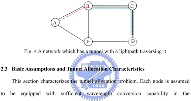
(17) 2.2 Background and Related Works This section focuses on the related works that consider multi-granularity traffic. More flexible and cost-efficient allocation of capacity is required to satisfy the growing demand for bandwidth. A considered method that has been studied intensively is to bundle a group of consecutive wavelength channels together and switch them as a single unit on a specific route to reduce the required resources of intermediate cross-connects along the route [1-6]. In [2], merits of hierarchical or multi-granularity OXC (MG-OXC) were summarized such as small-scale modularity, reduced cross-talk, and the reduced of complexity. [3] showed that the number of ports required when grouping of consecutive lightpaths are applied to the network (excluding grouping the traffic from different source nodes to different destination nodes) can be significantly reduced, compared to a traditional OXC solution. In [4], which employs a two-stage scheme of waveband and wavelength, an integer linear programming (ILP) formulation and a heuristic are given that aim to group lightpaths with the same destination only, while in [5] both the ILP and heuristic were given to handle the more general case. While [3]-[5] discussed aim to dimension the network resources given the set of lightpath requests to be established, in [1] a novel switching architecture, MG-OXC was proposed to minimize the blocking probability for the dynamic requests given the limited network resources. In [1], the tunnel-like passage created by the bundled wavelength channels was defined as a waveband/fiber tunnel. If any residual capacity is left in the tunnel, it can be used to accommodate future lightpath requests. On the other hand, when no lightpath is traversing the tunnel, it can be torn down to release the resources including the link and the wavelength-switching ports as well as the multiplexer and de-multiplexer along the tunnel path for the future use. To illustrate this, the network in Fig. 4 is considered. Each link is assumed to have ten wavelengths, 8.
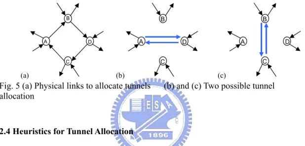
(18) λ1 to λ10, and can be divided into two wavebands with λ1 to λ5 being waveband 1 and λ6 to λ10 being waveband 2. Assume that a tunnel set up already exists from B to D on waveband 1 which is traversed by a lightpath from A to D on λ1. If the next lightpath request is from B to D, the established tunnel can be utilized to reach D. On the other hand, if the original lightpath is dropped, the tunnel can be torn down and the resources dedicated for this tunnel can be released for future use.. B. C. E. D. A. Fig. 4 A network which has a tunnel with a lightpath traversing it 2.3 Basic Assumptions and Tunnel Allocation Characteristics This section characterizes the tunnel allocation problem. Each node is assumed to be equipped with sufficient wavelength conversion capability in the wavelength-switching layer. Therefore, a lightpath in the wavelength-switching layer can be converted into any other wavelength if necessary. The tunnels are restricted to traverse only on their shortest paths from their ingress to egress node thus increasing the efficiency network resource consumption. The tunnels are restricted to traverse only on their shortest paths from their ingress to egress node thus increasing the efficiency network resource consumption. A tunnel can be allocated between a node pair, if there is free capacity on each link along its route. Note that for the waveband tunnel, it has to use the same waveband on each link along the route. To bring up an allocated tunnel, wavelength-switching ports are further required at the two ends of the tunnel. Fig. 5 illustrates an example of two possible tunnel allocations if the length of 9.
(19) tunnels is restricted to two. Fig. 5(a) is part of the physical network. Four fibers are used for tunnel allocation, including AB , BD , DC and CA . Fig. 5(b) and (c) show the two possible ways of tunnel allocation. The total traffic trend should be considered when deciding which tunnel set is suitable. For example, if most traffic is between node A and node D, the tunnel set in Fig. 5(b) is more suitable. If most traffic is between node B and node C, the tunnels are allocated in Fig. 5(c).. B. A. B A. D. A. D. (b). D C. C. C. (a). B. (c). Fig. 5 (a) Physical links to allocate tunnels allocation. (b) and (c) Two possible tunnel. 2.4 Heuristics for Tunnel Allocation We first briefly introduce Capacity-Balanced Static Tunnel Allocation (CB-STA) proposed in [1]. Then we present our heuristic Constant Length Weighted Tunnel Allocation (CLWTA) that aims to improve CB-STA.. Capacity-Balanced Static Tunnel Allocation (CB-STA) CB-STA aims to allocate tunnels off-line before start serving the lightpath requests. The process comprises three stages: (a) tunnel ingress-egress (I-E) pair selection, (b) tunnel allocation and (c) makeup process. In (a), a series of I-E pairs are selected sequentially for the tunnel allocation stage in (b). To select I-E pairs, CB-STA estimates the amount of traffic traveling through each node by routing a historical traffic matrix in the network. Then the nodes with maximal traffic going out and maximal traffic coming in are selected repeatedly for tunnel allocation. In (b), 10.
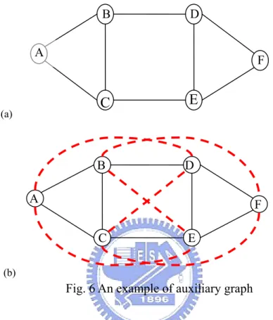
(20) CB-STA tries to allocate a tunnel for each I-E pair selected in (a). After (a) and (b), the makeup process (c) is performed to further utilize the remaining resources to fill the fiber- and waveband-switching layer with as many tunnels as possible. The tunnel allocated at stage (b) is required to follow a tunnel length constraint which is set to the minimum integer that is larger than the average physical hop distance between each node pair in the network. This is because when the tunnel length is too small, although the short tunnels are flexible and easily utilized by most of the lightpaths, the wavelength-switching ports are used up easily since the wavelength-switching ports are required at the ingress and egress nodes of each tunnel. When the tunnel length is too large, although wavelength-switching ports can be greatly saved, the tunnels may not be suitable for the requests since most of the lightpath requests are shorter than the tunnels. We observe that the I-E pairs selected in stage (a) of CB-STA does not consider the tunnel length constraint, therefore most of the tunnels are allocated at the stage (c), leaving the performance of CB-STA some space to be improved.. Constant Length Weighted Tunnel Allocation (CLWTA) CLWTA is proposed to overcome the problem in CB-STA. CLWTA allocate tunnels off-line and is based on an auxiliary used to rate the preference of tunnel allocation for each node pair. The process comprises four stages: (a) construction of auxiliary graph, (b) weight calculation for edges in the auxiliary graph, (c) weighted auxiliary graph based tunnel allocation, and (d) makeup process. Let G(V, Ep) be the original topology. (a) construction of auxiliary graph. where V denotes the set of nodes and Ep represents the set of all physical links connecting the nodes. The auxiliary graph G’(V, E’) is constructed by adding auxiliary links El between the node pairs that have their shortest physical hop length 11.
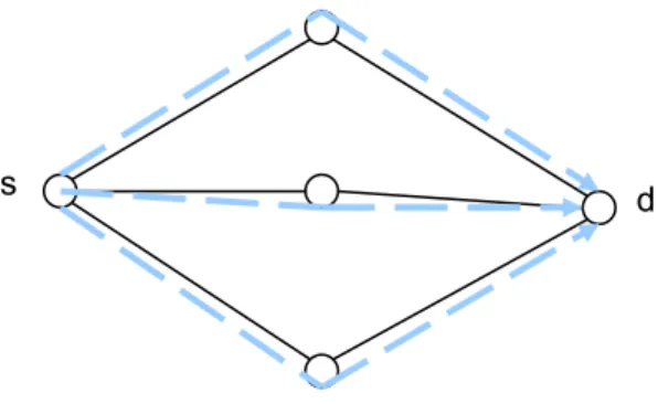
(21) follow the length constraint (i.e., E’ = Ep + El). The auxiliary links represent the potential tunnels that could be allocated on the network.. D. B A. F. E. C. (a). B. D. A. F C. E. (b). Fig. 6 An example of auxiliary graph Fig. 6 gives an example of construction of auxiliary graph where Fig. 6(a) is the original topology with the average hop distance equal to two and Fig. 6(b) is the corresponding auxiliary graph, in which dashed links represent the auxiliary links. (b) weight calculation for edges in the auxiliary graph. The. Weighted. Network Link State (W-NLS) [1] is applied to determine the weight of each auxiliary link in the auxiliary graph. The weight of an auxiliary link is the predicted loads for the two nodes at the ends of that link. The larger the weight of an auxiliary link, the higher priority the node pair for that link gains to be allocated tunnels.. 12.
(22) s. d. Fig. 7 An example of deriving the W-NLS for each link in the network. Fig. 7 gives an example of how the weights are derived. There are three shortest paths from node s to d. The load from s to d is assumed to be equally distributed on the three paths. The weight of each link traversed by the shortest paths is thus increased by one third of the load from s to d. The weight of all the auxiliary links can be derived by applying the above procedure for all the node pairs in the network. (c) weighted auxiliary graph based tunnel allocation. This stage applies a. greedy approach to allocate a set of tunnels according to the weight derived in the previous stage. The auxiliary link in G’ with the maximum weight is first selected, and an attempt is made to allocate a fiber tunnel for this auxiliary link. If the fiber tunnel can be allocated successfully, the weight of the corresponding auxiliary link is decreased by δ F =. ∑W. i, j. L ⋅ FT D. , where Wi,j is the weight of the auxiliary link connecting. node i and j, L the number of directional links in the original network topology, FT the number of fibers dedicated for tunnel allocation in each directional link and D the length constraint. Otherwise, we try to allocate a waveband tunnel for this auxiliary link. If a waveband tunnel can be successfully allocated, the weight of this auxiliary link is decreased by δ B =. ∑W. i, j. L ⋅ B ⋅ FT D. , where B is the number of wavebands in a fiber.. If both fiber and waveband tunnels fail to be allocated, the weight of this auxiliary 13.
(23) link is set to 0. The above procedure is repeated until all of the weights of the auxiliary links in G’ are equal to or less than 0. (d) makeup process. This process is used to further utilize the remaining. resource after stage (c). The tunnels allocated in this stage do not have to follow the length constraint. The whole algorithm of CLWTA is summarized as follows.. Constant Length Weighted Tunnel Allocation (CLWTA) Step1. Form the auxiliary graph by adding all possible tunnels to the Step2. Step3. Step4.. Step5.. physical network. Compute weight for each possible tunnel by routing the traffic matrix on the auxiliary graph Stop if the weight for each auxiliary link is smaller or equal to 0. Try to allocate fiber tunnel for the auxiliary link with maximum weight. If successful, decrease the weight of this auxiliary link by δF and go to Step 3. Otherwise, go to Step 5. Try to allocate waveband tunnel for this auxiliary link. Decrease the weight of this auxiliary link by δB. Go to Step 3.. In CLWTA and CB-STA, a tunnel can be allocated if free link capacity on the route between the ingress and egress of the tunnel is available. An allocated tunnel needs to be further brought up to be utilized by lightpaths. When a tunnel is brought up, wavelength-switching ports are needed so that wavelengths can be group or de-group at two ends of the tunnel. The number of wavelength-switching ports consumed at each end of the tunnel so that the tunnel can be brought up is equal to the capacity (in wavelength) of that tunnel. We also propose another heuristic, Port Constraint- Constant Length Weighted Tunnel Allocation (PC-CLWTA) with slight modification on CLWTA. In PC-CLWTA, 14.
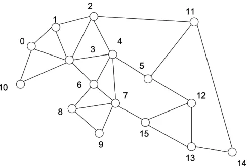
(24) after a tunnel is allocated, wavelength-switching ports at the ingress and egress nodes of the tunnel are dedicated to the tunnel. That is, a tunnel can not be allocated if any on the two ends of the tunnel has insufficient wavelength-switching ports. PC-CLWTA improves the performance when the wavelength-switching ports is significantly fewer than the resources in the fiber-switching and waveband-switching layers. The performances of schemes described above are evaluated in the following section. 2.5 Numerical Results The topology we use is a 16-node network show in Fig. 8. We assume that each directional link has five fibers. Each fiber contains forty wavelengths which are divided into four wavebands with wavelength 1 to 10 in the first waveband, 11 to 20 the second, …, and 31 to 40 the forth. The traffic is uniformly distributed on all node pairs and each request is for a lightpath. The inter-arrival time between two requests is determined by an poisson distribution function with rate ρ, and the request holds the resources it traverses for a time period determined by an exponential distribution function with rate 1. Let (F1)F(F2)B(F3)L stand for the experiment with F1 fibers for fiber-switching, F2 fibers for waveband-switching, and F3 fibers for wavelength-switching for each directional link. The following three combinations of switching type are examined: 1F1B3L, 1F2B2L and 2F2B1L. 15.
(25) 2. 11. 1 0. 4. 3. 5 6. 10. 7. 12. 8 15 9 13. 14. Fig. 8 The 16-node network for this simulation. 200. 150 CB-STA 100. WTA Ideal. 50. 0 Fiber Tunnel. Waveband Tunnel. Fig. 9 Number of allocated tunnels except makeup process among CLWTA, CB-STA and the ideal number (1F2B2L) Fig. 9 compares the number of allocated tunnels when CB-STA and CLWTA are used without performing their makeup process. The maximum number of allocated fiber tunnels and waveband tunnels are. E p × F1 D. and. E p × F2 × B D. respectively, where. |Ep| is the number of directional links on the topology. The number of allocated fiber/waveband tunnels without makeup process in CB-STA is considerably smaller 16.
(26) than the maximum number. The reason is that most of the I-E pairs selected in CB-STA do not follow the tunnel length constraint.. 2F2B1L. Blocking Prob.. 0.2 0.15. CB-STA relaxed CB-STA WTA. 0.1 0.05 0 450. 500. 550. 600. 650. 1300. 1400. Load. (a). 1F2B2L 0.15. CB-STA relaxed CB-STA. Blocking prob.. WTA 0.1. 0.05. 0 1000. 1100. 1200 Load. (b). 17.
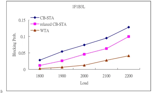
(27) 1F1B3L 0.15. CB-STA relaxed CB-STA. Blocking Prob.. WTA 0.1. 0.05. 0 1800. 1900. 2000. 2100. 2200. Load. (c). Fig. 10Comparison of blocking probability vs. requests for CLWTA and CB-STA on the 16-node topology Fig. 10compares different blocking probability of the CLWTA and CB-STA under different load ρ. The relaxed CB-STA relaxes the length constraint D in CB-STA. More specifically, in relaxed CB-STA, tunnels with lengths between D-1 and D+1 are permitted to be allocated. Therefore, more useful tunnels can be allocated in relaxed CB-STA than in CB-STA. The results show that CLWTA has the lowest blocking probability in all switching type combinations. The reason is that CLWTA takes the length constraint into account when allocating tunnels while in CB-STA and relaxed CB-STA, length constraint is not carefully considered in their I-E pair selection stage.. 18.
(28) 2F2B1L. Blocking prob.. 0.15. WTA PC-WTA. 0.1. 0.05. 0 500. 550. 600. 650. 700. Load. (a). 1F2B2L. Blocking prob.. 0.15. WTA PC-WTA. 0.1. 0.05. 0 1300. 1400. 1500 Load. (b). 19. 1600. 1700.
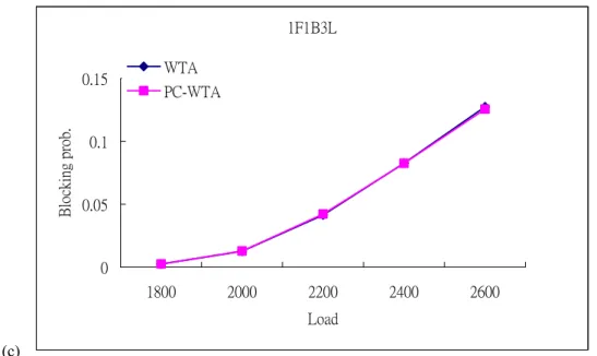
(29) 1F1B3L. Blocking prob.. 0.15. WTA PC-WTA. 0.1. 0.05. 0 1800. 2000. 2200. 2400. 2600. Load. (c). Fig. 11 Comparison of blocking probability vs. requests for CLWTA and PC-CLWTA on the 16-node topology PC-CLWTA outperforms CLWTA when each node in the MG-OXC network has only limited wavelength-switching ports (in Fig. 11(a)). That is because tunnels in PC-CLWTA. are. only. allocated. between. nodes. that. have. sufficient. wavelength-switching ports. The link capacity and wavelength-switching ports are more efficiently utilized since most of them are consumed by the auxiliary links with higher weights. However, when there are sufficient wavelength-switching ports, performance of PC-CLWTA is the same as CLWTA (i.e., performance curves of the two algorithms in Fig.11 (b) and (c) overlaps).. 20.
(30) Chapter 3 Tunnel-based Protection Schemes in Hierarchical Cross-connect WDM Networks 3.1 Introduction In this Chapter, we investigate the protection schemes for single-link failure in hierarchical cross-connect WDM networks. Multi-granularity optical cross-connect (MG-OXC), has been proposed to support hierarchical WDM networks. It is attractive for its scalability and cost reason. However, the protection problem has not been intensively studied in MG-OXC networks, which make the mass MG-OXC deployment the risk of large data losses once a link failure occurs. Our work in this chapter thus aims to provide efficient protection schemes for MG-OXC networks. To provide protection for lightpath requests, an intuitive solution is to allocate tunnels by CLWTA mentioned in Chapter 2 and then find two link-disjoint lightpaths from source to destination for each incoming request. Although the intuitive heuristic provides a protection solution for the MG-OXC networks, it does not consider the protection when allocates tunnels. The lack of protection consideration while allocating tunnels complicates the finding of link-disjoint lightpaths since two different tunnels on the logical topology may actually traverse the same physical link. Thus, we have pay additional attention to the overlapping of tunnels when finding link-disjoint path pair. Therefore, we propose a protection scheme named Tunnel Based Segment Protection (TSP) that takes protection into consideration when allocating tunnels. In TSP, a protection tunnel is always allocated simultaneously with a working tunnel. The channels dedicated for protection can be shared more easily. In addition, performance of the network is 21.
(31) improved since working and protection tunnels use the same wavelength-switching ports in the network with MG-OXC in which port resources are rare. Simulation is conducted to compare two algorithms in MG-OXC networks. The results show that TSP works well in the hierarchical cross-connect WDM networks. The rest of this Chapter is organized as follows. In Section 3.2, we describe the background and related works of protection. Concept of the protection schemes with MG-OXC is presented in Section 3.3. Performance evaluation between different protection schemes is given in Section 3.4.. 3.2 Background and Segment Protection Schemes This section introduces basic protection techniques in the WDM networks, including link protection and path protection, and the concept of shared protection. Besides, segment-based protection which takes advantages of both link and path protection is also introduced. Two proposed algorithms, Short Leap Shared Protection (SLSP) [14] and Protection with Multiple Segments (PROMISE) [15] are also presented here as examples of segment-based protection. We first examine two basic techniques, link and path protection, for survivability in the WDM networks. For path protection, if a fiber failure occurs on the working path, the end nodes of the failed link detects the fault and sends a notification signals to the source and destination of the path to activate a switchover. The source then immediately sends a wake-up packet to activate the configuration of the nodes along the protection path and after receives a confirm message from the destination, traffic are switched over from the working path to the protection path. On the other hand, link protection scheme reroutes all affected traffic over the prescheduled paths between the two ends of the failed link. Based on whether the sharing of network resources is allowed, a protection 22.
(32) scheme can be further categorized as dedicated protection or shared protection. In dedicated protection, different protection paths do not share any link in the same wavelength plane. In shared protection, multiple protection paths may pass common links and share the same wavelength with each other. For example, in Fig. 12 (a) two working paths, W1 (A→B) and W2 (E→D) do not go through the same physical link. The protection path P1 can share the same wavelength in link C-B with P2. However, if W1 and W2 go through the same physical link, shown in Fig. 12 (b), the sharing of P1 becomes impossible since the failure of link B-D would interrupt both these two working paths.. W1. B. D. W2. A. P1. C. P2. F. E. (a). W1 A. B. D F. W2 C. E. P1 (b) Fig. 12 (a) Two working paths can share the same wavelength in link C-B (b) Two working paths that have common link can not share the same protection resources Shared protection provides one advantage over dedicated protection by offering higher network utilization. If all the lightpaths in the network need to be protected, the. 23.
(33) best resource utilization is 50% in dedicated protection. But in shared protection, since the protection paths of link-disjoint working paths can share the resources with each other, network utilization can be higher than dedicated protection. Compared to link protection, recovery in path protection may be slower since failure notification signal has to reach the source node of the lightpath before restoration is initialized. On the other hand, link protection may use more resources than path protection since in link protection a protection path has to be reserved for each link. To compromise both protection techniques, each working path can be divided into several protection domains, with each domain being protected individually. Segment-based protection can initialize restoration faster than path protection and usually require fewer resources dedicated for protection than link protection. The idea of SLSP is to divide each working path into several overlapped protection domains, each of which contains a working and protection path-pair. In, PROMISE is proposed that provides a dynamic programming based algorithm to find an optimal segmentation of the working path. In PROMISE, each division combination is examined to find out the best way to divide the working path. After the best segmentation is decided, PORMISE finds a link-disjoint protection path for each working segment.. 3.3Protection Schemes on MG-OXC networks In this section, we describe our heuristics to handle the protection problem in MG-OXC networks. We first present an intuitive heuristic, Tunnel Based Path Protection (TPP) that deals with the two sub-problems independently. Then we introduce the improved algorithm, Tunnel Based Segment Protection (TSP) that takes the protection requirement in mind while allocating tunnels.. 24.
(34) A. Tunnel Based Path Protection (TPP) TPP allocates tunnels in the same way as CLWTA. After allocating tunnels, we can start to serve the incoming requests. For each request, both working path and protection path should be found or the request should be blocked. Fig. 13 illustrates TPP. Two tunnels, E-F-G and A-B-C (i.e., the thick lines), are allocated on the network. For the request from A to D, the working path A-B-C-D (i.e., the bottom dashed line) is found where sub-path A-B-C is in the tunnel layer and sub-path C-D in the wavelength-switching layer. The protection path A-E-F-G-D (i.e., the top dashed line) is found where sub-paths A-E and G-D are in wavelength-switching layer and sub-path E-F-G in the tunnel layer.. Protection path E. A. G. F. B. C. D. Working path Fig. 13 Example of path protection with MG-OXC. Note that two tunnels for different node pairs on the logical topology may actually traverse the same link on the physical topology, which may cause both tunnels disconnected simultaneously if fiber link failure occurs on that common link. In Fig. 14 (a), the two tunnels, A-E and B-F may be used for the working and protection path of a request. But in Fig. 14 (b), these two tunnels traverse the same link C-D and may fail simultaneously if a fiber cut occurs on link C-D. Thus, in hierarchical cross-connect network, we must make sure that working and protection paths for a request is physically link-disjoint.. 25.
(35) A. E C. (a). D. B. F. E. A C. D F. B (b). Fig. 14 (a) Two tunnels, A-E and B-F in logical topology (b) Physical route of the two tunnels. B. Tunnel Based Segment Protection (TSP) Although TPP provides a simple protection solution, it complicates the finding of link-disjoint lightpaths since two different tunnels on the logical topology may actually traverse the same physical link. Thus, we have pay additional attention to the overlapping of tunnels when finding link-disjoint path pair. The main difference of TSP and TPP is that TSP takes protection into consideration when allocating tunnels. TSP divides the working path into segments according its switching types along the route and each segment is protected in its corresponding switching layer. Fig. 15 illustrates the idea of our approach. In Fig. 15 (a), the working path goes though the path A-B-C-D (i.e., the top dashed line) where sub-path A-B-C is in tunnel layer and C-D is in wavelength-switching layer. A-B-C-D is then divided into two segments, A-B-C and C-D. Segment A-B-C is protected by A-E-F-C in the tunnel layer and segment C-D by C-F-D (i.e., the bottom dashed line) in the wavelength-switching layer. Fig. 15 (b) depicts the layered concept of the 26.
(36) protection in each layer.. C. B. D. A E. (a). BT. F. CT. DT. AT. ET. BW. Tunnel layer. FT. CW DW Wavelength-switching. AW. layer. EW. FW. (b). Fig. 15 (a) Division of the working path according to the switching type (b) Finding a protection path for each working segment in each switching layer Therefore, each time we try to allocate a tunnel between a node-pair, the working and protection tunnels for this node pair are allocated simultaneously. Note that if only the working tunnel can be found, we would abandon this working tunnel since it con not be protected.. 27.
(37) Tunnel Based Segment Protection (TSP) Step1. Form the auxiliary graph by adding all possible tunnels to the physical network. Step2. Compute weight for each possible tunnel by routing the traffic matrix on the auxiliary graph Step3. If the weight for each auxiliary link is smaller or equal to 0, go to Step 6. Step4. Try to allocate fiber tunnels (working & protection) for the auxiliary link with maximum weight. If successful, decrease the weight of this auxiliary link by δF and go to Step 3. Otherwise, go to Step 5. Step5. Try to allocate waveband tunnels (working & protection) for this auxiliary link. Decrease the weight of this auxiliary link by δB. Go to Step 3. Step6. Wait for the lightpath request. When it comes, go to Step 7. Step7. Find a working path for the request. If successful, find the protection path for each sub-path in wavelength switching layer. If the working path or any of the protection paths for the sub-path in wavelength switching layer can not be found, block the request. Step8. Go to Step 6.. In Step 1, we construct the auxiliary graph. In Step 2, the importance of each auxiliary link is computed. Step 1 and Step 2 are the same as the method mentioned in CLWTA. Step 3 to Step 5 allocate tunnels on the network. We pick the auxiliary link with the maximum weight and try to find a link-disjoint path pair in the fiber-switching layer. The working tunnel is found prior to the corresponding protection tunnel. If the fiber tunnel pair (working and protection) are allocated successfully, the weight of the corresponding auxiliary link is decreased by δ F =. ∑W. i, j. L ⋅ FT D. , where Wi,j is the weight of the auxiliary link connecting node i and. j, L the number of directional links in the original network topology, FT the number of fibers dedicated for tunnel allocation in each directional link and D the length constraint. Otherwise, we find a link-disjoint path pair in the waveband-switching 28.
(38) layer for this auxiliary link. Note that whether the waveband tunnel pair can be allocated or not, weight of this auxiliary link is decreased by δ B =. ∑W. i, j. L ⋅ B ⋅ FT D. , where. B is the number of wavebands in a fiber. The process repeats until the weight of all auxiliary links are smaller or equal to 0. After all tunnels are allocated, we start to serve each coming lightpath request. Dijkstra’s shortest path algorithm is applied to find routes for each request. The cost of each channel-link used to find a working path for the request is as follows.. C w,i. ⎧∞, if channel - link i is occupied ⎪c , if channel - link i is a wavelength - switching channel ⎪ =⎨ 1 , ⎪c2 , if channel - link i is a waveband - switching channel ⎪⎩ c3 , if channel - link i is a fiber - switching channel. where c1, c2 and c3 are constant. To increase the utilization of fibers dedicated for tunnels, we let the channel cost c1 > c2 > c3 so that the lightpath would pass through tunnels more easily than wavelength-switching channels. After finding working path, it is divided according to the switching type. We do not have to consider the protection path in a tunnel since a protection tunnel has been allocated during tunnel allocation stage. Thus we only have to find a protection path for each segment in wavelength-switching layer. The cost of each channel-link in finding protection path can be classified into three categories. If a channel-link is occupied and cannot be shared, its cost is set to infinite. If a channel-link has been used by other protection path and can be shared, the cost is set to zero to increase the sharing efficiency. Otherwise, the channel-link cost is assigned the same way as the cost of a working channel-link is assigned. Following is the cost function for channel-links used to find protection path.. 29.
(39) C p ,i. ⎧ ∞, if channel - link i is occupied ⎪ = ⎨ 0, if channel - link i has been used by other protection path and can be shared ⎪C , otherwise ⎩ w,i. A request is satisfied only if the working path and the corresponding protection paths are found. Either the working path or a protection path for a working segment can not be found, the request is blocked. The performance of the protection schemes, TSP and TPP, in hierarchical cross-connect WDM networks are evaluated in the next section.. 3.4 Numerical Results. In this section, we evaluate the performance of the Tunnel Based Segment Protection (TSP) on the 16-node topology in Fig. 16. The intuitive protection scheme, Tunnel Based Path Protection (TPP) is also implemented to compare with TSP. We assume that each directional link has five fibers. Each fiber contains forty wavelengths which are divided into four wavebands. That is, each waveband has 10 wavelengths and the first to the tenth wavelengths are in the first waveband, the eleventh to the twenty-first wavelengths are in the second waveband, …, and the thirty-first to the fortieth wavelengths are in the forth waveband. Each node is assumed to have enough wavelength conversion capability. (F1)F(F2)B(F3)L stands for the experiment with F1 fibers for fiber-switching, F2 fibers for waveband-switching, and F3 fibers for wavelength-switching. The traffic is uniformly distributed in this simulation and each request is for a lightpath.. 30.
(40) 2. 11. 1 0. 4. 3. 5 6. 10. 7. 12. 8 15 9 13. Fig. 16 The 16-node topology for this simulation. 2F2B1L. TSP TPP TSP-PTLC. Blocking Prob.. 0.2 0.15 0.1 0.05 0 200. 250. 300. 350. Number of requests (a). 31. 400. 14.
(41) 1F2B2L. TSP TPP TSP-PTLC. Blocking Prob.. 0.25 0.2 0.15 0.1 0.05 0 600. 700. 800. 900. 1,000. Number of requests (b). Blocking Prob.. 1F1B3L TSP TPP TSP-PTLC. 0.3 0.25 0.2 0.15 0.1 0.05 0 900. 1,000. 1,100. 1,200. 1,300. Number of requests (c). Fig. 17 Simulation results of TSP and path protection with different number of lightpath requests Fig. 17 shows the simulation results in terms of blocking probability. TSP-PTLC stands for the TSP case where puts the length constraint on the protection tunnels. The results show that TPP is outperformed by TSP in all switching type combinations. There are two reasons for the better performance of TSP. First, the resources of channels in fibers are used more efficiently in TSP. The channels dedicated for protection paths can be shared more easily if the working paths are divided into segments since two working paths passing the same physical link are not allowed to 32.
(42) share the same protection resources. Secondly, the protection tunnels in TSP can use the same wavelength-switching ports with working tunnels since the ingress and egress nodes of working and protection tunnels are the same. Once a link failure occurs and affect the traffic in a tunnel, we only have to reconfigure the fiber- or waveband-switching box to switch the affected traffic to the protection tunnel while using the original switching ports on the two ends of the affected tunnel. Wavelength-switching ports are critical resources in MG-OXC networks, so we can get better performance and accommodate more lightpath requests in TSP. The defect in TPP is that wavelength-switching ports are required for each tunnel. Fig. 18 illustrates this concept of port saving. Ports dedicate for a tunnel. Fiber-switching box. WB-switching box. WB-switching box. Fiber-switching box. Wavelengthswitching box. Protection tunnel. Working tunnel. Fig. 18 MG-OXC only reconfigures the fiber-switching box to switch the traffic in working tunnel to protection tunnel Besides, the results also show that TSP-PTLC has higher blocking probability than TSP and TPP since it is difficult to find two link-disjoint paths that both follow the length constraint for a tunnel. But when there are more link resources dedicated for tunnel allocation (Fig. 17 (a)), TSP-PTLC has better performance than TPP since more tunnels can be allocated successfully. To verify the significance of the wavelength-switching ports, we conduct the 33.
(43) simulation under different switching combinations in TSP. The results are shown in Fig. 19. It shows that the more the wavelength-switching ports are, the less the traffic is blocked. The wavelength-switching ports influence the performance of the networks critically, thus it make sense to derive an algorithm that can save ports. TSP can save ports by letting a pair of working and protection tunnel use the same ports. Blocking Prob.. thus it will have better performance.. 0.5 0.4 0.3 0.2 0.1 0 600. 700. 800. 900. 1,000. Number of requests 2F2B1L. 1F2B2L. 1F1B3L. Fig. 19 Traffic load vs. blocking probability in different switching combinations in TSP. 34.
(44) Chapter 4 Conclusion This thesis investigates the problems related to MG-OXC networks. Although applying MG-OXC can save network costs, some problems are also raised. Works done in this thesis are to give solutions to these problems in MG-OXC networks, including the tunnel allocation problem and the protection problem. For the tunnel allocation problem, we investigate the Capacity-Balanced Static Tunnel Allocation (CB-STA) in the hierarchical cross-connect network which employs three-stage multiplexing MG-OXCs, and find that CB-STA has some drawbacks. Since CB-STA does not consider the tunnel length constraint during the I-E pair selection stage, it resulted in few tunnels being allocated during the tunnel allocation stage. We propose a heuristic, Constant Length Weighted Tunnel Allocation (CLWTA) and Port-Constraint Constant Length Weighted Tunnel Allocation (PC-CLWTA) for allocating tunnels efficiently. In CLWTA and PC-CLWTA, allocation is only attempted for potential tunnels that complied with the tunnel length constraint. The simulation results show that that CLWTA outperforms CB-STA, since CB-STA allocates most tunnels in the makeup stage which tries to fill the fiber and waveband layers with tunnels to maximize the network resource utilization. The results also show that in situations involving low wavelength-switching ports, considering the wavelength-switching ports when allocating tunnels improves the performance. PC-STA thus takes effect in this situation. For the protection problem, we investigate the protection scheme for the single-link failure in the MG-OXC networks. Since the protection problem has not studied intensively in MG-OXC networks, the mass MG-OXC deployment is at a risk. 35.
(45) of huge data losses once a link failure occurs. This work thus aims to provide an efficient protection scheme for MG-OXC networks. An intuitive solution is to allocate tunnels off-line by CLWTA and then find two link-disjoint lightpaths from source to destination for each incoming request. Although the intuitive heuristic provides a protection solution for the MG-OXC networks, it does not consider the protection while allocates tunnels. The lack of protection consideration while allocating tunnels complexes the finding of link-disjoint lightpaths since two different tunnels that have a common link can not be utilized by working and protection paths at the same time. The heuristic, Tunnel Based Segment Protection (TSP) that considers tunnel allocation with protection requirement in mind, is then proposed. In the tunnel allocation process of TSP, a protection tunnel is always allocated simultaneously with a working tunnel. Once a lightpath traverses the fiber or waveband tunnels, the segments in those tunnels are protected by the channels in the corresponding protection tunnels. The remaining segments of the lightpath in wavelength-switching layer are protected by the channels in the same layer. The channels dedicated for protection thus can be shared more easily than in the TPP. Besides, the performance of the network is improved since the working and protection tunnels use the same wavelength-switching. ports. in. the. network. with. MG-OXC,. in. which. wavelength-switching ports are rare resources. This thesis solves the static tunnel allocation and protection problems, but there are still some improvements left for the future works. In this thesis, tunnels are allocated off-line and will not be removed. However, when the traffic has changed, dynamic tunnel reconfiguration should also be considered. Additionally, various node architectures with slightly differences that support multi-granularity traffic have been proposed. We will extend our tunnel allocation and protection algorithms to be 36.
(46) adopted in networks with these node architectures.. 37.
(47) Reference [1] P. –H. Ho and H. Mouftah, “Routing and Wavelength Assignment with Multigranularity Traffic in Optical Networks,” IEEE Journal of Lightwave Technology, Vol. 20, No. 8, Aug. 2002, pp. 1992-1303. [2] K. Harada, K. Shimizu, T. Kudou, and T. Ozeki, “Hierarchical optical path cross-connect systems for large scale WDM networks,” in Proc. Optical Fiber Communications (OFC’99), Vol. 2, Feb. 1999, pp. 356-358. [3] L. Noirie, M. Vigoureus, and E. Dotaro, “Impact of intermediate traffic grouping on the dimensioning of multi-granularity optical networks,” in Proc. Optical Fiber Communications (OFC’01), Vol. 2, March 2001, pp. TuG3.1-TuG3.3. [4] M. Lee, J. Yu, Y. Kim, C.-H. Kang, and J. Park, “Design of hierarchical crossconnect WDM networks employing a two-stage multiplexing scheme of waveband and wavelength,” IEEE Journal on Selected Areas in Communications, Vol. 20, Jan. 2002, pp. 166-171. [5] X. Cao, V. Anand, Y. Xiong and C. Qiao, “Performance Evaluation of Wavelength Band Switching in Multi-fiber All-Optical Networks,” in Proc. IEEE Infocom, Vol. 3, Mar. 2003, pp. 2251-2261. [6] O. Gerstel, R. Ramaswami, and W.-K. Wang, “Making use of a two stage multiplexing scheme in a WDM network,” in Proc. Optical Fiber Communications (OFC’00), Vol. 3, Mar. 2000, pp. 44-46. [7] R. K. Ahuja, T. L. Magnanti, J. B. Orlin, “Network Flows: Theory, Algorithms, and Applications,” Prentice Hall, 1993. [8] T. E. Stern, K. Bala, “Multiwavelength Optical Networks: A Layered Approach,” Addison-Wesley, 1999. [9] Z. Zhang and A. S. Acampora, “A Heuristic Wavelength Assignment Algorithm for Multihop WDM Networks with Wavelength Routing and Wavelength Re-Use,” IEEE/ACM Transactions on networking. Vol. 3. Issue. 3. June 1995, pp. 281-288. [10] C. Chen and S. Banerjee, “A New Model for Optimal Routing in All-Optical Networks with Scalable Number of Wavelength Converters," in Proc. IEEE Globecom ‘95, Vol. 2, Nov. 1995, pp. 993-997. [11] C. Xin, Y. Ye, S. Dixit, and C. Qiao, “A Joint Lightpath Routing Approach in Survivable Optical Networks,” Optical Network Magazines, May/June, 2002, pp. 23-32. [12] P. –H. Ho and H. T. Mouftah, “Issues on Diverse Routing for WDM Mesh Networks with Survivability,” In Proc. IEEE International Conference on Computer and Communication Networks, Scottsdale, AZ, Oct. 2001, pp. 60-65..
(48) [13] E. Bouillet, J.Labourdette, G. Ellina, R. Ramamurthy, and S. Chaudhuri, “Stochastic Approaches to Compute Shared Mesh Restored Lightpaths in Optical Network Architectures,” In Proc. IEEE Infocom‘02. [14] P. –H. Ho and H. T. Mouftah, “A framework for service-guaranteed shared protection in WDM mesh networks,” IEEE Communications Magazine, Vol. 40, No. 2, Feb. 2002, pp 97-103. [15] D. Xu, Y. Xiong and C. Qiao, “A new PROMISE algorithm in networks with shared risk link groups,” In Proc. IEEE Globecom’03, pp. 2536-2540. 39.
(49)
數據

+7
相關文件
In addition, based on the information available, to meet the demand for school places in Central Allocation of POA 2022, the provisional number of students allocated to each class
In summary, the main contribution of this paper is to propose a new family of smoothing functions and correct a flaw in an algorithm studied in [13], which is used to guarantee
For the proposed algorithm, we establish a global convergence estimate in terms of the objective value, and moreover present a dual application to the standard SCLP, which leads to
For the proposed algorithm, we establish its convergence properties, and also present a dual application to the SCLP, leading to an exponential multiplier method which is shown
The remaining positions contain //the rest of the original array elements //the rest of the original array elements.
• Given a (singly) linked list of unknown length, design an algorithm to find the n-th node from the tail of the linked list. Your algorithm is allowed to traverse the linked
The school practises small class teaching with the number of school places for allocation being basically 25 students per class. Subject to the actual need at the Central
In addition, based on the information available, to meet the demand for school places in Central Allocation of POA 2022, the provisional number of students allocated to each class
