El St VIER
Printed in Great Britain o4cI-i24~l/Yx $-WC front matter PII: SO951-5240(98)00008-l
Intelligent planning of CAD-directed
inspection for coordinate measuring
machines
Kuang-Chao Fan* and Ming C. Leut
*Department of Mechanical Engineering, National Taiwan University, Taipei, Taiwan, ROC tDepartment of Mechanical and Industrial Engineering, New Jersey Institute of Technology, Newark, New Jersey, USA
A method of CAD-directed inspection path planning for coordinate measuring machines is developed in this study. With the general three-dimensional objects designed in a surface model by the use of Autocad, the measuring points on each specified surface are generated automatically with even distribution. The probe inspection path is planned to touch each measuring point from a normal direction. With the swept-volume analysis of the probe path, any possible collisions can be detected and a new detoured path generated. This system is developed on the personal computer to make it more applicable to small- and medium-sized companies. 0 1998 Elsevier Science Ltd. All rights reserved
Keywords: coordinate measuring machine, CAD-directed inspection, path planning
Introduction
Design, manufacture, and inspection are three main procedures which are the instigators of any new product in industry. Modern technology has employed CAD/CAM systems to transform the design procedure from tedious manual drafting into computerized drawing, and to transform the manufacturing procedure directly from laborious manual machine shop operation into NC machining. These breakthroughs have significantly improved production efficiency and established a closer connec- tion between design and manufacturing. Neverthe- less, while many inspection machines developed in recent years have enhanced their capabilities by adding computer hardware and software, nowadays the inspection procedure is still often being carried out independently of CAD/CAM. An effective system which incorporates a computer-aided inspection (CAI) subsystem into a CAD/CAM system for indus- trial use is urgently needed. Since coordinate measuring machines (CMM) have been widely accepted as the key inspection device, the integration of CMM and CAD at the design stage to improve automation efficiency has been a central interest of
research since the concept of CAD-directed inspec- tion was introduced in the early 1980~‘.~.
CAD-directed inspection aims to generate inspec- tion points on a CAD-defined object according to surface definition and then to automatically command the CMM for executing the inspection task”“. Many relevant issues in this regard have been studied, such as linkage between CMM and CAD/CAM’ and inspection path planning on toler- ance-based features, wireframe objects, CSG (constructive solid geometry) objects, and B-rep sculptured surface?I’. Some researchers have also considered collision avoidance between the probe and the measured object”“‘.
In this paper, an integrated solution for intelligent inspection path planning of CMM probes for feature- based objects is proposed. For implementation on a personal computer, it links directly from Autocad modelling of the surface model of an object. Measuring points on any selected surface can be automatically generated. The inspection path is analysed by the swept-volume method for probe colli- sion detection, and any detected collision can be avoided by tilting the probe or introducing an inter- mediate point for the probe path. A simulation
44 Coordinate measuring machines: K-C Fan and M C Leu
program is developed for visualizing on the computer screen the probe movements along the inspection route. Some examples are given to demonstrate the applicability of this inspection planning system.
Automatic generation of measuring points for basic geometrical features
The boundary of a general three-dimensional object can be composed of surfaces with basic geometrical features. In practice, three kinds of surface are very common: planar, cylindrical, and conical. This study includes automatic generation of measuring points for bounded surfaces of these three kinds.
Generation of measuring points on a planar face
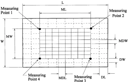
As a general rule, the least number of measurement points on a planar face is four. This is because three points uniquely determine a plane and a fourth point is needed to evaluate the deviation of the real surface from an ideal planar one. Let us first consider an ideal planar face of rectangular shape. A reasonable set of measurement points can be at four equally distributed positions, each having the distance of a fraction (e.g. one-fifth) of the corresponding length from the edges, as shown in Figure 1. The division of dashed grids in this figure is: DL = L/10 and
DW= W/10, where L represents the length and W
denotes the width of the rectangular plane.
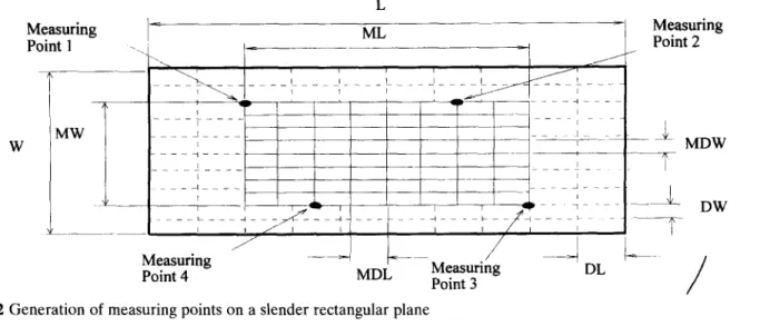
However, if this rectangular plane is of slender shape, i.e., say, the slenderness ratio L/W is over 4, the above arrangement will cause a long span of measurement points on the longer side. Therefore, a proper inward shift of two of the diagonal points (points 2 and 4) is necessary. For example, each side of the inside rectangle formed by the original four points can be subdivided by eight. Then two diagonal points are adjusted inward by two grids, as shown in
Figure 2, which has the following geometrical relations:
ML=L--4”DL MW=W-4”DW MDL = ML/8
MDW = MW/8 (1)
If the selected planar face is not an ideal one, e.g. it is non-rectangular or has some holes inside, the four measuring points as described above may fall outside of the real surface. A point searching scheme is proposed for this case. The aim is to find the closest point which is located within the planar face. This searching scheme starts with the initially generated measuring point that is outside the real surface. This point is shifted along the diagonal direction in a zigzag fashion if it is at a corner, as shown in Figure
3(a). This is called the Diagonal Search. The point is shifted along the direction normal to the edge, also in a zigzag fashion, if it is near an edge line, as shown in
Figure 3(b). This is called the Normal Search. The search sequence in Figzwe 3(a) is &, Al, AZ, A3, B,, B,, B,, Bd, B,, Cl,
Cz,
.
. . etc. until the point is inside the real surface. The search sequence in Figure 3(b) is A,.,, A,, AZ, A3, %, BO, B,, B,, B,, B,, Co, C,. . .a. Two typical examples showing the automatically generated measuring points for non-rectangular planar faces are given in Figure 4.Generation of measuring points on a cylindrical or conical face
The minimum number of measuring points for a cylindrical face is six and for a conical face is seven. For the purpose of geometrical symmetry, eight
Measuring Point 1 \ \ _ t ML Measuring ,/ Point 2 I I I , L Measuring Point 4 Point 3 MDW DW
Measuring Point 1 Measuring Point 2 Measuring Point 4 MDL Measurkg Point 3
Figure 2 Generation of measuring points on a slender rectangular plane
DL
/
measuring points which are evenly distributed on two circles at two different elevations along the axis are generated, as shown in Figure 5. The elevation of each measuring circle is at the one-fifth position from either end of the elevated length, which is the total length (H) subtracted by the probe’s radius (r) from both ends. Four measuring points are generated on each circle, with a separation of 90 degrees between
, Measuring point
i ./.
‘-u
i t
EdgeFigure 4 Examples of measuring points generation
Edge
A3
c3Ao: initial point
Ai , B i, C i: searching points (a)
(b)
1
.
.
.
oD3
oD1
0 DooD2
0 D4f
oc3 oc, oco oc2 oc4
lr
o*3 $1 o*o o% oB4 ,,_y--
{ p-f ?J 0
3 0 A4
.
Edge Figure 3 (a) Diagonal search; (b) normal search
two neighbouring points. The heights of the two circles (Figure 5) are:
h, = r + (H - 2r)/5
h, = r + 4( H - 2r)/5 (2)
Combined measuring points for a constructed object
The CAD model of a constructed three-dimensional object can be defined from the surface model or 2D projections of the 3D object’4.‘5. By using the
Figure 5 Measuring points on the surface of a cylinder or cone
46 Coordinate measuring machines: K-C Fan and M C Leu
methods of generating measuring points for planar, cylindrical and conical faces, the measuring points for a 3D object whose boundary is composed of these three kinds of surfaces can be generated by combining the measuring points for all the faces. A computer program has been written for generating the measuring points for 3D objects defined by Autocad. Figure 6 illustrates examples of the gener- ated points for 3D objects, with four measuring points generated for each planar face and eight measuring points generated for the cylindrical face.
User-dejined measuring points
In real industrial applications, the determination of an adequate number of points for a given feature is also very important. Different users may have different choices according to their experiences. The determination of an optimum number of measuring points for any given feature is a critical question which has not yet been studied in this research. In this developed system, however, an optional function is provided to the user who may switch from the automatic mode to the manual mode interactively on the screen. From this manual mode, the user can specify any number and the places of measuring points on the selected feature, as it is already repre- sented by the surface model. Figure 7 illustrates an example in which different measuring points have been manually selected by the user on two different planes, respectively.
Planned measuring
(a>
Figure 6 Examples of generation of measuring points on 3D objects
Figure 7 User-specified measuring points in the manual mode
Probe path planning
For probe path planning, one needs to consider the operation characteristics of a CMM. Some general rules useful to the path planning are:
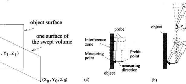
1. approaching the measuring point from the normal direction of the surface where the point is on 2. reserving a prehit distance before probing
3. preventing collision between the probe and the object.
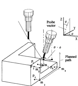
The probe path with respect to the specified measuring points on a plane could be generated utilizing the above rules. The probe is moved from a point in the workspace to the first prehit point at fast speed, then approaches the measuring point in slow speed. The prehit point has a prespecified distance from the measuring point in the normal direction of the measured surface. After four points have been touched in sequence, the probe is moved away from the plane. In practice, there are three kinds of planes: (1) a horizontal plane; (2) a vertical plane; and (3) an inclined plane. Figure 8 shows the generated probe path for an inclined plane, where m, is the starting
Figure 9 Probe path for a cylindrical face
point, p,, pZ, ps, p4, are the four measuring points, and m,, m2, m3, m4, are the corresponding prehit points.
In engineering drawing, a cylindrical or a conical feature may represent either a solid or a hole. The planning path must be generated in accordance with the feature. Since most CMM controllers do not provide the function of circular interpolation, there- fore, only linear interpolation is considered in this study. Figure 9 illustrates the probe path for the surface of a solid cylinder, where m, is the starting point, p,, . . . pR, are the eight measuring points, and m 1,. . . m,, are the corresponding prehit points. The probe paths for other features such as a solid cone or a cylindrical hole can be similarly generated.
Collision detection and avoidance
During the motion of the probe from the last measuring point of the current feature to the first measuring point of the next feature, the probe must not collide with the object. A proper strategy for the automatic collision avoidance is thus necessary. Such a strategy should start with collision detection. In this study, the probe collision detection is investigated by the use of swept-volume analysis, and the probe colli- sion avoidance is achieved by changing the probe orientation or introducing an intermediate point for the probe path.
Swept-volume analysis for collision detection
The probe can be considered as a solid object moving in the workspace of the CMM. During the movement its body moves along the path and generates a swept volume, as shown in Figure 10. Mathematically, the swept volume of a moving object M generated by the g-trajectory is:
S,(M) = 1 a,(x) : x E M, t @t,, t,l 1 (3)
swept volume
Figure 10 Swept volume of the moving probe
Detecting possible collisions between the probe and the workpiece can be done by checking whether the probe swept volume intersects the workpiece. This can be done effectively and efficiently by utilizing the theories of swept-volume analysis recently developed as described in Refs.16-18. A main idea is to parti- tion the boundary of the object M, &k?(t), into three parts: ingress, egress, and grazing points, i.e.
aM(t) = a_M(t)Ua+M(t)Ua,,M(t) (4)
where a-M(t) denotes the set of ingress points,
a+_M(t) denotes the set of egress points, and C&A4(t) denotes the set of grazing points, for any given time t. An ingress (egress) point is a point where the velocity points from the exterior (interior) to the interior (exterior). A grazing point is a point where the velocity line intersects the object M at a single point, which is the grazing point itself. Both the set of ingress points and the set of egress points form two-dimensional surfaces, while the set of grazing points forms a one-dimensional curve.
According to the theories of swept volumes for motions of non-deformable objects’6.‘7, the boundary of the swept volume of object M for an autonomous motion (such as pure translation or pure rotation) with the trajectory o can be expressed as:
=,(W = s,(a,M)Ua_M(t,)Ua+M(t,) (5)
Therefore, possible collisions between the probe and the workpiece can be checked by determining whether s&&44), the surface formed by the grazing curve &J4 for the o-trajectory, intersects with any of the boundary faces of the workpiece. Computation- ally, this can be done by first generating a discrete set of the initial grazing points and then determining whether the line segment traversed by each of these points intersects with any boundary face of the workpiece for the given o-trajectory.
Since the probe path in CMM inspection consists primarily of straight-line movements connected together, we can check possible collisions between the probe and the workpiece by determining whether the line segment traversed by each of the initial
48 Coordinate measuring machines: K-C Fan and M C Leu
grazing points of the probe intersects with any of the boundary faces of the workpiece, for each straight- line movement of the probe path. Each of the boundary faces of the workpiece can be a planar, cylindrical, or conical face, as before. We describe here only how to determine the existence of intersec- tion for a planar boundary face. The idea of checking the existence of non-null intersection for cylindrical and conical faces is the same, although the computa- tion is slightly more involved.
Let the concerned grazing point on the probe surface be (X0, Y,, Z,), and the velocity vector of the probe be [A B C]. The line traversed by this point can be expressed as follows:
x-x, Y-Yy, z-z, -~----__---_~
A B C (6)
Let the equation of the plane containing the concerned planar face on the workpiece be
aX+bY+cZ+d=O (7)
where a, b, c and d are constants. The intersection point (X1, Y1, 2,) between the line and the plane has the following relationship (see Figure II):
X,=X,+tA, Y,=Y,+tB, Z,=Z,+tC where (8) -(ax, + by,, + cZ, + d) t= Aa+Bb+Cc (9)
It is clear that the line segment intersects the planar face for the probe movement if (1) t,, St <tl; and (2) the point (X,, Y,, Z,) is inside the planar face. Other- wise, there is no intersection between them.
This kind of intersection checking should be assessed repeatedly for each traversed line segment of a grazing point with respect to each workpiece face. If there is no such point found throughout the search, then there is no collision with the workpiece during the movement of the probe. If such a point occurs at any time, then a strategy of collision avoid- ance must be applied, as discussed below.
object surface
one surface of
the swept volume
Figure 11 Intersection point on the surface
--- I +_’ ’
I
Interference :Gl zone II __ . objetC4
(b)Figure 12 Collision avoidance by probe rotation: case 1
Strategy for collision avoidance
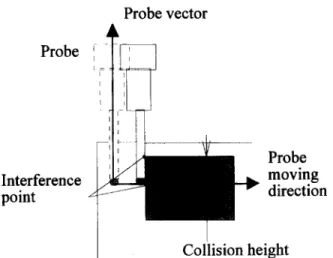
When the probe is moving deeply along a wall in order to measure the next point, the probe head may collide with the wall before its stylus ball can touch the target measuring point. There are two possible cases. In the first case, collision occurs in moving the probe to the prehit point of the next measuring point, as shown in Figure 12(a). In the second case, collision occurs in moving the probe from the prehit point to the measuring point, as shown in Figure 13(a). One way to avoid the collision is to rotate the probe to a different orientation, which is allowed by a motorized probe used with most CMMs. This is the first approach in our collision avoidance strategy. It is illustrated in Figure 12(b) and Figure 13(b).
The probe rotation method for collision avoidance may not work in many cases. For example, collision may occur when the probe is measuring different points of the same surface, such as that shown in
Figure 14 where the probe needs to move from one prehit point to another prehit point which is blocked by a protruded object. In order to avoid the collision, the probe has to detour its originally planned path.
Interference zone \ Measuring i point \ probe Prehit point (4 @I
Probe vector 4 Probe / I ‘P I’ Interference point Probe moving direction
I
Collision heightFigure 14 Collision between the probe and the measured
object
The second approach in our collision avoidance strategy is thus to introduce an intermediate point for the probe path, as shown in Figure 1.5. It is used when changing the probe orientation cannot provide a solution to the collision problem. This solution is also effective for probe collision avoidance in case the probe collides with the workpiece when it is moving from the current measuring surface to the next measuring surface, as illustrated in Figure 16. Colli- sion can be avoided if the probe moves up along its axis by at least h which is the least amount of lifting for the probe to be collision-free with the workpiece. In practice, a reasonable gap g is needed because of positional uncertainty. Again, collision can be avoided by introducing an intermediate point for the probe path.
Simulation of inspection path and probe motion
A simulation program of the CAD-directed inspec- tion for coordinate measuring machines has been developed. It starts with the workpiece design by
Moving direction
Changing direction
/ Lifting height
Figure 15 Collision avoidance by introducing an inter- mediate point
A
line
Figure 16 Planning for a new probe path
Probe vector
Z ?
Autocad on a personal computer. Once the surface model of an object is constructed, the measuring points are automatically generated with respect to each specified inspection surface. The motion path of the probe for the whole object is then generated with the consideration of collision avoidance between the moving probe and the inspected object. If a collision occurs, the strategy of collision avoidance is employed by either rotating the probe or introducing an intermediate point for the probe path. The probe moving along the collision-free inspection path can be animated on the computer screen.
Some examples of the simulation are given as follows. Figure 17 shows a CAD-directed probe path according to the approach described in Section 2 and Section 3. There is no occurrence of collision between the probe and the workpiece for the planned path. Figure 18 illustrates a different example, where the probe is tilted to avoid its collision with a side wall of the workpiece for the planned path. Figure 19
depicts the introduction of an intermediate point for the inspection path to avoid the probe colliding with a protruded block.
Concluding remarks
A method of CAD-directed inspection path planning has been developed for coordinate measuring machines. It is applicable to any object whose boundary is composed of planar, cylindrical, and conical faces. Following the principles of measure- ment of these types of surfaces, techniques for gener- ating the measuring points on them for a 3D object are proposed. These measuring points are then used to generate the probe inspection path. Possible colli- sions between the probe and the measured object for a given inspection path are detected by using the swept-volume analysis. A probe collision avoidance strategy is proposed for the case where a collision occurs for the initially planned probe path. A computer program has been written for implementing the developed method, and it has been integrated with Autocad software for use on a personal
50 Coordinate measuring machines: K-C Fan and M C Leu
Figure 17 Collision-free inspection path
computer. The integrated system has been demon- strated successfully with several typical examples. Compared with other systems developed on the workstation or mainframe computer, this system features low-cost, broad applicability, and collision- free inspection, and is especially attractive to small- and medium-sized companies.
Acknowledgements
The work reported forms part of a research program funded by the National Science Council of the Republic of China on the study of automatic 3D profile measurements. Professor M.C. Leu was on leave as a program director at the National Science Foundation in the United States when the paper was submitted.
Figure 18 Collision avoidance by probe rotation
Figure 19 Collision avoidance by introducing an inter- mediate point in the probe path
References
Hopp, X ‘CAD-directed inspection’, Annuls of the CZRP Vol 31
(1982) 421-425
hoppi TH ‘CAD-directed inspection’, Annals of the CZZW Vol
33 (1984) 357-361
Dutke, 64J et al. ‘CAD-directed inspection, error analysis and
manufacturing process compensation using tricubic solid database’, Annals of the CZZW Vol37 (1988) 149-152
Yau, HT and Meng, CH ‘An automated dimensional inspection
environment for manufactured parts using coordinate measuring machines’, Znt. .Z Prod. Res. Vol 30 (1992) 1517-1536
Eversheim, W and Auge, J ‘Automatic generation of part
programs for CNC-coordinate measuring machines linked to CAD/CAM systems’, Annals of the CZRP Vol 35 (1986) 341-345
lkaband, MT and Medeiros, DJ ‘CAD-directed programming
of a vision-based inspection system’, J. of Manufacturing System
Vo18 (1992) 215-223
Hsu, JLH, Juster, ND and De Pennington, A The selection of surfaces in inspection planning for coordinate measuring machines. Proc. 29th MATADOR Znt. Co& UK, 1992, pp. 321-328.
8 Hassan, JH et al. An intelligent link between CAD and automatic inspection. Proc. 29th MATADOR Int. Conf, UK. 1992, pp. 335-341.
13
9 Lee, SSG and Khoo, LP An approach to featured-based inspection planning, Proc. 29th MATADOR Int. Conf., UK, 1992, pp. 329-333.
14
10 Walker, I and WaIlis, AF ‘Application of 3-D solid modelling
to coordinate measuring inspection’, ht. J. Machine Tool and Manufactuting Vo132 (1992) 195-201
11 Meng, CH, Yau, HT and Lai, GY ‘Automated precision measurement of surface profile in CAD-directed inspection’,
IEEE Trans. on Robotics and Automation Vol 8 (1992) 268-218
15 16
17 12 Yau, HT, Meng, CH. Path planning for automated dimen-
sional inspection using coordinate measuring machines. Proc.
IEEE Int. Conf: on Robotics and Automation, 1991, pp. 1934-1939.
18
Lu, E, Ni, J and Wu, SM ‘An algorithm for the generation of
an optimum CMM inspection path’, Trans. of the ASME J. of Dynamic System, Measurement, and Control Vol 116 (1994) 396-404
May, C. J. Integration study from CMM to CAD. Masters Thesis, National Taiwan University, 1989.
Lomg, CY CAD-directed automatic inspection system. Masters Thesis, National Taiwan University, 1992.
Blackmore, D, Leu, MC and Wang, KK ‘Applications of flows
and envelopes to NC machining’, Annuls of the CIRP Vol 42 (1992) 493-496
Blackmore, D and Leu, MC ‘Analysis of swept volumes via
Lie groups and differential equations’, Int. Journal of Robotics Research Vol 11 (1992) 516-537
Blackmore, D, Leu, MC and Shih, F ‘Analysis and modeling
of deformed swept volumes’, Computer Aided Design Vol 26 (1994) 315-326