A Fully Digital Noncoherent and Coherent GMSK
Receiver Architecture with Joint Symbol Timing
Error and Frequency Offset Estimation
Yung-Liang Huang, Student Member, IEEE, Kong-Dar Fan, Student Member, IEEE, and Chia-Chi Huang
Abstract—We propose a fully digital noncoherent and coherent Gaussian minimum shift keying (GMSK) receiver architecture with joint frequency offset compensation and symbol timing recovery in this paper. Carrier phase offset can be estimated if the coherent demodulation mode is adopted.
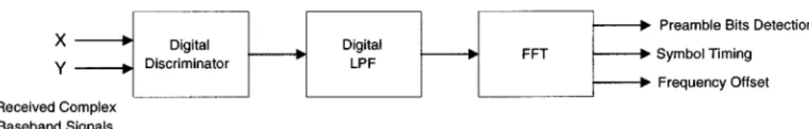
The converted base-band complex signal is first frequency dis-criminated and then passed through a digital filter which performs a fast Fourier transform (FFT). The frequency offset can be esti-mated from the dc component of the FFT, and the symbol timing error can be estimated from the phase angle of the FFT at a spec-ified frequency which is equal to an integral multiple of half the bit rate. These two estimated parameters are then used for fre-quency offset compensation and symbol timing recovery during a preamble period. Coarse carrier phase can be estimated by aver-aging sampled in-phase and quadrature-phase signals and finding its phase angle within the preamble period after carrier frequency offset is estimated and compensated. The bit error rate (BER) per-formance of this GMSK receiver architecture is assessed for an ad-ditive white Gaussian noise (AWGN) channel by computer simula-tion.
Index Terms—FFT, frequency offset compensation, GMSK, symbol timing recovery.
I. INTRODUCTION
F
REQUENCY shift keying (FSK) has long been used for data communication in a mobile radio environment. Min-imum shift keying (MSK) is a special form of FSK that has sev-eral good properties [1]. In 1981, Murota and Hirade proposed the use of a premodulation Gaussian low-pass filter to shape the spectrum of MSK [2]. This filter removes the sudden tran-sitions in the frequency modulation pulses of an MSK signal. The resulting Gaussian minimum shift keying (GMSK) mod-ulation thus achieves a narrower spectrum with much attenu-ated sidelobes. Furthermore, GMSK has the appealing feature that its spectral shape can be easily adjusted by a premodulation Gaussian low-pass filter. GMSK modulation is adopted in many wireless communication standards, such as the digital EuropeanManuscript received October 3, 1997; revised January 12, 1999. The syn-chronization algorithm described in this paper is patented under R.O.C. patent 073 745, 1995, and U.S. patent 5 867 059, 1999. This paper was partially pre-sented at the Seventh IEEE International Symposium on Personal, Indoor, and Mobile Radio Communications PIMRC’96, Taipei, Taiwan, R.O.C., Oct. 1996. Y.-L. Huang is with Solomon Wireless Technology Corporation, Taipei, Taiwan, R.O.C.
K.-D. Fan and C.-C. Huang are with the Wireless Communication Laboratory, Department of Communication Engineering, National Chiao Tung University, Hsinchu, Taiwan, R.O.C.
Publisher Item Identifier S 0018-9545(00)02577-9.
cordless telecommunications (DECT) system, the global system for mobile (GSM), and the cordless telephone-second genera-tion (CT-2) [3].
Demodulation of a GMSK signal has been an active research area since Murota and Hirade proposed their paper. Much of this research investigated noncoherent demodulation methods including frequency discrimination [4] and differential detec-tion [5]. Noncoherent demoduladetec-tion of a GMSK-modulated signal is simpler and less susceptible to random FM due to Rayleigh fading. On the other hand, coherent demodulation [2] achieves better system performance. In this paper, both noncoherent and coherent demodulation of a GMSK signal under a unified receiver structure are investigated.
Frequency offset and symbol timing error between a trans-mitter and a receiver are the most often encountered problems in a radio communication system [6]–[12]. They usually de-grade the radio system performance. When data is transmitted in a burst mode, it is especially important to find fast and ro-bust algorithms to estimate both frequency offset and symbol timing error in order to compensate for them. Estimation of car-rier phase offset is also necessary if coherent demodulation is used.
The required training sequence for frequency and symbol timing synchronization is usually called preamble bits. They are packed right before a unique word which is for frame chronization purposes. Both frequency and symbol timing syn-chronization have to be accomplished before the ending of a preamble. Theoretical approaches use maximum a posteriori (MAP) or maximum-likelihood (ML) criterion to jointly esti-mate carrier phase, frequency offset, and symbol timing [1]. However, they are generally too complicated to be realized or commercialized. A simpler, robust, and suboptimal architecture would be preferred in practice if its performance is acceptable. In this paper, we propose a receiver architecture which uses fast Fourier transform (FFT) results to estimate symbol timing error, frequency offset, and phase offset jointly.
In our receiver, symbol timing sychronization is done in a strictly feedforward manner, thereby eliminating the adjustment of A/D sample timing. Our frequency offset compensation is a hybrid approach. On one hand, the frequency offset estimation can be fed back to a voltage-controlled oscillator (VCO) during a preamble period such that the long-term frequency drift can be compensated. On the other hand, our frequency offset com-pensation can also be done in a feedforward manner. Moreover, the frequency offset estimation can be used to adjust the deci-sion threshold when a noncoherent detection mode (that is, a
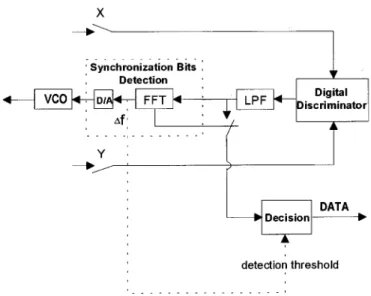
Fig. 1. Block diagram of our synchronization method.
frequency discriminator in this paper) is adopted and rotate the signal constellation if a coherent detection mode is adopted.
Most existing GMSK receivers adopt a conventional hetero-dyne architecture. We proposed a low IF GMSK noncoherent receiver architecture in [13]. In this paper, we add a coherent demodulation mode to this receiver architecture for its potential use in high-speed wireless communication systems.
In the next section, we describe the proposed algorithm for symbol timing error and frequency offset estimation. In Sec-tion III, we verify that the synchronizaSec-tion algorithm is suitable for GMSK demodulation. In Section IV, we introduce a hybrid receiver architecture which includes both a noncoherent and a coherent demodulation mode. The performance of this receiver architecture is investigated by computer simulation. Simulation results for an additive white Gaussian noise (AWGN) channel are given in Section V. Finally, some conclusions are drawn in Section VI.
II. THESYNCHRONIZATIONALGORITHM
In this section, we describe our method to recover carrier fre-quency and symbol timing simultaneously [14], [15]. The sim-plified block diagram of our synchronization method is shown in Fig. 1.
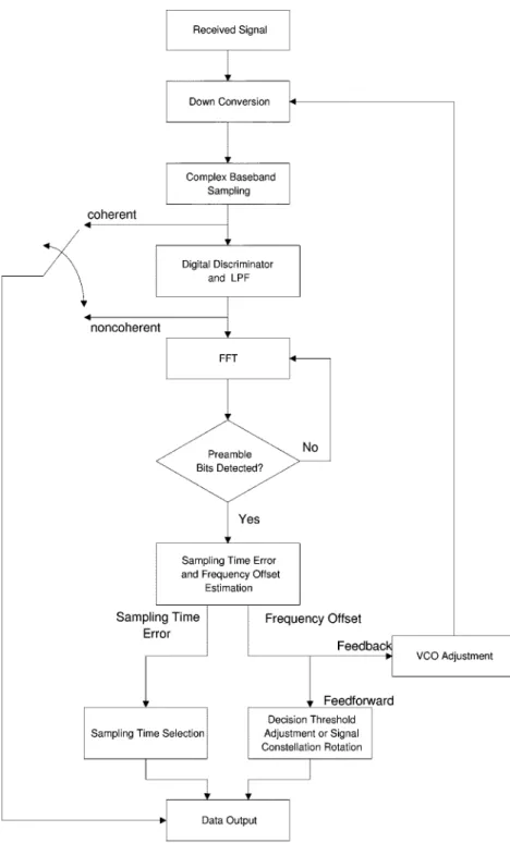
Assume that we first convert the received signal from radio frequency (RF) to baseband and the real and imaginary compo-nents of the base-band complex signal are and . These two signals are oversampled, digitally frequency discriminated, and low-pass filtered to obtain raw digital data. This data goes through an FFT for synchronization preamble bits detection. If detected, both frequency offset and sampling time error are es-timated from the FFT results. Symbol timing sychronization is done in a feedforward manner. Carrier frequency offset com-pensation is done in a hybrid manner. On one hand, frequency offset estimation is fed back to a VCO during the preamble pe-riod. On the other hand, this estimation can be used to change the decision threshold in a noncoherent detection mode or rotate the signal constellation in a coherent detection mode. After syn-chronization is finished, we obtain the demodulated data. The whole synchronization and data detection process can be un-derstood in more detail by examining the flowchart shown in Fig. 2.
Here, we consider a continuous-phase frequency shift keying (CPFSK) modulation in general. We assume that the received signal is not distorted by the channel and the predetection filter and it is denoted by
(1)
where is an additive bandpass Gaussian noise with one-sided power spectrum density , and are bit energy and bit period, is a sampling period, is an arbitrary phase, is the frequency-modulated phase of the transmitted car-rier, and is the time delay caused by channel filtering and corresponds to a time delay at which the signal should be sam-pled. Here, is rounded off to an integer for implementing the synchronization algorithm digitally. We know can be ex-pressed as
(2) and is an equivalent base-band representation of
.
Without loss of generality, is limited to the interval [ , ]. Ignoring the noise, the in-phase and quadra-ture-phase components of demodulated complex base-band signals are
(3)
(4) where and are the frequency offset and the phase offset produced by the receiver VCO at a center frequency . If we send and into a base-band frequency discriminator, the discriminator output signal is
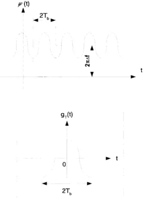
(5) When a training sequence is received, the dis-criminator ouput signal will be periodic with a period of . An example of this waveform is depicted in Fig. 3. From Fig. 3, we observe that this waveform consists of a dc term and a pe-riodic component , with a period of , where is a dc-free waveform of du-ration and is centered at the origin. If we observe for periods, it can be expressed as the following:
is a positive integer (6) Let be sampled every s and the samples be denoted by
Fig. 2. A flowchart of receiver synchronization and data detection.
where denotes the sample of at . It is noted that has a period of .
Let and define an -point discrete Fourier trans-form (DFT) of as1
(8)
19[1] denotes the discrete Fourier transform whereas 9(1) denotes
contin-uous-time Fourier transform.
It is shown in the Appendix that if is even and real with zero dc, then the frequency offset and sampling time error
can be estimated by
(9)
(10) Meanwhile, the magnitude of (or equivalently ) can be compared with a signal detection threshold to determine
Fig. 3. An example of periodic waveform at the discriminator output.
whether a training signal (i.e., a preamble or synchronization bits) has arrived or not.
This joint symbol timing and frequency offset recovery method can be applied to any CPFSK modulation. In the next section, we will explain this method in more detail using GMSK, which is a special case of CPFSK, as an example.
III. APPLICATION TOGMSK
After describing our synchronization algorithm, we now apply it to GMSK modulation. We show that the basic pulse of a GMSK signal is real and even and has zero dc value such that both (9) and (10) can be used. Besides, we also show that the presence of a GMSK preamble can be detected using the synchronization algorithm.
For GMSK, in (1) can be expressed as
(11) if a “ ” sequence is transmitted. Here, is the fre-quency pulse at the output of a Gaussian low-pass filter with an impulse response when a square pulse (with a duration of one bit period and a magnitude of ) is the input, i.e.,
(12) where
otherwise
(13) (14)
is the 3-dB bandwidth of the Gaussian low-pass filter and the operator “ ” denotes convolution. Thus
(15) where is defined as
(16) Since is real and even, it is easy to observe from (11) that the basic pulse of is real and even with zero dc.
A. GMSK Preamble Detection
Taking the Fourier transform of , we get
(17)
Comparing (17) with the Poisson’s sum formula of a periodic signal, it is easy to deduce that in (6) has a Fourier trans-form at frequency
even
odd. (18) It is also easy to show the relationship between the DFT of
and the Fourier transform of is
(19) The approximation is valid if is negligible for
TABLE I
Fig. 4. A low IF radio modem architecture.
It is known that a Fourier transform of the convolution of two functions is the product of their individual Fourier transform
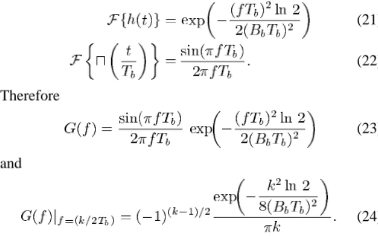
(20) Through some simple calculation, the Fourier transforms of and can be derived
(21) (22) Therefore (23) and (24) Table I illustrates typical values of calculated by (24). Only values associated with positive are shown, and it is easy to verify that equals since is real and even. can be calculated using Table I and (19).
It is observed that decreases very fast when is increased for small . So does . In general, the tone at dominates when is smaller than 0.5. We point out in the Appendix that the th term in the FFT of corresponds to the component in the
Fourier transformation of . Hence, the magnitude of ( ) is helpful to the determination of the presence of an incoming preamble or synchronization bits.
The receiver always monitors the magnitude of to de-termine the occurrence of preamble bits. The threshold used to determine the preamble bits should have been determined by . However, we found from our simulation that the threshold can be set to about 0.6 [can be calculated from (19) and Table I], and this level is not sensitive to . In other words, this threshold can be chosen in such a way that pre-amble bits can always be detected when the receiver is above its sensitivity level in all our simulated cases.
IV. ANADAPTIVERECEIVERARCHITECTURE
Low power, low cost, and small size are important features of a mobile/personal communication handset. Therefore, a highly integrated RF front–end and base-band transceiver architecture is desired. A promising architecture for implementing a radio transceiver is a low IF configuration [16]. A low IF GMSK modem architecture proposed by the authors [13] is shown in Fig. 4. With a low IF architecture, the problems of dc offset and flicker noise associated with a direct conversion receiver architecture are greatly eliminated. However, a new problem of image rejection of the relatively close-in image frequency is in-troduced. This image frequency must be eliminated through the use of an image rejection mixer [17].
The digital complex sampler [18] in Fig. 4 uses an IF sam-pling technique to produce base-band I and Q signals. A digital base-band noncoherent demodulator with joint symbol timing
Fig. 5. Digital base-band noncoherent demodulator with joint symbol timing error recovery and frequency offset compensation.
error recovery and frequency offset compensation is shown in Fig. 5.
Adaptive modulation techniques are introduced in [19] to achieve high-speed wireless communications. It was proposed that a high-rate modem (less power efficient) be used when a mobile terminal (MT) is near its base station (BS) and a low-rate modem (more power efficient) be used when the dis-tance between an MT and a BS is large. Adaptive modulation schemes have the advantages of providing larger coverage area and smaller outage probability in a cellular system.
Adaptive GMSK modulation (with varying from 0.25 to 0.5) can be realized by adjusting the bandwidth of a premod-ulation Gaussian low-pass filter, especially when this modula-tion is implemented in an IQ approach [20]. In this case, only the ROM table realizing the frequency modulation path needs to be changed.
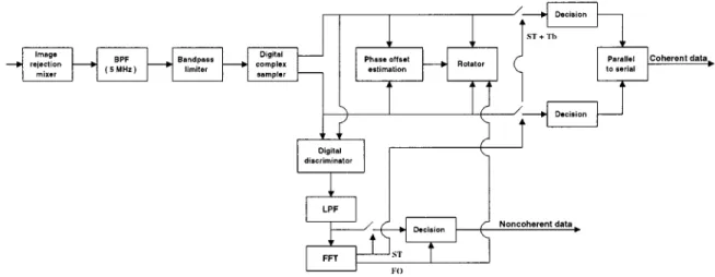
With some modifications of Fig. 5, we propose a hybrid re-ceiver architecture which consists of both a noncoherent and a coherent demodulator, as shown in Fig. 6. This hybrid receiver functions as an adaptive receiver. It uses a noncoherent demod-ulator (less power efficient) with when the link is first established and uses a coherent demodulator (more power efficient) when carrier synchronization is settled. Furthermore, a can be used to achieve higher data rate transmis-sion with the coherent demodulation mode. The performance of this hybrid receiver is evaluated in Section V by computer sim-ulation.
V. SIMULATIONRESULTS ANDRECEIVERPERFORMANCE
The performance of the hybrid receiver for GMSK modula-tion in an AWGN channel is investigated by computer simula-tion. Effects of intersymbol interference (ISI) introduced by IF filtering, timing error, and frequency error are evaluated in our simulation.
In the simulation of the noncoherent demodulator, we adopted which introduces ISI less significantly.
A frequency offset up to 25 KHz is expected which corre-sponds to a 10-ppm inaccuracy of a 2.4-GHz oscillator. System performance degradations at bit error rate (BER) were investigated for voice communication purposes.
In the simulation of the coherent demodulator, we used which has better spectral efficiency but in-troduces more ISI than the case. Assume that stable oscillators are used at both the transmitter and the receiver. Doppler shift can be neglected for indoor application at 2.4 GHz in general. The same frequency offset of up to 25 KHz is assumed and system performance degradations at BER
is investigated.
The Monte Carlo simulation method is used to obtain the BER. We assume a TDMA/TDD frame structure with a frame period of 20 ms. The bit period is 10 s and the sampling rate is 16 MHz. We assume a data packet consists of 500 b and begins with a 16 b of preamble. The magnitude of is mon-itored and compared with a threshold at a receiver to determine the presence of preamble bits and hence the coming of a data packet. This threshold is chosen in such a way that preamble bits can be detected at the receiver’s sensitivity. After recognizing the occurrence of preamble bits symbol timing and frequency offset are jointly estimated using the remaining preamble bits. As soon as the magnitude of drops below the threshold, the estimation procedure is stopped. The bit errors in the detected data packets are counted and at least 10 data bits are simulated to obtain a steady-state BER.
A. Noncoherent Demodulator
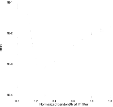
The bandwidth of the receiver IF filter is evaluated according to the tradeoff between ISI and noise. The narrower the filter bandwidth is, the more out-of-band noise is rejected and the more ISI is introduced. Due to frequency offsets, an analytical determination of an optimum IF bandwidth is difficult. We evaluate the effect of on BER in our simulation assuming perfect synchronization.
The effect of on BER for noncoherent GMSK demodula-tion is shown in Fig. 7 when and dB. We observe that the performance of the noncoherent demodu-lator is sensitive to and the optimum normalized bandwidth is about 0.5. The existence of frequency offset will push part of the desired signal out of the passband of the receiver filter. Therefore, the normalized receiver filter bandwidth should be somewhat larger than the optimum value of 0.5 to enable the carrier and timing recovery circuits cope with the frequency offset. For this reason, a wider bandwidth of is chosen for the receiver IF filter to cope with a frequency offset up to 50 KHz.
Bit synchronization cannot be ideal in practice. The normal-ized sampling timing error (STE) is denoted by , where in the sampling time error, positive for sampling time advance and negative for sampling time delay. Fig. 8 shows the BER performance of the noncoherent demodulator using STE as a parameter. Note that the curve corresponding to STE has about 4-dB degradation relative to the static BER perfor-mance of a coherent GMSK with and
as obtained from [2], in which ideal synchronization had been assumed. It is also noted that the STE needs to be smaller than
Fig. 6. A hybrid receiver architecture with joint symbol timing error recovery and frequency offset compensation.
Fig. 7. The effect of the receiver IF filter bandwidth on BER for noncoherent GMSK demodulation (B T = 0:5, E =N = 12 dB).
0.125 for degradation less than 2 dB at BER . Notice that the BER performances are different for STE values of opposite sign. It has to be noticed that FM is a nonlinear mod-ulation and a band-limiting predetection filter has been used. Therefore, the basic FM-demodulated pulse shape might not be symmetric. On the other hand, it is indicated in [21, p. 63] that when a channel has a nonlinearity, the received eye patterns might not be symmetric. This is the reason why the BER per-formances of noncoherent GMSK are different for STE values of opposite sign.
Timing acquisition with our joint estimation algorithm in a single burst is simulated and the results are shown in Fig. 9. We observe that the symbol timing estimation with only 12 b of preamble satisfies the requirement as described above. The STE is even down to 0.1 when 16 b of preamble is used. This STE estimation can be further improved by averaging over several consecutive single-burst estimates.
Fig. 8. The effect of sampling time error on BER for noncoherent GMSK demodulation (B T = 0:5, B T = 0:55). The curve for coherent GMSK with ideal synchronization is obtained from [2].
With our joint estimation method, the frequency offset esti-mation error with a single burst is shown in Fig. 10. The stan-dard deviation of the frequency offset estimation error is about 5 KHz. This error is expected to be acceptable because it is much less than the operation bandwidth of the discriminator.
The BER simulation results under the assumption of a 16-b preamble are shown in Fig. 11. Frequency offsets of
and are assumed for the light solid line and the dashed line, respectively. The amount of the frequency offsets is about 25 ppm at a 2.4-GHz carrier frequency, assuming a data rate of 1 Mb/s. The perfect synchronization case (dark solid line) is also shown in Fig. 11. It is observed that with our synchroniza-tion algorithm the receiver performance is close to the perfect synchronization case.
Summarizing the above simulation results, we conclude that with a preamble of 16 b we can use the noncoherent demodu-lator as shown in Fig. 5 in a burst-mode GMSK ( ) receiver even when a normal frequency offset occurs, and the BER degradation is small.
Fig. 9. Timing acquisition performance with a single burst (B T = 0:5).
Fig. 10. Frequency offset estimation error for GMSK with a single burst (B T = 0:5).
B. Coherent Demodulator
The bandwidth of the receiver IF filter for a coherent GMSK demodulator is investigated and the result is shown in Fig. 12. It is observed that a normalized bandwidth of 0.3 results in better performance when . However, this is true only
Fig. 11. The BER performance for noncoherent GMSK demodulation with 16 b of preamble (B T = 0:5).
Fig. 12. The effect of receiver IF filter bandwidth on BER for coherent GMSK demodulation (B T = 0:25, E =N = 8 dB).
when the signal spectrum is not shifted, i.e., when the frequency offset is zero. In order to mitigate the effect of frequency offset a wider receiver IF filter bandwidth is chosen at the expense of including more noise. A normalized bandwidth of 0.5 is chosen in the following simulation.
Bit synchronization performance is also investigated. Fig. 13 shows the BER performance of a coherent GMSK demodulation using STE as a parameter. Note that the curve corresponding to STE is close to the static BER performance of a coherent GMSK with and as shown in the Fig. 13 of [2], in which ideal synchronization had been assumed. It is observed that the effect of STE is less severe than the non-coherent architecture case since a base-band pulse period is two
Fig. 13. The effect of sampling time error on BER for coherent GMSK demodulation (B T = 0:25, B T = 0:5). The curve for reference is obtained from [2].
Fig. 14. BER performance under the effect of residual frequency offset for coherent GMSK demodulation (B T = 0:25).
times the bit period with coherent detection. degradation is less than 0.5 dB at BER even when STE approaches
0.25.
The constellation of the complex base-band signal rotates due to frequency offset and thus introduces decision error. Assuming no phase offset initially, the BER performance of a single data packet due to a small frequency offset is shown in Fig. 14. We observe that degradation is about 1 dB at BER
when the residual frequency offset (RFO) is only 100 Hz. There is an 18 phase offset at the end of a data packet in this case. It means that RFO must be kept below 100 Hz if coherent detec-tion is to be adopted. Referring to Fig. 10, we observe that the
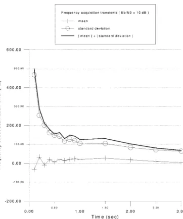
Fig. 15. Frequency acquisition transient for GMSK (B T = 0:5, frequency offset= 20 KHz).
frequency offset estimation error is too large with a single burst for coherent detection to work at the beginning of a radio link connection.
We assume carrier frequencies are generated by synthesizers using stable oscillators and the Doppler rate is negligible. (The Doppler rate is under 10 Hz for indoor applications at 2.4 GHz in general.) As a result, we can improve the accuracy of our algorithm by averaging a number of consecutive single-burst estimates. Fig. 15 shows the frequency acquisition transients of our estimation algorithm based on averaging. We observe that after 2 s (100 data packets) of averaging, the frequency offset estimation error satisfies the requirement of RFO being less than 100 Hz. Frequency offset estimation error after 3 s (150 data packets) of averaging under the effects of different frequency offsets are shown in Fig. 16. It is observed that the frequency offset estimation errors are all below 100 Hz. Hence, with the aid of a carrier tracking loop, coherent detection is possible as long as our frequency offset estimates are averaged for 3 s.
Coherent detection requires the exact phase information of the carrier. After frequency offset is estimated and compensated, we can estimate the carrier phase by the following:
(25)
where is the index for the samples of preamble bits and are sampled in-phase and quadrature signals, re-spectively. The carrier phase offset is then estimated by sub-stracting from the estimated carrier phase. The carrier phase
Fig. 16. Frequency offset estimation error after 150 data packets of averaging for GMSK under the effects of different frequency offsets (B T = 0:5).
Fig. 17. Carrier phase offset estimation with a single burst (B T = 0:25).
offset estimation error with a single burst is shown in Fig. 17. We observe that the estimation error with a single burst is only about 3 and its effect is negligible. Thus, we can achieve co-herent detection in each burst and expect that BER degradation
will be only in the order of 1 dB (as shown in Fig. 14) with our synchronization algorithm.
VI. CONCLUSION
A hybrid GMSK receiver architecture with joint frequency offset and symbol timing estimation is presented. Typical syn-chronization problems including frequency offset and symbol timing error are investigated and solved by applying an FFT al-gorithm on the frequency discriminated base-band signal. Car-rier phase offset can be estimated after carCar-rier frequency is es-timated and compensated.
The BER performance of our GMSK receiver architecture is assessed in an AWGN channel by computer simulation. Simula-tion results show that our receiver requires only a 12 b of training preamble in the noncoherent demodulation mode and its per-formance is suitable for burst-mode data communications. This receiver architecture can also achieve better BER performance with coherent detection because both carrier frequency offset and carrier phase offset can be estimated accurately.
APPENDIX
Following the same notation as in [22], we define
(26) and
otherwise. With this definition we have
(27) Substitute (7) and (27) into (8)
where
. -point DFT
The third row in (28) is derived by applying the circular shift property of DFT [22] to the second row
-point DFT
is some integer It can be easily shown that
otherwise
for the range over which we are concerned. Thus, (28) becomes
(29) It is noted that equals to zero if is not a multiple of . Letting , (29) becomes
(30) Letting ,2 (29) becomes
(31) Therefore, we can estimate the frequency offset by (30) and the sampling time error by (31) as long as does not vanish at . From (30)
(32) In fact, the first term in this estimator is just a sample mean
. From (31)
(33)
2k = L in DFT of [n] corresponds to f = L=N 1 1=T = 1=2T in
Fourier transformation of (t). This is consistent with our experience that there is a tone at the fundamental frequency of1=2T in Fourier transform when a signal is periodic with a period of2T .
If is even and real with zero dc, then the above two esti-mators can be simplified and become
(34) (35)
REFERENCES
[1] J. B. Anderson, T. Aulin, and C.-E. Sundberg, Digital Phase
Modula-tion. New York: Plenum, 1986.
[2] K. Murota and K. Hirade, “GMSK modulation for digital mobile radio telephony,” IEEE Trans. Commun., vol. COM-29, pp. 1044–1050, July 1981.
[3] K. Feher, “Modems for emerging digital cellular–mobile radio system,”
IEEE Trans. Veh. Technol., vol. 40, pp. 355–365, May 1991.
[4] S. M. Elnoubi, “Analysis of GMSK with discriminator detection in mo-bile radio channels,” IEEE Trans. Veh. Technol., vol. VT-35, pp. 71–76, May 1986.
[5] M. K. Simon and C. C. Wang, “Differential versus limiter-discriminator detection of narrow-band FM,” IEEE Trans. Commun., vol. COM-31, pp. 1227–1234, Nov. 1983.
[6] C.-C. Huang, Y.-L. Huang, and C.-R. Sheu, “Synchronization method and apparatus for guard interval-based OFDM signals,” U.S. patent pending.
[7] Y.-L. Huang, C. H. Lu, J.-S. Yu, and J.-D. Shih, “One bit differential de-tector with frequency offset compensation,” U.S. patent 5 448 594, 1995. [8] Y.-L. Huang, C.-C. Lu, and C.-C. Huang, “Synchronization system of digital audio broadcasting (DAB) receiver,” in Proc. Int. Conf. Consum.
Electr., June 1997, pp. 370–371.
[9] , “Synchronization method and system for a digital receiver,” U.S. patent pending.
[10] M. Luise and R. Reggiannini, “Carrier frequency recovery in all-digital modems for burst-mode transmissions,” IEEE Trans. Commun., vol. 43, pp. 1169–1178, Feb./Mar./Apr. 1995.
[11] K. Matsuyama et al., “A burst GFSK-modem for wireless LAN sys-tems,” in PIMRC’95, Oct. 1995, pp. 198–202.
[12] R. Mehlan, Y.-E. Chen, and H. Meyr, “A fully digital feedforward MSK demodulator with joint frequency offset and symbol timing estimation for burst mode mobile radio,” IEEE Trans. Veh. Technol., vol. 42, pp. 434–443, Nov. 1993.
[13] Y.-L. Huang and C.-C. Huang, “A low IF GMSK modem architecture with joint symbol timing recovery and frequency offset compensation,” in PIMRC’96, Oct. 1996, pp. 281–285.
[14] C.-C. Huang, Y.-L. Huang, and K.-D. Fan, “A demodulation receiving system with joint frequency offset and symbol timing error estimation using FFT,” R.O.C. patent 073 745, 1995.
[15] , “Demodulating system for MSK and GMSK signals using a fast Fourier transform converter,” U.S. patent 5 867 059, 1999.
[16] P. R. Gray and R. G. Meyer, “Future directions in silicon ICs for RF per-sonal communications,” in IEEE Proc. 1995 Custom Integrated Circuits
Conf.
[17] L. Pandula, “Image reject and image canceling mixers,” RF Design, Apr. 1995.
[18] G. J. Saulnier, C. M. Puckette IV, R. C. Gaus, Jr., R. J. Dunki-Jacobs, and T. E. Thiel, “A VLSI demodulator for digital RF network applica-tions: Theory and results,” IEEE J. Select. Areas Commun., vol. 8, pp. 1500–1511, Oct. 1990.
[19] N. Morinaga, M. Nakagawa, and R. Kohno, “New concepts and tech-nologies for achieving highly reliable and high-capacity multimedia wireless communications systems,” IEEE Commun. Mag., vol. 35, pp. 34–40, Jan. 1997.
[20] J. J. J. Haspeslagh et al., “A 270-kb/s 35-mW modulator IC for GSM cellular radio hand-held terminals,” IEEE Trans. Solid-State Circuits, vol. 25, pp. 1450–1457, Dec. 1990.
[21] R. W. Lucky, J. Salz, and E. J. Weldon, Jr., Principles of Data
Commu-nication. New York: McGraw-Hill, 1968.
[22] A. V. Oppenheim and R. W. Schafer, Digital Signal Pro-cessing. Englewood Cliffs, NJ: Prentice-Hall, 1975.
Yung-Liang Huang (S’93) was born in Taipei, Taiwan, R.O.C. He received the B.S. and M.S. degrees in 1985 and 1987, respectively, both in communications, and the Ph.D. degree in 1999, all from National Chiao Tung University (NCTU), Hsinchu, Taiwan.
In 1987, he joined the Electronics Research and Services Organizations (ERSO) and later the Computer and Communication Laboratories (CCL), both at the Industrial Technology Research Institute (ITRI), where he was involved in the development of the V.32 modem data pump, video compression, DECT, and Eureka 147 DAB systems. He was the Project Leader of both the video compression and DECT projects. Since 1998, he has been with the Solomon Wireless Technology Corporation, Taipei, as a Senior Project Manager, working on various frequency hopping communication systems. His interests include the design and implementation of communication systems and spread spectrum for wireless communications.
Kong-Dar Fan (S’95) was born in Taipei, Taiwan, R.O.C., in 1969. He received the B.S. degree in con-trol engineering in 1992 and the M.S. degree in com-munication engineering in 1995, both from National Chiao Tung University (NCTU), Hsinchu, Taiwan. He is currently working toward the Ph.D. degree at NCTU.
His research interests include wireless medium ac-cess protocol, slow frequency hopping spread-spec-trum systems, and personal communications.
Chia-Chi Huang was born in Taiwan, R.O.C. He re-ceived the B.S. degree from National Taiwan Univer-sity, Taiwan, in 1977 and the M.S. and Ph.D. degrees from the University of California, Berkeley, in 1980 and 1984, respectively, all in electrical engineering.
From 1984 to 1988, he was an RF and Com-munication System Engineer with the Corporate Research and Development Center, General Electric Company, Schenectady, NY, where he worked on mobile radio communications. From 1989 to 1992, he was with the IBM T. J. Watson Research Center, Yorktown Heights, NY, as a Research Staff Member working on indoor radio communications. Since September 1992, he has been with the Department of Communications, National Chiao Tung University (NCTU), Hsinchu, Taiwan, as an Associate Professor.