Analysis of the Parameters of the Sintered Loop Heat Pipe
K.J. Zan,1 C.J. Zan,1 Y.M. Chen,1 and S.J. Wu2 1
Department of Mechanical Engineering, National Taiwan University, Taipei, Taiwan 2
Department of Weapon System Engineering, Chung Cheng Institute of Technology, National Defense University, Taoyuan, Taiwan
The purpose of this paper is to establish an experimental formula for sintered dendritic nickel powder. For this reason, wick structures with different porosity ranging from 65 to 80% were fabricated by cold pressing sintering process at fixed porosity and their parameters that included porosity, pore radius, and permeability were also measured. According to both the capillary limitation and the present experimental formula of the sintered dendritic nickel powder, the wick structure parameters that would affect the heat transfer capacity of the loop heat pipe (LHP) were analyzed theoretically and then investigated experimentally. The results showed that there exists an optimal combination of wick structure parameters by which the performance of the LHP would achieve optimization. The maximum heat transfer capacity was up to 500 W and the thermal resistance was 0.12 °C/W at the allowable working temperature 80 °C. © 2004 Wiley Periodicals, Inc. Heat Trans Asian Res, 33(8): 515–526, 2004; Published online in Wiley InterScience (www.interscience. wiley.com). DOI 10.1002/htj.20034
Key words: loop heat pipe, wick structure, pressing sintering
1. Introduction
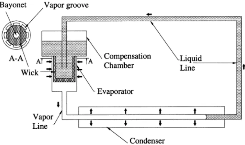
The loop heat pipe (LHP) technology was first developed by Maidanik in the early 1970s and patented in the U.S. in the mid-1980s [1]. The LHP is a capillary pumped, two-phase, fluid-thermal management system which uses a fluid’s latent heat of vaporization to efficiently transfer heat from a heat source to a radiator. Figure 1 is the schematic of a typical LHP. A typical LHP system is composed of evaporator, condenser, compensation, vapor line, and liquid line. Only the evaporator section has a porous wick structure, and other components are constructed by smooth tubes.
As shown in Fig. 1, heat is applied to the evaporator. Vapor is generated at the interface between wall and wick surface and is then collected by vapor grooves. The capillary force of the wick structure is used to pump the vapor through the vapor line to the condenser. After being condensed, working liquid returns to the evaporator through the liquid line. Attached to the evaporator is a Heat Transfer—Asian Research, 33 (8), 2004
compensation reservoir that provided a storage location to accommodate the changes in system inventory at different operating conditions.
The LHP in this general configuration has demonstrated the ability to transport heat over long distances against gravitation and to be self-priming. The LHP is hence considered a highly efficient heat transfer device with a considerable potential for development and application in various fields.
According to the literature, the key features relevant to the performance of LHP are the wick structure parameters that included pore radius, porosity, and permeability [2]. However, their effects are different and implicated. In order to enhance the performance of the LHP, it is necessary to discover their mutual implication. Here, dendritic powder is selected, because it has higher porosity than spherical powder [3, 4]. To find out the optimal combination of the above parameters, the present effort seeks to establish the experimental formula for sintered dendritic powder, since only the formula about sintered spherical powder was mentioned in the literature [5]. For this reason, wick structures with different porosity ranging from 65 to 80% were fabricated by cold pressing sintered process at fixed porosity and their parameters were also measured. Next, according to the capillary limitation and the present experimental formula of the sintered dendritic powder, the various porosity wick structures that would affect heat transfer capacity of the LHP were analyzed theoretically. Further-more, experiments are conducted to test the LHP performance that included heat transfer capacity and thermal resistance.
Nomenclature
D: tube diameter, mm
g: gravity, m/s2
H: vertical height between the axes of evaporator and condenser, m
Kw: permeability, m2
L: length, mm
m.: mass flow rate, kg/s
P: pressure, Pa
Q: heat transfer rate, W
R: thermal resistance, °C/W
rc: pore radius, m
rh: hydraulic radius of vapor groove, mm
Tc,ave: average temperature of condenser, °C
Tc,in: temperature of the condenser inlet, °C
Tc,out: temperature of the condenser outlet, °C
Te,ave: average temperature of evaporator, °C
hfg: latent heat of vaporization, W/g
ε: porosity, %
µ: absolute viscosity, kg/(m ⋅ s)
ρ: density, kg/m3
σ: surface tension, N/m
Ψ: included angle between the axes of evaporator and condenser, rad Subscripts
c: condenser
cap: capillary
eff: effective
g: gravity
groove: vapor groove
i: inner
l: liquid
ll: length of liquid line
o: outer
phase: phase change
r: real
sinter: sinter blank
vl: length of vapor line
w: wick
2. Description of the LHP System
Before conducting the study on wick parameters, the designing and fabricating of LHP must be described in advance. In order to serve as the thermal barrier between vapor grooves and evaporator core, sintered nickel powder was considered a suitable material for wick structure, since it has low thermal conductivity. To find out the experimental formula for different shape of powder, the Inco type 255 nickel dendritic powder was selected. Moreover, the choice of a working fluid should be made with allowance for higher value of dP/dT within the operating temperature range. Ammonia was hence chosen, even though its Merit Number and capillary height are a little lower than water.
The specifications of the other components such as evaporator, condenser, liquid line and vapor line, and compensation chamber are listed in Table 1. Here, stainless steel was chosen as the material of tube and outer casing, because it is compatible with ammonia. The detail designing and
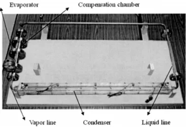
fabricating processes can be found in Cheng’s study [6]. Moreover, the fabricated LHP system is shown in Fig. 2.
3. Fabrication of the Wick Structure
In general, two major methods for sintering pore structures that included loose powder sintering process and cold pressing sintering process could be selected. The advantage of loose powder sintering process is that a sintered pore structure, with a simple shape such as cylinder and plank, can be made by simple molds. But the properties of the pore structures are not easy to control. On the
Fig. 2. The fabricated LHP system.
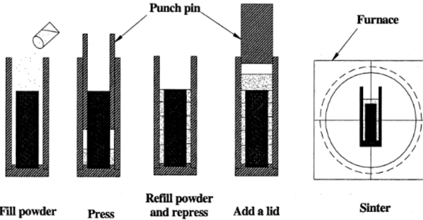
contrary, with the process of cold pressing sintering, the strength of the sintered blank can be intensified, and complicated shapes of sintered pore structure can be fabricated. Furthermore, the properties of the pore structure also can be controlled. However, complicated pressed processes are its drawback. In order to control wick structure parameters effectively, the wick was fabricated by the cold pressing sintering process at fixed porosity.
The fabrication procedure of cold pressing sintering process at fixed porosity is shown in Fig. 3. In the present study, the shape of wick structure is a cylinder. In order to avoid the green strength being non-homogenized, the compact ratio of height to diameter should be taken into account. Hence, the blank must be divided into several parts, and the powder was filled into the mold and pressed by punch step by step. Before filling the dendritic nickel powder into the mold, the filled quantity of each sectional volume must be calculated first. The quantity of filled powder (mpowder) in each section can
be calculated at the indicated porosity (ε) and the fixed volume (Vpowder) by Eq. (1) and Eq. (2). After
dendritic nickel powder was filled into the mold, it would be pressed by punch for intensifying the strength at about 30 ATM. Repeat the above step until the shape of wick structure is accomplished. Then the conjunction of mold and blank was put into the furnace.
ρsinter=mpowder
Vpowder
(1)
ε= 1 −ρsinter
ρr (2)
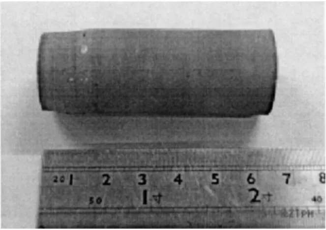
According to Tracey’s study [7], the sintering temperature should lie between 600 and 1000 °C. After being tested, the sintering temperature was set as 630 °C, and the sintering time was 15 minutes. During the sintering process, the furnace was filled with hydrogen to serve as reduction atmosphere. The finished wick structure was shown in Fig. 4.
4. Theoretical Analysis
In order to investigate the correlation between pore radius and maximum heat transfer capacity, the capillary limitation must be introduced in advance. It is the evaporating meniscus in the wick pumping the working fluid in a LHP. For generating enough capillary head to balance the pressure drops in all sections of the working fluid circulation, the meniscus would adjust its curvature in accordance with the heating intensity. When the heating power increases, both the vapor and liquid flow rates are raised. The flow frictions in the tubes hence increase. For balance, the curvature of the meniscus would become larger. Once the heating power increased continuously but the curvature could not become any larger, the dry-out phenomenon would occur since the capillary head could not balance all the pressure drops. At this time, the capillary force reaches a maximum. The balance condition between the capillary head and the sum of pressure drops in all sections of the working fluid circulation could be expressed as follows:
∆Pcap=
2σ rc ≥∆
Pvl+∆Pll+∆Pw+∆Pphase+∆Pgroove+∆Pg+∆Pc (3)
By analyzing the various pressure drops, the maximum heat transfer capacity could also be derived as Q ≤ 2σ rc −ρ gH sin Ψ µl 2πhfgρlKWLW ln Do Di + 8µvLgroove πρvrh4hfg + 128Lvµv πhfgDi4ρv +128(Ll+ Lcond)µl πhfgDi4ρl (4)
The derivation of the equations and the details of the various pressure drops can be found in Cheng’s study [6]. In general, the experimental formula of sintered spherical powder was used to predict the pressure drops due to the wick. However, it may not be suitable to predict the wick pressure drop for the other shape of sintered powder. Hence, in present study, an experiment was conducted
to fabricate a wick structure by dendritic nickel powder, and their parameters were also measured. Furthermore, an experimental formula of sintered dendritic nickel powder would be established.
5. Experimental Equipment and Method
5.1 Measurement of wick parameters
In this study, the wick structures were pressed and sintered at fixed porosities from 65 to 80%. The wick parameters included pore radius and porosity were measured by the mercury porosimeter (Autopore 9520). The permeability was measured according to the ASTM standard [8].
5.2 Testing thermal performance
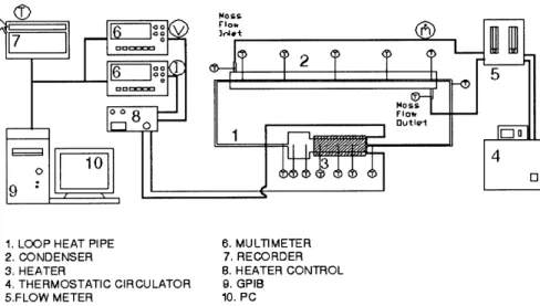
The test system shown in Fig. 5 was used to measure the heat transfer capacity of the LHP. Here, power supply provided the demand heating power, and the sink was simulated by a water cooler whose flow rate was controlled by a flow meter. The temperature on the evaporator and condenser were measured by thermal couples, and a recorder captured the measured data. By measuring the temperature on both the inlet and outlet of the condenser, the heat transfer capacity could be obtained, and the equation was expressed as
Q = m.Cp(Tc,out− Tc,in) (5)
The respective average temperature on the evaporator and condenser would also help to obtain the system thermal resistance, and could be expressed as
R =(Te,avg− Tc,avg)/Qc (6)
Here, the uncertainty of heat transfer capacity and thermal resistance were estimated to be about 4.9% and 5.5%, respectively.
6. Results and Discussion
6.1 Measurement of wick parameters
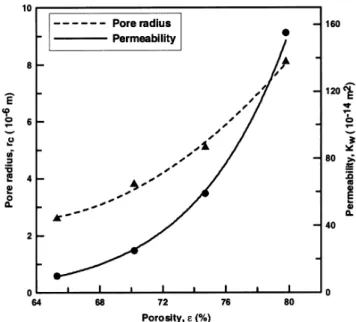
The correlations of wick structure parameters which included pore radius (rc), porosity (ε),
and permeability (Kw) are shown in Fig. 6. As indicated by the line with H symbols, the pore radius reduces with the decreasing porosity. As is known to all, the smaller the pore radius, the higher the capillary pressure head to overcome the sum of pressure drops in all sections of the working fluid circulation. That is, higher capillary pressure would enhance the performance of the LHP. However, the permeability lowers with the decreasing porosity simultaneously. Besides, it would increase the friction of working fluid which flows through the wick structure and hence weaken the performance of the LHP. Consequently, large pore radius would lead to high permeability and hence lower the pressure drop of sintered wick. However, it would reduce the capillary pressure produced by evaporating meniscus simultaneously. Therefore, there exists an optimal combination of wick structure parameters by which the performance of the LHP would achieve optimumly.
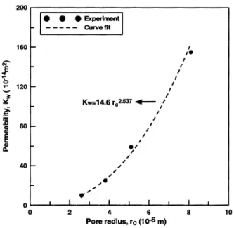
In addition, according to curve fit of the experimental results shown in Fig. 7, an experimental formula of sintered dendritic nickel powder was established for designing and optimizing the wick structure parameters that would affect the heat transfer capacity of the LHP, expressed as
Kw= 14.6rc2.537 (7)
6.2 Heat transfer capacity Q
Figure 8 reveals the correlation between pore radius and maximum heat transfer capacity at the allowable working temperature 80 °C. The maximum heat transfer capacity of the LHP increases
with reducing pore radius. However, once the pore radius is less than 3.8 µm, it would weaken contrarily. This is because reducing the wick pore radius would decrease the permeability of the wick structure and hence weaken the maximum heat transfer capacity of the LHP. In the present study, when the porosity was 70% and pore radius was 3.8 µm, the maximum heat transfer capacity of the LHP was up to 500 W.
Fig. 7. The correlation between pore radius and permeability.
6.3 Thermal resistance
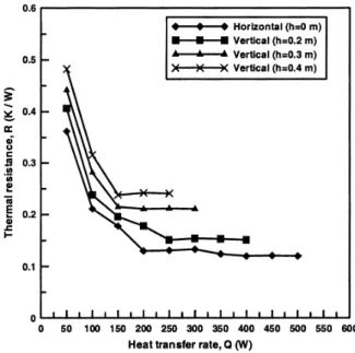
Figure 9 shows the correlation of heat transfer capacity and thermal resistance. The thermal resistance decreases with the increasing heat transfer capacity, but would reach a constant value when heat transfer capacity is more than a certain value. The reason is that the condensed length would vary with different applied heat. For example, the higher the applied heat, the more condensed area for condensing the vapor flow was used and hence the smaller thermal resistance. Figure 9 also reveals that, in horizontal operating mode, when the heat transfer capacity was more than 200 W, the thermal resistance would achieve a constant value of about 0.12 °C/W.
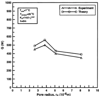
6.4 Comparison between theory and experiment
According to the capillary limitation and the experimental formula of sintered dendritic powder, theoretical prediction about the correlation between heat transfer capacity and pore radius was shown in Fig. 10. The experimental results revealed that the heat transfer capacity increased with the reducing pore radius, and the theoretical results had a similar trend.
In addition, there exists a difference between theoretical prediction and experimental results. The reason is that, in compensation chamber, the subcooling degree of working liquid was used to compensate for the heat leak theoretically. However, due to the influence of environment factor, the subcooling degree would not be always enough to compensate the heat leak experimentally. It would raise the temperature on both compensation chamber and evaporator core, and affect the LHP performance. This may explain the difference between theoretical prediction and experiment results.
The other reason is that when the heat flux increased, the generated vapor would not only flow toward the vapor channel but also penetrate to evaporator core. It would raise the temperature on the evaporator core and hence lower the system performance.
7. Conclusions
In order to establish an experimental formula of sintered dendritic nickel powder, wick structures were pressed and sintered at respective fixed porosities and their parameters including porosity, pore radius, and permeability were also measured. According to both the capillary limitation and the present experimental formula of the sintered dendritic nickel powder, the wick structure parameters that would affect the heat transfer capacity of the LHP were analyzed theoretically and then tested experimentally. The major results are listed below:
1. According to the measured results of wick parameters, an experimental formula for the sintered dendritic nickel powder was established and expressed as below:
Kw = 14.6rc2.537
2. The maximum heat transfer capacity of the LHP can be predicted by the capillary limitation and the present experimental formula. The result shows that there exists an optimal combination of wick structure parameters by which the performance of the LHP would achieve optimization.
3. The fabricated LHP achieved the heat transfer capacity of 500 W at the allowable working temperature 80 °C and the thermal resistance was 0.12 °C/W.
4. The theoretical and experimental results showed the same trend, and the difference between theory and experiment was about 10%.
Acknowledgment
The financial support from the National Science Council of the R.O.C. for project NSC 91-2218-E-002-027 is gratefully acknowledged.
Literature Cited
1. Maidanik YF, Vershinin S, Kholodov V, Dolgirev J. Heat Transfer Apparatus. US Patent, No. 4515209, May 7, 1985.
2. Neison JG, Gregg JB, Joseph MG. Fine pore loop heat pipe wick structure development. SAE Paper No. 961319, 1996.
3. Lai CC. The impact of wick structure parameters on the performance of sintered miniature heat pipe. Master Thesis, National Taiwan University, Taipei, Taiwan, ROC, 2000.
4. Chan JH. Heat transfer enhancement of sintered miniature heat pipe. Master Thesis, National Taiwan University, Taipei, Taiwan, ROC, 2001.
5. Chi SW. Heat pipe theory and practice. McGraw-Hill: New York; 1976.
6. Cheng KC. Loop heat pipe with the fine-pore wick structure. Master Thesis, National Taiwan University, Taipei, Taiwan, ROC, 2002.
7. Tracey VA. Pressing and sintering of nickel powders. Intl J Powder Metallur Powder Technol 1984;20:281–285.
8. ASTM E128-61. Standard test method for maximum pore diameter and permeability of rigid porous filters for laboratory use.
"F F F"
Originally published in Proc 2003 Symp Transport Phenomena and Applications, p 55, Taipei, Taiwan, ROC.
Translated by Yau-Ming Chen, Department of Mechanical Engineering, National Taiwan University, Taipei, Taiwan 106, R.O.C.