High-speed hardware decoder for
double-error-correcting binary BCH codes
Shyue-Win Wei
Che-Ho Wei
Indexing terms: Algorithms, Codes and decoding, Errors and errnr unalysis
Abstract: The paper presents a new hardware decoder for double-error-correcting binary BCH codes of primitive length, based on a modified step-by-step decoding algorithm. This decoding algorithm can be easily implemented with VLSI circuits. As the clock rate of the decoder is inde- pendent of block length and is only twice the data rate, the decoder is suitable for long block codes working at high data rates. The decoder comprises a syndrome calculation circuit, a comparison circuit and a decision circuit, which can be real- ised by linear feedback shift registers, ROMs and logical gates. The decoding algorithm, circuit design and data processing sequence are described in detail. The circuit complexity, decoding speed and data rate of the new decoder are also dis- cussed and compared with other decoding methods.
1 Introduction
The Bose-Chaudhuri-Hocquenghem (BCH) codes are a class of extensively studied random-error-correcting cyclic codes [l-41. A double-error-correcting binary BCH code of primitive length is capable of correcting any combination of two or fewer errors. This code is defined as follows [2] :
block length = n = 2" - I, number of information bits = k = n - 2m m 2
3 (integer)
minimum distance = d,,, = 5
The generator polynomial of this code is specified in terms of its roots from the Galois field GF(2'"). If a is a primitive element in the Galois field GF(2'"), the gener- ator polynomial g ( x ) is the lowest degree polynomial over
GF(2) which has a', E',
.
..
, a4 as its roots. Let M , ( x ) be the minimal polynomial of mi, then g(x) has been shown to beg(x) = M l ( 4 M 3 i X ) (1)
and the degree of g(x) is just 2m. A summary of these BCH codes is given in Table 1 [2]. The popularly
employed error-correcting procedure for double-error- correcting binary BCH codes consists of three major steps [ 1 4 :
(a) Calculate the syndrome values Ski = 1, 2, 3) from the received word.
~~~ ~~
Paper 64641 (E16), first received 3rd May and in revised form 21st October 1988
The authors are with the Institute of Electronics, National Chiao Tung University, 45 Po-A1 Street, Hsin Chu, Taiwan, Republic of China
(b) Determine the error location polynomial u(x) = 1
+
S , x+
(S,+
S3/S,)x2 from the syndrome values. (c) Find the roots of u(x), which are the error locators. Since the calculations in step (a) and step (b) in decoding the double-error-correcting binary BCH codes are quite simple, the work of step (c) becomes an important subjcct for decoding this kind of code. Chien's search algorithm is the most efficient. To determine the roots of u(x), many methods can be used to implement Chien's search algo- rithm [S-SI. The most straightforward is the lookuptable method, although it is unpractical for long block codes [8]. Another hardware circuit which can be used to implement Chien's search algorithm in a straightforward manner is called the Chien searcher [ l , 51. This circuit needs two multipliers to compute u(x = a?. For long block codes, the circuit complexity increases and the cost of fast hradware circuits would be very expensive. Usually, a microprocessor-based software decoder can be used for long block codes [&SI. However, due to the
limited speed of central processing units, if a higher data rate is specified, a microprocessor-based method can only be used for medium block lengths (e.g. m = 7). Another algebraic decoding method, known as the step-by-step decoding method, involves changing the received symbols one at a time and testing to determine whether the weight of the error pattern has been reduced [3, 9-11]. The difference between this algorithm and Chien's search algorithm is that the step-by-step algorithm checks every potential error-location directly instead of searching the error-location numbers. A completely described step-by- step decoding algorithm for general BCH codes has been proposed by Massey [SI, and also by Szwaja [lo]. This general decoding algorithm has not been widely employed for large multiple-error-correcting codes owing to its requirement for calculation of the determinant of the syndrome matrix.
In this paper, a simple double-error-correcting decoder using a modification of the conventional step-by-step decoding method is proposed. It is suitable for high data rates and long block lengths of double-error-correcting
binary BCH codes. Before introducing this modified step- by-step decoding algorithm, some properties of double- error-correcting binary BCH codes are briefly described
in the following Section.
2 Properties of double-error-correcting binary BCH codes
If K ( x ) is the k - 1 degree information polynomial, then the encoded codeword c(x) can be expressed in a system- atic form as
c(x) = K ( x )
+
mod { K ( x ) x " - ' / g ( x ) }= CO
+
clx+
" '+
C , _ I x " - l (2)221 IEE PROCEEDINGS, Vol. 136, P t . I , No. 3, J U N E 19x9
where, mod { K(x)x"-'/g(x)} indicates the remainder polynomial of K(x)x"-' divided by g(x). Hereinafter, all codewords are assumed to be in systematic form. Let the error polynomial be e(x), then the received-word poly- nomial is given by
r(x) = c(x)
+
4x1
= ro
+
rlx+
. . .
+
r,-,x"-l (3) If the syndrome values S1 and S , are expressed in poly- nomial form asthen, by defining a remainder polynomial b(x) = mod {r(x)/MXx)}, the syndrome values can be also obtained from
( 5 )
SXx)l = b(x)l x = d , i = 1, 3
x = n
Therefore, the calculation of syndrome values can easily be implemented by employing two m-stage shift registers with feedback connections [12], which are denoted as rn-stage remainder shift register dividers. To correct all patterns of two or fewer random errors, the following relations between syndrome values can be applied [ 11 : if there is no error, then
s1
=s,
= 0 ( 6 4SI # 0 and S , = ( 6 4
SI # O and S , # ( S J 3 ( 6 4 If there is one error only, then
If there are two errors, then
If there are three errors, the syndrome values could be
S , = 0 and S , #(SI),,
or SI f O and S 3 # ( S $ ( 6 4
This is because the dmin of the codeword is equal to 5 ; the syndrome values could be the same as another codeword with two errors.
The cyclic structure of BCH codes was proved by
Peterson in 1960 [12]. If r")(x) is obtained by cyclically
shifting j bits of I(x) to the right, then it can be expressed as
r")(x) = mod
{-}
=
+
r n - j + l x+
...
+
rn-lxj-l+
r o x J +...
+
rn-j-lxn-l (7) Similarly, the shifted remainder polynomials by'(x) and b$"(x) can be obtained asbr(x) = mod {r"'(x)/Mi(x)}
= mod {x'bXx)/Mdx)}, i = 1, 3 (8)
Hence bp)(x) can be obtained by cyclically shifting bdx) by j bits and dividing by M,(x) (that is, bp)(x) can be obtained by shifting j bits in the remainder shift-register dividers). The corresponding syndrome values are then given by
$(a) = by)(ai), i = 1, 3 (9)
Suppose that it is known that one error occurs at loca- tion x"-j. Let e,(x) = x"-' and r(x) = rl(x)
+
el(x). After 228shifting the polynomial r(x) j bits to the right, the new error pattern becomes ey'(x) = 1, and the shifted remain- der polynomials b?(x) are found to be
bl')(x) = mod {r"'(x)/Mi(x)} = mod {ry)(x)/Mi(x)}
+
1-
(10) b"x) = by'(x)+
1, i = 1, 3 (11) = by)(x)+
1, i = 1, 3For binary BCH codes, eqn. 10 can be rewritten as -
Here, rl(x) implies the received-word polynomial after correcting the x"-j location's error, and the polynomial
m)
is the new remainder polynomial. Consequently, the corresponding new syndrome values are given by- -
$(a) = by'(ai), i = 1, 3 (12)
3 Modified step-by-step decoding algorithm The principle of the conventional step-by-step decoding algorithm can be summarised as three steps [9-lo]. First, it determines the original order of the syndrome matrix (i.e. the number of errors that occur in the received word) by using an iteration method. The syndrome matrix is defined in property 4' of Reference 9. Secondly, it tempo- rarily changes the syndrome values and then corrects the error if the changed syndrome matrix is singular. Finally, it decreases the order of the syndrome matrix by one if an error is found, and shifts one bit to repeat the second step. A new method, based on the properties described above, is presented here. In this method the syndrome values are first changed and then the error in terms of the difference between the initial syndrome values and new syndrome values is corrected. This idea is based on the fact that the number of errors can be determined in terms of the patterns of syndrome values as shown in eqns. 6. This modified algorithm has two advantages:
( U ) it avoids the iteration loop in step 1 of the conven-
tional algorithm
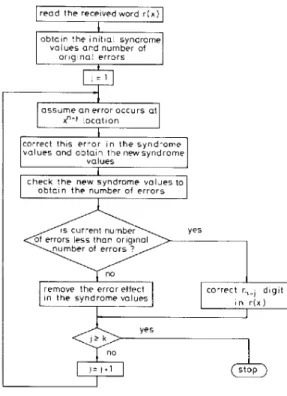
(b) it can be easily implemented by hardware circuits. The flowchart of this modified decoding algorithm is illustrated in Fig. 1.
Using eqn. 5 one obtains the initial syndrome values Sy and S: corresponding to the received word poly- nomial p ( ~ ) before any correction. The number of error bits existing in the received word r(x) can be determined from eqns. 6. If three or more error bits are detected
[SI = 0 and S , # (SJ3], then the next operation is
unnecessary and an alarm or ARQ signal is sent back to end the decoding procedure; otherwise, the next decoding steps are implemented.
The decoder begins to implement its checking algo- rithm after the initial syndrome values have been obtained. First, assume that the x"-l position of the received polynomial r(x) corresponds to an error bit. Then, shifting r(x) one bit to the right will make the error bit occur at position xo. Meanwhile, the contents of the two remainder shift-register dividers are also shifted. To correct the x " - I location error [i.e. xo position of r"'(x)] in the syndrome values, the remainder shift-register dividers are incremented by '1' using eqn. 11. Hence the corresponding error-corrected remainder polynomials
b m and syndrome values
sf,
sf
can be determined. Finally, eqn. 6 is used to check the syndrome values obtained. If the assumption is true, then the first error bit has been found and the number of error bits will decre- I E E PROCEEDINGS, Vol. 136, PI. I, N o . 3, J U N E 1989ment by one. If the assumption is false, then an extra error is added to the remainder polynomial and syn- drome values, so that the number of error bits will
read the receivedword r ( x )
values ond number of original errors
assume o n error occurs at
remove Ihe error effect in the syndrome values
I
x"-l locationcnrrect rn., dlgit i n r ( x )
Fig. 1 Mod$ed step-by-step decoding algorithm
increment by one. Thus, in terms of the change in error bit number one can determine whether x"-' position of r(x) is an error bit or not. When the error bit is detected, the decoder adds correcting bit E, = 1 at the x"-l loca-
tion of r(x); otherwise, an erasure bit
EC
= l is added to the remainder shift-register dividers to erase the effect of the error-bit assumption. After decoding the x"- loca- tion of r(x), the decoder proceeds to decode the x " - ~ position of r(x) by repeating the above procedure. Whenk information bits have been checked and corrected, the received word is decoded completely. Here, the period for decoding one information bit is defined as a 'cycle'.
4 Hardware decoder
The modified step-by-step decoding algorithm can be implemented by a simple structure and with simple hard- ware circuits. Fig. 2 shows the functional block diagram of this decoder. It is partitioned into three parts: syn- drome calculation circuit, comparison circuit and deci- sion circuit. The syndrome calculatjon circuit is used to obtain the new syndrome values S , and
&.
The com- parison circuit is used to determine whether or not S , = 0 and S , = (SI),. The decision circuit is used to checkwhether the error-bit assumption is true or false. After checking, if the error-bit assumption is true, the correct- ing bit E, should be added to- the readout information bit; otherwise, an erasure bit E, is fed back to the syn- drome calculation circuit to erase the effect of the error assumption. The detailed design of these three circuits is described in the following.
IEE PROCEEDINGS, Vol. 136, PL. I, No. 3, J U N E 1989
(a) Syndrome calculation circuit: The remainder poly-
nomials by)(x) and b r ( x ) should add '1' if the error-bit assumption is true; an erasure bit E, is added if the error-
gate
,
recelved-word bufferE, svndrome
4
caIculaiion circuitI
declsion circuit gate 2 a l a r m B o u t gate 3Fig. 2 Functional block diagram of the new decoder
bit assumption is false. Thus, this circuit can be designed by slightly modifying the conventional syndrome calcu- lation circuit [ 2 ] , that is a '1' is added to the inputs of first stages of the remainder shift-register dividers in the decoding procedure and an erasure bit
E,
is added to the outputs of first stages of the remainder shift-register dividers.( b ) Comparison circuit: To determine the number of error bits in eqn. 6, two comparisons must be performed:
(i) Is S , equal to zero? (ii) Is S3 equal to (S,)'?
The results of these two comparisons can be represented by two bits. These two new variables h, and h, are called
'checking bits' :
If Si(.) = 0, then
M,
= 1 ( 1 3 4 If Si(.) = { S { ( C C ) } ~ , then h{ = 1 ( 1 3 4 The corresponding circuit is shown in Fig. 3. Since (Sl)'should be modulo M , ( x ) to a polynomial of degree m - 1 S1,OSl.l S1,rn.l s3,0 s3,1 53,m-I
Fig. 3 Comparison circuit
or less, the cubic operation on S{(a) in eqn. 136 can be implemented by a ROM of size 2" x rn bits using the lookup table method.
( c ) Decision circuit: To check whether or not the infor- mation bit in a current cycle is an error bit, four param- eters hg, h!, h i , h'; are employed. Here h: and h: are the
initial values which represent the original number of error bits in the received word before decoding, while h: and hi represent the number of error bits in the current
decoding cycle. If the number of error bits in the current cycle is less than the initial value (is. the original number of error bits), then the corresponding bit must be an error bit and the decoder sends a correcting bit E , = 1 to the output of the received word buffer. Therefore, the deci- sion circuit can be implemented by a ROM of size Z4 x 2
bits or by a logic circuit as shown in Fig. 4.
1
E,I
alarm Fig. 4 Decision circuit
The proper operation of this decoder can be sum- marised in the following steps:
(1) For .j = 0, gate 1 and gate 3 switch on while gate 2 switches off; the received word vector is read into the buffer with the high-order bits first. If we use the same cycle time to do the shifting operations, then this step needs n cycles. After the nth cycle, initial values (b:, b:),
(S:, Si) and (hy, h!) are obtained. If hy = 1 and h i = 0, then three or more error bits are detected and the decoder returns an alarm or ARQ signal; otherwise, the decodcr proceeds to step 2.
(2) For j = 1, gate 2 switches on and gate 1 switches Off.
(3) Cyclically shift one bit right for the Emainder shift register dividers to get
(h':?(.,,
m,
(q.
Si) and (h{, h i ) .After the decision operation, the corresponding correct- ing bit E , and erasure bit
E,
can be obtained. Now, the error-correcting bit E , obtained will be added to bit r , - jwhen it leaves the receivcd word buffer. The erasure bit
E,
is ready to be added in the remainder shift-register dividers during the next cycle.(4) If all errrors are corrected ( i t hi = 1 and h', = I),
then gate 3 switches off at the beginning of the next cycle.
( 5 ) If j = k , then the procedure is stopped (two LFSRs
are cleared ready for decoding the next received word); otherwise, j is increased by one and the operation pro- ceeds to step 3.
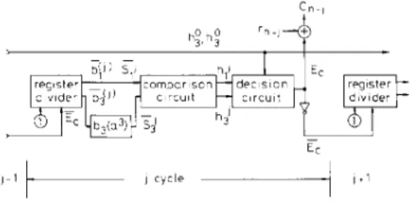
In step 1 of a complete decoding period, the first n - 1 clock cycles are simple shifting operations. In the last cycle of step 1 and in k cycles in step 3, more complicated operations should be completed. Therefore, the decoding time for the last k
+
1 clock cycles will be longer than for the first n - 1 cycles. The data processing sequence in one complete decoding cycle is illustrated in Fig. 5. Also, it should be noted that the operation for 'error-bit assumption' of the ,jth cycle and the erasure of the effect 230of false 'error-bit assumption' of the ( j ~ l)th cycle can be
processed at the same instant. 5
The regular structure of this decoder reduces the hard- ware complexity and makes it easy to design. For a given
Hardware complexity and data rate
C n - , + h;,h; r v E? register divider
61
- Ec j-1'- ) c y c l e-1
Fig. 5 Data processing sequence i n one cycle
desired block length (i.e. given m), the length of the
received word buffer and the stage number of the remain- der shift register dividers can bc determined first. Then the syndrome calculation circuit can be designed using
M , ( x ) and M 3 ( x ) . Next, the 2" x m-bit ROM in the com- parison circuit is implemented using polynomial M , ( x ) . Finally, since the decision circuit is independent of block length, it is fixed for any given m. In general, the new
decoder can easily be implemented for block lengths up to 2" - 1 . The information required to design this decoder is given in Table 1. That this decoder is easier to Table 1 : Double-error-correcting binary BCH codes of primitive length
rn Code rate Minimal polynomials
kln M7.o . . ' M i , m . * W , o " ' M , , m . , 3 0 . 1 4 110 101 4 0.47 1100 1111 5 0.68 10100 10111 6 0.81 1 10000 111010 7 0.89 1001000 11 11000 8 0.94 10111000 111011 10 9 0.96 100010000 1001 10100 10 0.98 1001000000 11 1 1000000 M , ( x ) = 1 + M , , ! x + M , , 2xZ + . ' . + M , , m . , . P - ' +Xm M,(x) = 1 + M 3 , l x + M3,2,? + . . . + M , , , _ , x " - ' + x m
implement than the conventional step-by-step decoder is clearly seen by comparing Fig. 2 and Fig. 1 of Reference 9. Also, this decoder is faster and has lower circuit com- plexity than the hardware decoder of the Chien searcher [l, pp. 132-136; 5, Fig. 21. This is because the Chien searcher requires two multipliers to compute a(x = E'),
and the cost of building wired net to multiply by E' in
GF(2'") in one clock period becomes substantial for larger
m. Usually, it is more economical to allow two shift oper- ations or m clock periods for the multiplication of a'; thus, the decoding speed is degraded.
The new decoder is also faster and easier to implement than one using the microprocessor-based method
[&SI.
Comparing this new decoder with the fast Chien's search method with respect to hardware complexity [8], we find that:
(a) a fast Chien's search algorithm needs a ROM of size 2'" x 1 bit as the segment identifier table, which is 16384 bits for m = 7. The new decoder, however, contains I E E PROCEEDINGS, Vol. 136, Pt. I , No. 3, J U N E fPR9
a ROM of size 2“ x rn bits in the comparison circuit, which is only 896 bits for m = 7
(b) the syndrome calculation circuits for these two algorithms are comparable
(c) the fast Chien’s search algorithm needs a 16-bit processor whereas the new decoder needs only rn
+
6 logic gates.Decoding speed (or data rate) is another important factor, which is usually used to estimate decoder efli- ciency. When the fast Chien’s search algorithm is employed with the microprocessor-based method, the data rate is 383 kbit/s for m = 7 if the clock rate of the processor is 10 MHz. In the new decoder, iff, is the clock rate, then the data rate is (n/n
+
k),f, bit/s, which is 1066 kbit/s for a 2 MHz clock rate and rn = 7. Even when the word length is very long, the decoder can keep the data rate to at least half of the clock ratc. The clock rate and decoding speed depend mainly on the access time of the ROM. At the time of writing most com- mercial ROMs have an access time in the range 150- 250 ns. Specially designed high-speed ROMs with access times under 35 ns and using Rash EEPROM technology are available also (e.g. the XL46HC64 SpeedPROM).6 Conclusions
A new decoder based on a modified step-by-step decod- ing algorithm for double-error-correcting binary BCH codcs has been presented, which requires only n clock cycles for reading the received word and k clock cycles for finding the error bits. Since the checking operation of this modified algorithm only needs to compare the number of current errors with the original errors, the comparison circuit and decision circuit are simplified. Also, the properties of BCH codes described in Section 2 make the error-bit assumption very easy to implement. The working data rate of the decoder depends only on the clock rate, which is determined mainly by the access time of the ROM in the comparison circuit and is inde- pendent of the block length. Therefore, this new decoder may work at a high data rate for high rate codes. Because of its simplicity in structure and circuit realisation, this decoder may easily be implemented using VLSI circuits.
If the data rate is specified, the clock generator can be integrated with the decoder and encoder in one chip.
The decoding algorithm and circuit structure can be extended for complete decoding of double-error-correct- ing binary BCH codes. In Reference 1 (Section 16.48), it is
shown that if Ti-[-] = 1 where
...
-
T r [ x ] =1
x2’ i = othen three or more errors are detected. Thus, the decoder is a complete decoder for double-error-correcting binary
BCH codes if provision is made in the comparison circuit
and decision circuit:
(a) to create a new check bit, say h,, to indicate the value of trace. Here, the calculation of the trace can be straightforwardly implemented by a ROM of size 2’“ x 1
bits
( b ) to refresh the fixed initial values h: in the bounded- distance decoder by hi (for i = 0, 1, 3) when an error bit is
found (i.e. hy = h! if E , = 1).
Similarly, the decoding algorithm and circuit structure can also be extended for other binary BCH codes.
7 Acknowledgment
The work reported in this paper was supported by the National Science Council of the Republic of China as research project NSC 78-0404-E009-09.
8 References
I BERLEKAMP, E.R.: ‘Algebraic coding theory’ (Aegean Park Press, 1984)
2 LIN, S., and LOSTELLO, D.J., Jr.: ‘Error control coding’ (Prentice- Hall, 1983)
3 PETERSON. W.W., and WELDON, E.J., Jr.: ‘Error-correcting codes’ (MIT Press, Cambridge, MA, 1972)
4 MICHELSON, A.M., and LEVESQUE, A.H.: ‘Error-control tech- niques for digital communication’ (John Wiley & Sons, Inc., 1985) 5 CHIEN, R.T.: ‘Cyclic decoding procedures for Bose-Chaudhuri-
Hocquenghem codes’, I E E E Trans., 1964, IT-IO, pp. 357-363 6 BARTEE, T.C., and SCHNEIDER, D.1.: ‘An electronic decoder for
Bose-Chaudhuri-Hocquenghem error-correcting codes’, I R E
Trans., 1962, IT-8, pp. S17-24
7 LE-NGOC, T., and BHARGAVA, V.K.: ‘A microprocessor based decoder for BCH codes’, Can. Electr. Eny. J., 1979,4, pp. 29-32 8 SHAYAN, Y.R., LE-NGOC, T., and BHARGAVA, V.K.: ‘Binary-
decision approach to fast Chien search for software decoding of BCH codes’, I E E Proc. F, Cornmun., Signal & Process., 1987,134, (6), pp. 6 2 9 4 3 2
9 MASSEY, J.L.: ‘Step-by-step decoding of the Bose-Chaudhuri- Hocquenghem codes’, l E E E Trans., 1965, IT-11, pp. 58&585 10 SZWAJA. Z.: ‘On step-by-step decoding of the BCH binary code’,
IEEE Trans., 1967, IT-13, pp. 35&351
I 1 HARTMANN, C.R.P.: ‘A note on the decoding of douhle-error- correcting binary BCH codes of primitive length’, IEEE Trans., 1971, IT-17, pp. 765-766
12 PETERSON, W.W.’ ‘Encoding and error-correction procedures for the Bose-Chaudhuri codes’, IRE 7’rans., 1960, I T 4 , pp. 4 5 9 4 7 0