Chiou-Fan Shie, Shyh-Chour Huang Department of Mechanical Engineering National Kaohsiung University of Applied Sciences
Kaohsiung 807, Taiwan, R.O.C. E-mail: [email protected]
Abstract
The objective of this paper is to design and control of a flexibility microgripper in place of general draw-way movement of cells. In the gripper, the Ground Structure Method of topology optimum is used to define the design domain and obtain topology shape of the flexibility mechanism. The UV-LIGA process is used to fabricate the microgripper with SU-8 thick film. In the actuator, the piezoelectricity ceramics (PZT) microactuator is used to increase the effect of driving and analyze the result with different drive voltages for the output performance. In order to make the gripping control with great precision, we use the fuzzy PID controller system to improve the original PID controller, reduce error of the system, increases the stability, and the hysteresis phenomenon. In the experiment, we combine the actuator with the gripper by designing a platform and replacing the cell with the micro glass bead to carry on the clamp test .
Keywords: Topology optimal, Microgripper, Piezoelectricity Ceramics Microactuator, Fuzzy-PID Controller.
1. Introduction
Recently, the manipulation of small objects of the microscale finds important applications in biological fields. Micromanipulation of microscale particles requires using a microgripper of the size-scale of the manipulated particles. It also requires that such devices allow for controllable actuation of the gripper arms, with range and displacement matching the required size. Micro-Electro-Mechanical System (MEMS) technology satisfies the requirements for the fabrication of such devices.
Early work with microgrippers employed parallel electrostatic plates to drive the gripper, but this required a relatively large voltage, and the objects which could be grasped were limited [1-2]. Many kinds of microgrippers have been used, and various types of materials, fabrication methods, actuators, and grasp forces have been investigated [3-5]. Microgrippers have also been constructed from shape memory alloys (SMA), however, the thermal mechanical constitution relationship of SMA must be overcome [6-7]. Various kinds of microgrippers, such as the adhesion type, and an absorption type were also reported [8-9].
This paper explores the design problems of a microgripper actuated by a piezoelectric microactuator. The problem is formulated as a topology optimization problem and is solved by a compliant mechanism. In topology optimization, we first define the design domain, and then divide it into a large number of finite elements. These elements are then treated as variables defining the truss element, called ground structure parameterization. Next, an optimization theory is used to determine which elements are retained in the design domain.
This microgripper is driven by a piezoelectric microactuator that causes movement in the compliant mechanism. The compliant mechanism gives optimum shape and size when the objective function is minimized. The compliant ©2010 National Kaohsiung University of Applied Sciences, ISSN 1813-3851
mechanism of the microgripper is made by SU-8 thick photoresist.
To achieve high precision-gripping performance, both a reliable actuation mechanism and an effective control method, which considers the dynamics of the microgripper, are required [10-15]. The design, implementation, and validation of the proposed control method for the microgripper are consisted of a Fuzzy-PID controller for position control. The proposed controllers are successfully applied for real-time control of the developed microgripper, and overcome hysteresis of PZT actuator. The controllers also reach good control, reduce system errors to increase steadiness, and obtain the best grasping the results.
2. The Design Procedures
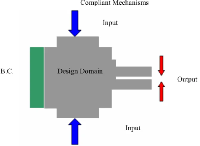
In this paper, a topological-optimization method is developed for the design of the main structure of the compliant mechanism. These designs are capable of transmitting the force and motion of the microactuator to another location in any specified direction. This concept is illustrated conceptually in Figure 1, where a general coupling structure is designed to transfer and deliver the motion of the PZT microactuator to another location. Using topology optimization, an optimal distribution of material is predicted in the specified design domain.
Compliant Mechanisms Input Design Domain B.C. Output Input
Figure 1. Conceptual design of compliant mechanisms 2.1 Topology optimization of compliant mechanisms
The topology optimization theory of compliant mechanisms has developed from topology optimization of the structure. The theory of topology optimization of compliant mechanisms is defined as an unknown design domain. This domain includes domain scales, load location, and boundary conditions.
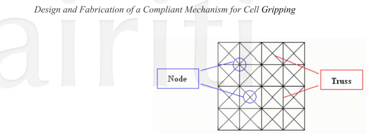
The Ground Structure Parameterization method works as a tool to divide the design domain into n equality truss elements, as shown in Figure 2. As seen, a set of elements, are in a grid of points, where each point is connected to every other point.
2.2 Optimization problem
The topology optimization problems can be divided into two sorts: one is when the structure supports the load, which should apply the stiffness of the structure to optimization, as shown in Figure 3(a). Furthermore, if the structure is concerned with the output displacement at a specific port, as shown in Figure 3(b), the optimization problem should employ flexibility.
Figure 2. Scheme of design domain
Minimum displacement at the points of application of external forces implies that minimum work is performed by the external forces on the structure, thus resulting in a less elastic energy being stored. Therefore, the strain energy (SE) stored in a structure, when it deforms by an applied external force, is often used as a measure of the stiffness of the structure, the smaller the strain energy, the stiffer the structure. SE is used as measure of stiffness of a structure. The strain energy of a general continuum system is expressed, as in equation (1). The optimization can be expressed as a function of SE [16].
1
2
SE
dv
v
σε
= ∫
(1) where the σ is the stress field, ε is the strain field; and v is the volume of the structure system. The integrand in equation (1) is called the strain energy density.For a discretized finite element model of a structure system of SE is given by
{ }
[ ]{ }
1 2
T
SE= U K U (2) where the [K] is the global stiffness matrix and {U} is the global displacement vector.
In the design of a compliant mechanism, we demand one specific port to generate output displacement,
δ
out. The expression for the displacement at the output port,δ
out, in the specified direction under the applied force is given by the mutual strain energy (MSE) [16], defined asout
δ
=MSE d dv vσ ε= ∫ (3)
where
σ
dis the stress field, when only a unit virtual load is applied in the direction of the output displacement at the output port, andε
is the strain field when only the actual load is applied at the input port.For a discretized finite element model, MSE is expressed as:
{ }
T[ ]
{ }
MSE= V K U (4) where [K] is the global stiffness matrix, {V} is the global displacement vector, when a unit of virtual load is applied, as shown in Figure 3(c), and {U} is the global displacement vector, when only the actual load is applied. SE and MSE are used as measures of stiffness and flexibility, respectively.
When the maximum stiffness of the structure to the applied load is desired, the optimization problem is reduced to the problem size to minimize a single object function of SE. When the structure must exhibit maximum stiffness, and generate displacement at a specific port, the optimization problem must be a multi-criteria object function of the
minimum SE and maximum MSE. This study sets the output displacement at one specific port. The objective function that captures the need for (a) compliance to undergo desired deformation, and (b) stiffness to resist external loads once the mechanism assumes the desired configuration. This study combines the criteria of the two desired output posts. Alternatively, MSE and SE can be combined in a ratio-type formulation as :
Minimize: (x )i SE MSE ϕ = (5) Subject to: (x ) x 0 1 g i = − i ≤ ( 6 ) (x ) x 1 0 2 g i = i− ≤ (7) (x) L x A 0 1 n h i i C i = ∑ − = ≤ ( 8 )
where Li is the length variable of the truss element, n is the truss number from the design domain, and Ac is the limit
area of the truss. The SE is the strain energy, while an external force is applied. The MSE is the mutual strain energy, while an unit of virtual force is applied at the output ports. In this context, the thickness of the device is fixed, thus, the only variables are the width and length. The terms xi and Ac are design variables: xi represents the width of every truss element; Ac represents the limitation of the area of the cross section of each truss element.
The optimization result for the truss width is xi (0< xi <1). When the width, i.e. the cross-section dimensions of the element reaches zero, it becomes known which elements should be removed. Therefore, the optimal topology configuration appears once the truss width is known. This optimum structure will transform the motion and force at specific input and output ports, thus, it can be called an optimal mechanism. This optimal mechanism has an optimal design between flexibility and stiffness. In other words, this compliant mechanism can generate larger displacement at specific ports, and has enough stiffness when it supports the load.
in
F
B.C.
Fig. 3 (a) The structure supports load
in
F
out
Δ
B.C.
Unit dummy
load
Fig. 3 (c) Unit dummy load at output port.
B.C.
2.3 Optimization method
The optimization problem model of (5)-(8) has a nonlinear form. This study uses Sequential Linear Programming (SLP) to resolve this problem. The concept of the SLP is to use first-order linear terms in the Taylor’s series expansion to approximate the original nonlinear problem. The problem may be represented as an expression:
minimize:
∑
= Δ ∂ ∂ = n i i i i 1 x x ) x ( ) x ( ϕ ϕ ( 9 ) subject to: 0 x x ) x ( ) x ( ) x ( 1 0 1 1 ∂ Δ ≤ ∂ + = i i i i i i i i g g g ( 1 0 ) 0 x x ) x ( ) x ( ) x ( 2 0 2 2 Δ ≤ ∂ ∂ + = i i i i i i i i g g g ( 1 1 ) 0 1 (x ) (x ) (x ) x 0 x n i i i i i i h h h = ∂ = + Δ ∂∑
≤ (12) The new variable is Δxi, while the nonlinear problem is transformed into a linear problem. To solve this linear problem, give an initial value to xi0, and thus solve the new variable Δxi. Define xi0 as updated by xi0+Δxi, and therefore, substitute the new xi0 into the problem to solve the Δxi again. Repeating the above iteration until the Δxi is smaller than a limited value, thus, the consequent problem is convergence.3. Design of the Microgripper
The design definition of the microgripper is simulated and analyzed in this section. The design domain of topology optimization means “to define the configuration of a mechanism”. The parameters defined by the design domain include, boundary conditions, domain scale, size of finite elements, force applied at input port, number, direction of output ports, and spring constants Ks. The details of the domain definitions are shown in Table 1. In the
process of solving the optimization problem, the ANSYS software package is used to obtain SE and MSE; MATLAB is used to solve optimization.
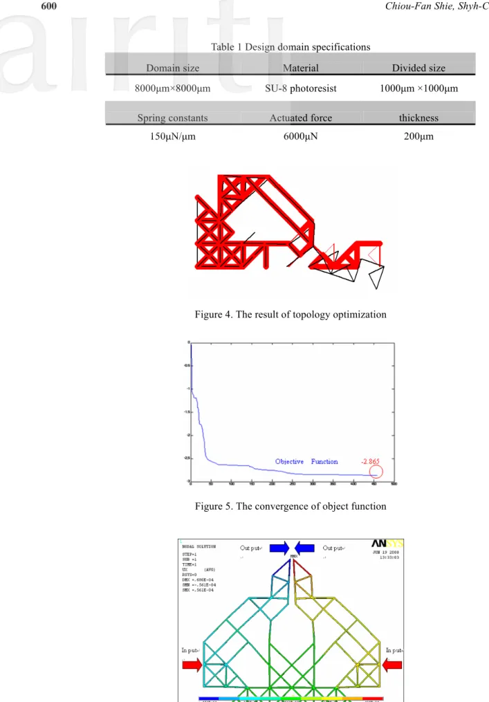
Figure 4 shows the design result of topology optimization for designing a compliant microgripper. The width of every truss element is different, ranging from 0 to 1. The variation in the element sizes, as shown in the figure, actually represent the various truss widths. The object function of optimization is shown in Figure 5. After 495 iterations, the object function slowly converges at -2.865, at an output spring constant at 150N/m, and a thickness of 200μm.
After obtaining the topological-optimization profile, ANSYS software is used to build this resultant model, and simulate it. Figure 6 shows the output displacement of the microgripper, moving in the y-direction at about 56μm at an input displacement of 20μm.
Table 1 Design domain specifications
Domain size Material Divided size
8000μm×8000μm SU-8 photoresist 1000μm ×1000μm
Spring constants Actuated force thickness
150μN/μm 6000μN 200μm
Figure 4. The result of topology optimization
Figure 5. The convergence of object function
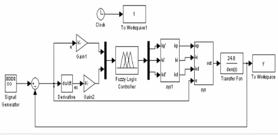
The PID controller is most widely used in industry due to its simple control structure and easy design. The parameters of a PID controller are not easily turned for a nonlinear system with uncertain parameter variations. Fuzzy control is a methodology for representing, and implementing, a human’s heuristic knowledge regarding control of a system. Therefore, Fuzzy and PID controllers can be combined to obtain high performance in a control system. The structure of Fuzzy-PID controller used in this paper is shown in Figure 7.
The controller has the form of PID parameters, which are turned by Fuzzy inference, and provides a nonlinear mapping from the error signal
e t
( )
, and derivation of errorde t
( )
, to the PID parametersK
p,K
i andK
d.Figure 7. Structure of Fuzzy-PID controller
In this paper, the system identification method is used to find the model of PZT microactuator. The commercial software LabVIEW and NI-6014 DAQ card are used for modeling. In the procedure, a strain gauge is used to measure the piezoelectricity ceramics microactuator displacement signal, then a MATLAB ARX (Auto-Regressive eXogeneous) toolbox is used to create the system models, The identification percentage is 93.22%, The transfer function can be expressed as follows:
Transfer Function = 2 24.8 24.5 107.5
S + S+ (13) The fuzzy controller consists of a two-input and three-output controller. The relations between the three PID parameters and e(t) error, ec(t) error rate of change are identified to conform to the different e(t), ec (t) with the control parameters.
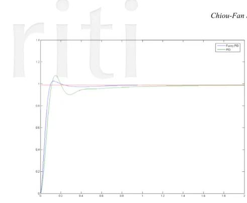
The Matlab model is established by Simulink, there are 49 rules, according to different e(t) and ec (t), to adjust the PID parameters. First, Z-N rule is used to obtain the three PID parameters, Kp = 21.66, Ki = 0.2, Kd = 0.02. The
system response is to step reference input, as compared with conventional PID control (without Fuzzy tuning), as is shown in Figure 8. From Figure 8, it can be observed that the Fuzz-PID controller achieves better tracking response than conventional PID controller, without Fuzzy tuning.
Microgrippers have been successfully fabricated by Photolithography, which is one of the most crucial methods that enable the realization of MEMS devices. The main task of the process is to transfer the mask pattern onto thin films deposited on wafer surfaces. This is done by finishing the common sequence steps in a photolithography room.
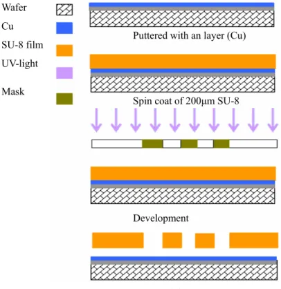
The structural material of a compliant mechanism was modeled by SU-8 photoresistant thick film. In fabricating a compliant mechanism, the intermediary (Cu) is sputtered on the polyimide and coater 500μm thickness SU-8 is spun on it, then lithography is used to obtain the SU-8 structure of the compliant mechanism. As a result, the compliant mechanism can be released by removing the polyimide and intermediary. Figure 9 shows the fabrication process. Figure 10 shows SEM photo of a microgripper.
Wafer Cu
Puttered with an layer (Cu) SU-8 film
UV-light Mask
Spin coat of 200μm SU-8
Development
Removed the structure
Figure 9. The fabrication process of microgripper
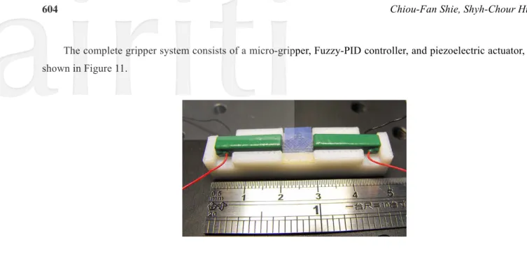
The complete gripper system consists of a micro-gripper, Fuzzy-PID controller, and piezoelectric actuator, as is shown in Figure 11.
Figure 11. Microgripper system
After fabrication, we measure the displacement of the tip. The hysteresis curve drawn from input – output relation is shown in Figure 12. According to the experimental results, the output displacement follows the reference trajectory very accurately. Therefore, the Fuzzy-PID controller proves to be effective for hysteresis compensation and the position of microgripper system.
Figure 12. Experiment of microgripper displacement
Pick-and-place manipulation performed in water has been successfully accomplished with 360μm micro glass beads. The procedures of gripping and moving the micro glass bead is shown in Figure 13.
Positioning Gripping Figure 13. Gripping process
6. Conclusions
In this paper, a new design for a piezoelectric microgripper with a Fuzzy-PID controller is presented. The experimental evaluation shows that a Fuzzy-PID controller could achieve good tracking with respect reference input signals, and therefore, could compensate for the hysteresis phenomenon of microgripper system. The experiment also showed that the gripper fingers, opened to 42μm, and could successfully manipulate micro glass beads of 360μm size in water, which is the similar to the environment where the cell exists.
Acknowledgements
The authors acknowledge and thank the National Science Council for finial support of this work under contract Numbers NSC 97-2221-E-151-001 and NSC 98-2221-E-151-046.
References
[1] Chu, P. B., and Pister, K. S. J., “Analysis of Closed-loop Control of Parallel-Plate Electrostatic Microgripper,” Proceedings of the IEEE International Conference on Robotics and Automation, Vol. 1, 8-13, pp.820-825, May 1994.
[2] Keoschkerjan, R. and Wurmus, H., “A Novel Microgripper with Parallel Movement of Gripper Arms,” 8th International
Conference on New Actuators, pp. 321-324, June 10-12 2002.
[3] Kim, C. J., Pisano, A. P., and Muller, R. S., “Silicon-processed Overhanging Microgripper,” J. Microelectromech. Syst. Vol. 1, pp. 31–36, 1992.
[4] Nguyen, N. T., Ho, S. S and Low, C. L. N, “A polymeric Microgripper with Integrated Thermal Actuator,” J. Micromech. Microeng., pp. 969-974, 2004.
[5] Kim, D. H, Kim, B and Kang, H, “Development of A Piezoelectric Polymer-based Sensorized Microgripper for Microassembly and Micromanipulation,” Microsyst. Technol., pp. 275–280, 2004.
[6] lkuta, K., “Micro/Miniature Shape Memory Alloy Actuator,” Proceedings of the 1990 IEEE International Conference on Robotics and Automation. Vol.3, pp. 2156-2161, 1990.
[7] Kohl, M., Krevet, B., and Just, E., “SMA Microgripper System,” Sensors and Actuators, A 97-98, pp.646-652, 2002. [8] Araiand, F. and Fukuda, T., “Adhesion-type micro end effecter for micromanipulation,” Robotics and Automation, Vol. 2,
1997, pp. 1472-1477.
[9] Tamio, T. and Tatsuo A., “Development of micromanipulation system with two-finger micro hand,” Proc. IEEE Trans. On Robotics and Automation, Vol. 15, 1999.
[10] Sitti, M., Horighuchi, S., and Hashimoto, H., “Tele-touch Feedback of Surface at the Micro/Nano Scale: Modeling and Experiments,” Proc. IEEE/RSJ Int. Conf. Robotics and Systems, vol. 2, pp. 882– 888, 1999.
[11] Zhou, Y. and Nelson, B. J., “The Effect of Material Properties and Gripping Force on Micrograsping,” Proc. IEEE Conf. Robotics and Automation, pp. 1115–1120, 2000.
[12] Park, J., Kim, S., Kim, Deok-Ho, Kim, B., Kwon, Sang Joo, Park, Jong-Oh, and Lee, Kyo-Il, “Identification and Control of a Sensorized Microgripper for Micromanipulation,” IEEE/ASME Transactions on Mechatronics, Vol. 10, No. 5, pp. 601-606, October, 2005.
[13] Goldfarb, M. and Celanovic, N., “A flexure-based Gripper for Small-scale Manipulation,” Robotica Vol. 17, pp. 181–187, 1999.
[14] Eisinberg, A., Menciassi, A., Micera, S., Campolo, D., Carrozza, M. C., Dario, P., “PI Force Control of a Microgripper for Assembling Biomedical Microdevices,” IEEE Proc.-Circuits Devices Syst., Vol. 148, No. 6, pp 348-352, Dec., 2001. [15] Ku, S. and Salcudean, S. E., “Design and Control of a Teleoperated Microgripper for Microsurgery,” International
Conference on Robotics and Automation Minneapolis, Minnesota, pp 889-894, April, 1996.
[16] Saxena, A. and Ananthasuresh, G. K., “On an Optimal Property of Compliant Topologies,” Struct Multidisc Opim. 19, pp.36-49, 2000.