A LOW-COST RASTER ENGINE FOR VIDEO GAME, MULTIMEDIA PC AND INTERACTIVE TV' Chein-Liang Chen, Bor-Sung Liang, and Chein-Wei Jen
Department
of
Electronics Engineering and Institute of Electronics National Chiao Tung UniversityHsinchu, Taiwan, R.O.C.
ABSTRACT
A low-cost Raster Engine (RE) is designed and implemented to improve the performance of 3D computer graphics and image composition application for video games, multimedia PCs and interactive TVs. Three operation modes: Gouraud and Phong shading algorithms, and image composition are incorporated in this chip. Modified digital differential analyzer (DDA), 2-level pipeline, and constant execution time for calculating cos"
8 are proposed as the features of this design. The accelerator is implemented by 0.8um SPDM CMOS VLSI technology and able to release more then 50% CPU loads.
1. INTRODUCTION
The multimedia system plays a more and more important role in nowaday consumer electronics, especially in video games, multimedia PCs, and interactive TVs. It integrates text, graphic, video, image, and audio signals. In order to handle many various signals, the multimedia systems must deal with a huge amount of operations in a short period of time, especially 3D computer graphics in interactive multimedia systems and virtual reality system. To improve the performance of 3D computer graphics, there are many previous works to achieve this goal. However, because the total-hardware-solutions approaches are usually very expensive [l-81, the cost is too high to afford for end- users. Since the rasterization of 3D computer graphics is massive and regular , it is suitable to be accelerated by specific hardware. But the low-cost approaches suffer from the restriction of one specific algorithm only which utilize the dedicated hardware working with a host CPU [9,10]. hence, a low-cost, PC-based graphics subsystem is proposed in this paper, called raster engine (RE) , to offer more operation modes and algorithm which will be suitable for different applications.
The objects in 3D computer graphics are modeled by geometric primitives, like triangles or polygons. After the geometric engine transforms the coordinates of primitives into the device coordinates, each primitive can be
*This work was supported by the National Science Council, Taiwan, R.0.C
under Grant NSC83-0404-E009-041 ~
decomposed into several scan-lines; a scan-line is made of many pixels. Rendering is the process of creating images from object models, while rasterization is the process of calculating pixel values from geometric primitives.
(4
0-
mwrul
crpplns
(b)
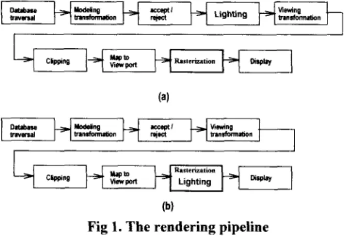
Fig 1. The rendering pipeline
(a) Z-buffered Gouraud shading (b) Zbuffered Phong shading
Gouraud shading and Phong shading algorithms have been developed for rasterization. Fig l(a) and Fig l(b) show the graphics rendering pipelines for Gouraud shading and Phong shading[ 1 11. The blocks before rasterization in the pipeline obtain the primitives by travering database, and perform the coordinate transformation, translation, rotation, and clipping, which are usually done by the geometric engine or CPU. The other blocks of the pipeline deal with rasterization and display. The main difference between two algorithms is when to calculate the pixel intensities by the local reflection model. The much-loved reflection model is Phong reflection model [12]:
I = I , x l & + [ l i x f & J ( L N)+ZjXK,(H* N ) n ] (1) Let
L N = C O S L Y
H . N = c o s ,8
it will change to
I = I, X K,+[Zi X Kd (COS
)+Zi
X K, (COS ,8 (2)Chen, Liang and Jen: A Low-Cost Raster Engine for Video Game, Multimedia PC and Interactive TV 125
where
la : intensity of the ambient light Ii : intensity of the light source
L : the unit vector from pixel to the light source
N
: the normal vector of the pixelH = (L+V)/2,
n : gloss to the model high light
K,, Kd K, : coefficients to model the characteristic where Vis the vector from the pixel to the viewer
of the material
The Phong reflection model imitates the lighting behavior to a degree that produces a first-order approximation to photorealism. We must assume that all light source is point source, all geometry except the surface normal vector is ignored, and ambient is modeled as a constant, because the Phong reflection model is a empirical model
.
It is simplicity and imparts a acceptable realism sufficient for many applications. Although it carries a recognizable computer signature, it is still a good model for low-cost 3D computer graphics solutions.In Fig ](a), the lighting is executed before rasterization, therefore Gouraud shading algorithm applies the local reflection model only at each vertex of the primitives for computing intensities; then, linear interpolation is utilized to produce the intensities in primitives interior on the scan-line basis. However, the scheme can not cope well with highlight. if there is a highlight area inside the primitives, the intensity of pixels will be truncated and replaced by the interpolated value of vertices. So, even Gouraud shading algorithm is very fast and generally used for 3D computer graphics system, that is the main disadvantage.
On the other hand, Phong shading algorithm is known as a normal-vector interpolation algorithm. As shown in Fig I@), the lighting is executed with rasterization and it is for every pixel inside a primitive. The local reflection model is employed after normal vector interpolations, therefore the highlight is well solved. But a huge amount of operations are necessary to deal with the complex calculations of local reflection model on each pixel.
Another important function for multimedia system is image or video signal composition. It is a good way to combine multiple video sources into a single image or to produce the antialiasing result. Porter and Duff [13,14] have proposed RGB
a
model to combine separate elements. We take the operation o f f over b described in their papers as an example:f over b:
rgbc=rgbf+ ( I -
a$
rgbb (3)a
c=a f +
( I -a$ a
b wherergb : means the R,G,B value
a
: means the proportion of the covering areato the whole pixel value c : means combined value f : means front-end value
b : means back-end value
Since the over operation needs only an interpolative operation, it can be integrated into the RE chip.
In order to dominate RE chip, the host CPU provides necessary parameters. The RE runs in its own sequence to perform Z-buffered Phong shading, Z-buffered Gouraud shading or RGB
a
composition according to the selected rendering mode, and then stores its result into frame buffer.2. ALGORITHMS IN RE 2.1 Modified DDA
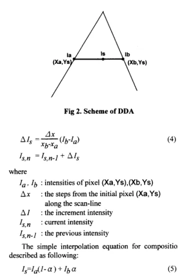
Digital differential analyzer (DDA) [ 121 is nowadays in widespread use for calculating the intensities of pixels on scan-lines in Gouraud shading, as illustrated in Fig 2. It finds how many the values increases along the scan-line, and then repeatedly adding the increment.
Fig 2. Scheme of DDA
(4)
where
l a , Ib : intensities of pixel (Xa,Ys),(Xb,Ys) Ax
A I
Is,n : current intensity I,,n-l : the previous intensity
The simple interpolation equation for composition is : the steps from the initial pixel (Xa,Ys)
: the increment intensity along the scan-line
described as following:
In order to integrate composition mode into RE, we have to modify DDA equation to combine interpolation. After modifying the Eq(4) and Eq(5) , we proposed is
for DDA
= a
for interpolationwhere
I,, Ib : intensities of (Xa,Ys),(Xb,Ys) Ax
the scan-line
Is : current intensity
By assigning different value to
a
I, and select the operation mode, then we can integrate RGBa
composition into RE successfully.2.2 Approximated Phong shading method
: the steps from the initial pixel (Xa,Ys) along
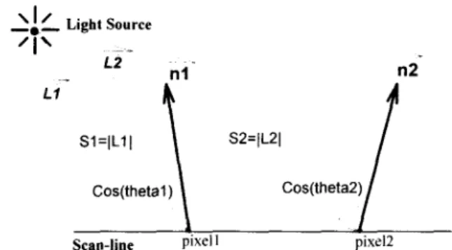
The local reflection model calculation is necessary for each pixel in Phong shading algorithm. Theoretically, square-root operations are needed for each pixel in Phong reflection model to calculate the distance (LI to the light source and distance
Iq
to the viewer from a pixel to normalize the L and V vectors in Eq(1). Fig 3 shows the relationship between the light source and a pixel.If the light source is far enough, the distance from the light source to the pixels in a local area will be almost equal. With this assumption, the pixel 1 in Fig 3 is chosen as the reference pixel, and use the distance S1 to approximate S2. In the sense, instead of calculating each S for each pixel, a single S, said approximated S and it is S1 in this example, is applied to approximate all S in a local area so that a lot of operations are eliminated, and the performance is greatly improved. The introduced error can be easily controlled by updating the approximated S according to an error threshold that is set by users. Therefore, approximated Phong shading is realizable.
Table 1 shows the operations needed to render a 10 X
10 polygon with gloss n=4.
\ I /
'I'~-
-.-
Light Source L2i'
S2=IL21i'
L l Sl=IL11 Cos(theta2)\
I
Cos(theta1) 1 JScan-line pixel' pixel2
Fig 3. Schematic showing the light source and a pixel
According to Table 1, the TotalOps(
+
,-, X , t ) XCost(
+
, - , X , t , J - ) is 14530 for Phong algorithm, and8497 for the approximated Phong method. By applying the approximated Phong method, about 40% total operations have been reduced. Thus, the performance can be greatly improved. The other two rows on the table will be discussed later.
3. HARDWARE DESIGN 3.1 Proposed architecture
There are three major functions to be executed sequentially in the rendering or composition process. They are interpolation for interpolating normal vector, the calculation of cos a and cos" B as shown in Eq(2), and the accumulation of R, G, B pixel values. The Interpolator implements the interpolation function, and the Phong shader implements the cosine functions and the accumulation of R, G, B pixel values, as shown in Fig 4. The block diagram of
1 1
RE is shown in Fig 4. T h e 5 a n d 5 are parameters to normalize the vectors H a n d L , and the other parameters are the same as those in the reflection model.
The detail architecture of Interpolator is shown in Fig 5. There are two kinds of multiplexer MUX and MUX* shown in Fig 5. MUX is a normal multiplexer, while MUX* takes
Shade
I
PhongJ
1 + 1 - 1 x l - : I
Table 1.Operations for rendering a 10 X 10 polygon with gloss n=4:
Chen, Liang and Jen: A Low-Cost Raster Engine for Video Game, Multimedia PC and Interactive TV 727
n j n2 n3 nl n2 q3
Dot Product i Accumulator
Fig 6. SFG of Phong Shader
1's complement of the input value to feed the following adder, so the adder can execute the subtract function directly.
To explore high performance and concurrence, 2-level pipeline and constant execution time for calculating cos" 8
techniques are used in Phong shader. 3.1.1. 2-level pipeline
There are two major functions in the Phong shader, calculation of cosine function (dot-product of two normal vectors) and accumulation of pixel values. The Phong shader is pipelined into two stages according to its functional nature. In addition, there is a 2-substage pipelined multiplier to execute a dot-product or accumulate pixel values so that RE can speed up further.
3.1.2. Constant execution time for calculating cosn 6
To achieve a constant throughput rate, the execution time for calculating cos" 8 must be constant. Table Look-up technique can solve this problem [15]. The disadvantage is the number of tables depends on the gloss n. Another approach [16] is to approximate cos" 8 piecewisely by second order polynomials. This approach suffers from too many operations and conditions to get the approximated value.
Our approach is to use two tables (log2 and 2x, each has 512 words) with a multiplier and a barrel shifter to avoid the dependency on the gloss n. The operations consist of one multiplication, two Table Look-up and one shift. So, constant execution time for calculating cos" 8 is achieved.
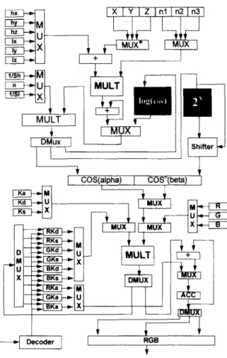
From the above discussion and the signal flow graph (SFG) of the reflection model, as shown in Fig 6, we design the architecture of the Phong shader as shown in Fig 7. In Fig 7, the (X, Y, Z) and (nl, n2, n3) denote the position and normal vector of a pixel. The values of nl, n2, n3, and
Z
are the results of the Interpolator,
X
is implemented by a up- counter to increase the X value step by step, and Y remains as a constant because RE renders a scan-line segment each time. The COS(alpha) and COSn(beta) correspond to cos a and cos" B separately. The values of nl, n2, n3, cos a and cos" B are between 0 and 1. Since RE can not cope with fraction, we scale n l , n2, n3 up to 16 bits, and COS(alpha), COSn(beta) up to 9 bits. Then, during the operation they areshifted right by 16 bits or 9 bits to scale down the values to get the right answers.
3.2. Control circuit
Each functional stage has its own timing sequence, but the execution time for each stage must be the same because RE is a functional pipelining system.
According to the sequential characteristic, the control signals are generated by a counter-based finite state machine(FSM). This control circuit is a three level FSM. The first level is to determine the state of execution, for example, initial-setting state or execution state. The second level is for the sub-states in each functional stage. The third level is embedded in the multiplexer to reduce the control signal lines. For example, a 3-to-1 multiplexer usually needs two signals, SO and S 1, to select the correct input to output. Here, we use only one control signal to trigger the counter inside the multiplexer to select the correct input. Because of
4
+
4
OPI OP2 OP3 OP4
4
3.4 Operation analysis
According to Table 1, the proportions of operations In Phong algorithm:
performed by RE is derived as follows:
(OPT by CPl3 X Cost 6070 (Ops by RE) X Cost = 8460
Ops by R t = 8640
Total Ops 8640+6070 looyo = 58'2 % In approximated Phong method:
(Ops by CPU) X Cost = 922 (Ops by RE) X Cost = 7571
OPs RE
=- X 100% ~ 84.8,s Total Ops 7575+922
Reduced Om by CP [ 6070-922 ,ooo/o 89,,% Ops by CP( in Phong 6070
The above shows that RE can release more than 50% CPU loads, and 89% CPU operations are reduced if the approximated Phong method is applied.
4. LAYOUT AND SIMULATION RESULT 4.1 The Layout View of
RE
SystemThe layout view of this design, Rendering Engine RE, are illustrated in Fig 8 respectively. The gate count of this chip is about 22K. and the die size is about 7684.5um X
7444.81"
4.2 Simulation result
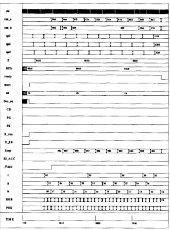
Fig 7. Architecture of Phong Shader The RE is designed and implemented by using ITRVCCL 0.8um SPDM CMOS cell library in the OPUS ~ m h 0 " x - k Since PhoW shading algorithm needs the Interpolator to interpolate normal vector and the Phong shader to calculate the pixel values, it is taken as a simulation example. The Verilog simulation result of Phong shading algorithm is shown in Fig 9. The
(R
G, B)(see Fig 4) of the light source is (25. 200, 116), and (Ka, Kd, Ks) of the polygon is (0.2, 0.1, 0.1). The s~;=0.00116, ;5i=0.00061, and gloss n=4. The H vector is (1 669. 497, 275). and the L vector is (2140, -1110, 2100). The normal vector of the initial pixel is (0.229, 0.688, 0.688), and the incremental vector for the normal vector is (-0.0015, -0.0645, 0.0313). The coordinates of the two end pixels are (1, 1, 50) and (10, 1, 50). The simulation result shows that RE can operate up to 5OMHz so that the pixel update rate is 3M pixels per second for Phong shading, 6M pixels per second for Gouraud shading and composition. Thus, 30K 10 X 10, Z- buffered, Phong shading polygons per second Or 60K 10 X10, Z-buffered, Gouraud shading polygons per second is possible. This ,-hip has been fabricated in TSMC, Taiwan.
5 0 ~ H ~ . the 3-level FSM designs, the number of control signal lines
are reduced almost by half. 3.3. Functions of RE
According to different operation modes, RE can perform composition, Gouraud shading, and Phong shading algorithm. In rendering mode, RE operates on scan-line basis. So, RE renders pixel values for the corresponding scan-line segment after receiving necessary parameters, for example, the coordinates and normal vectors (or intensities) of two ends of the scan-line segment, from the host CPU to RE' In composition mode' the host transfers R' G: B' and
a
values to RE by and the composltlng operation is performed for each pixel.Since each functional stage in RE has its own sequence, 16 system clocks are needed if Phong shading algorithm is selected; 8 system clocks are needed if Gouraud shading or composition mode is sekcted. The expected n-"Nn system clock is 5OMHz. Consequently, the pixel 6M pixels per second for Gouraud shading and composition.
1 1
Chen, Liang and Jen: A Low-Cost Raster Engine for Video Game, Multimedia PC and Interactive TV 129
5. CONCLUSION
In this paper, we have proposed a PC-based low-cost raster engine to enhance the performance of computer graphics and image composition. For Phong shading, an approximated formulation has been derived which can
reduce great computation amount without sacrificing the image quality. Some design techniques have also been revealed and included so that the hardware can be easily pipelined and a high throughput design can be resulted.
This
chip has been designed, verified, and fabricated in TSMC, Taiwan.
REFERENCE
[I] C.B.Harrell and F.Fouladi, "Graphics rendering architecture for high performance desktop workstation," Computer Graphics Proceedings,
Annual Conference Series 93, pp.93-99, 1993.
[2] D.Kirk and D.Voorhies, " The rendering architecture of the
DNIOOOOVS," Computer Graphics, vol. 24, pp. 229 -307, Aug 1990. [3] H.Fuchs, J.Poulton, J.Eyles, T.Greer, J.Goldfeather, D.Ellsworth,
S.Molnar, G.Turk, B.Tebbs, and L.Israel, '' Pixel-planes 5 : A heterogeneous multiprocessor graphics system using processor- enhanced memories," Computer Graphics, vol. 23, pp. 79-88, July 1989.
Computer Graphics, vol. 22, pp. 239-246, Aug. 1988.
[4] K.Akeley and T.Jermoluk, " High-performance polygon rendering, "
[5] K.Akeley, a Superworkstation the silicon graphics 4D/240GTX
superworkstation, " IEEE Computer Graphics and Applications, pp. [6] K.Akeley, '' Reality Engine graphics, " Computer Graphics
Proceedings, Annual Conference Series 93, pp. 109-1 16, 1993. [7] S.Molnar, J. Eyles, J.Poulton, "PixelFlow: High-speed Rendering
Using Image Composition," Computer Graphics, vol. 26, pp. 23 1-240, July 1992.
[8] M.F/Deering and S.R.Nelson, "LEO: A System for Cost Effective 3D Shaded graphics," Computer Graphics Proceedings, Annual Conference Series 93, pp.101-108,1993
Scalable graphics enhancements for PA- RISC workstations," IEEE Compcon, spring 1992.
[IO] K.Harney, M.Keith, C.Lavelle, L.D.Ryan, and D.J.Stark, "The i750 Video Processor: A Total Multimedia Solution ," Communication of
[ 1 I] Foley, van Dam, Feiner, Hughes, Computer Graphics: principles and
[I21 A.Watt, 3 0 Computer Graphics, 2ndEdition, Addison Weley, 1993.
[ 131 T.Duff, "Composition 3-D rendered images," Sigyaph, vol. 19, pp.41- [I41 T.Porter and T.Duff, "Compostiing digital images, " Computer
[I51 G.Knittel, "Verve: Voxel engine for real-time visualization and examination," EUROGfUPHICS'93. vo1.12, no.3, pp.c-37
-
c-48,1993 [I61 J.Jayasinghe, A.Kuijk, and L.Spaanenburg, "A Display Controller foran Object-level Frame Store System," Advances in Computer Graphics
Hardware III ,Springer-Verlag, 1990.
71-83, July 1989.
191 C.Dowdel1 and L.Thayer,
ACM, ~01.34, pp.65-78, April 1991.
practice, 2nd Edition, Addison Weley, 1990
44, Nov. 1985.
graphics, vol. 18, ~ ~ 2 5 3 - 2 5 9 , 1984
1
Fig 9. Result of Phong shading algorithm
Chein-Liang Chen received the B.S. degree in control engineering from National Chiao Tung University, Hsinchu, Taiwan in 1990 and the M.S. degree in electronic eng-ineering from National Chaio Tung Uni-versity in 1994.
His major research interests include 3D computer graph- ics, computer architecture and VLSI architecture for signal processing.
Chein-Wei Jen was born in Shanghai, China, in 1948. He received the B.S. degree from National Chiao Tung University in 1970, the M.S. degree from Stanford Uni- versity in 1977, and the Ph.D. degree from National Chiao Tung University in 1983. He is a professor in the Department of Electronics Engineering and the Institute of Electronics, National Chiao Tung University, Hsinchu, Taiwan. From 1985 to 1986 he was a Visiting Researcher at the University of Southem California, USA. His current research interests include VLSI signal processing, VLSI architecture design, design automation, and fault tolerant computing. He is a member of IEEE and Phi Tau Phi.
Bor-Sung Liang was bom in Kaohsiung, Taiwan, R.O.C. in 1972. He received the B.S. degree in electronics eng- ineering from National Chiao Tung Uni-versity, Hsinchu, Taiwan in 1994.
His major research interests include 3D computer graph- ics, computer architecture and VLSI architecture for signal processing.